Norton Rixson 5700 Series Operator, Push to Pull, and Pull to Push Conversion Installation Instructions_80-9357-0140-020
Open the original PDF document
View PDF5700 Series Power Operator Conversion PUSH to PULL and PULL to PUSH Application

ASSA ABLOY
Patents: 5,881,497; 7,316,096; 7,484,333

/ WARNING
This product can expose you to lead which is known to the state of California to cause cancer and birth defects or other reproductive harm.
For more information go to: www.P65warnings.ca.gov.
Pour la version française voir NortonRixson.com. READ AND FOLLOW ALL INSTRUCTIONS. SAVE THESE INSTRUCTIONS.
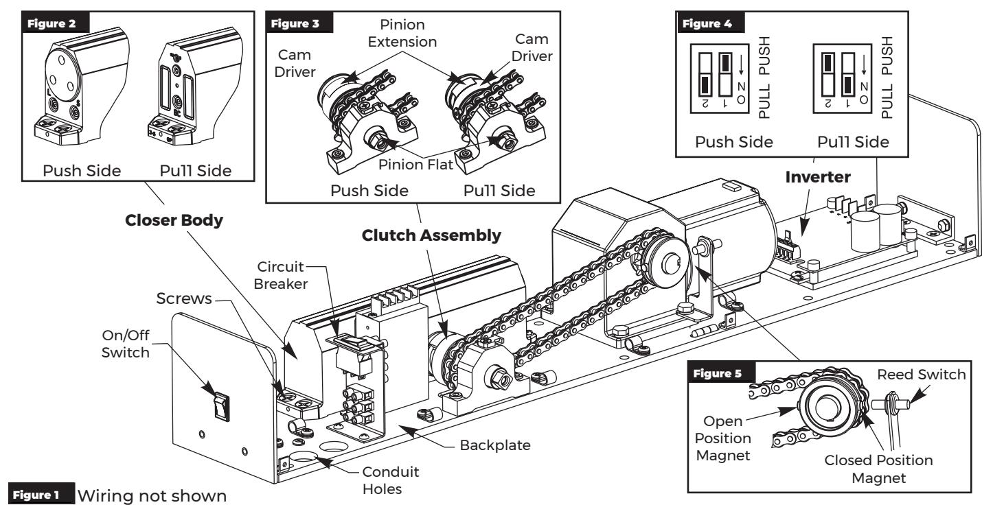
Changing Operator From Push Side Unit to Pull Side Unit
-
1. Verify unit is configured for a push side application:
- Latch and Sweep valves are toward conduit holes. (Figure 2)
- Cam driver of clutch mechanism is toward conduit holes. (Figure 3)
- 2. Turn off power to unit at On/Off switch and flip circuit breaker to OFF position. (Figure 1)
- 3. Using a Phillips head screwdriver, remove four (4) closer body screws and slide closer body away from clutch assembly. (Figure 1)

NOTE: DO NOT remove pinion extension when removing closer body. (Figure 3)
4. Orient closer body with BC valve toward conduit holes and slide onto backplate so that pinion shaft of closer is inserted into pinion extension of clutch assembly. (Figure 2)
NOTE: Some rotational adjustment of pinion extension may be required to allow reassembly of closer pinion shaft and pinion extension. Pinion flat should remain opposite of backplate for proper reassembly. (Figure 3)
- 5. Replace and tighten closer body screws.
- 6. Slide dip switch 1 on inverter from PUSH to PULL position. Slide dip switch 2 from ON to OFF position. (Figure 4)
NOTE: Inverter Details located on page 3.
- 7. Turn on power to unit at On/Off switch and flip circuit breaker to RESET position.
- 8. Immediately after activating unit, watch cam driver as it rotates around. As soon as cam driver contacts pinion extension, flip circuit breaker to OFF position. (Figure 3)
-
9. With door closed:
- Slide closed position magnet so it aligns with reed switch. (Figure 5)
- Slide open position magnet so it is 180° from reed switch. Slide magnet as needed to get proper door opening. (Figure 5)
- 10. Flip circuit breaker to RESET position.

5700 Series Power Operator - Conversion Instructions
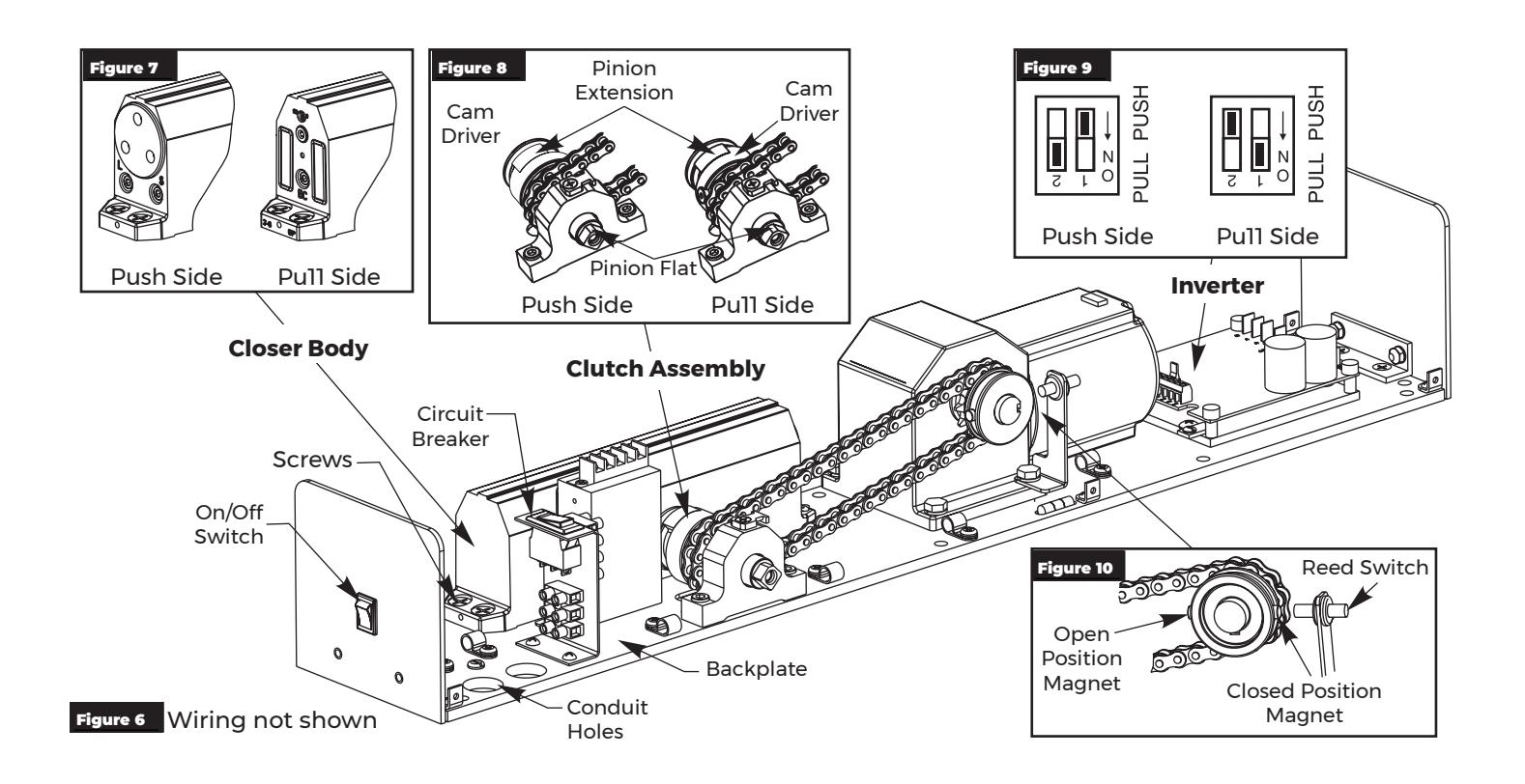
Changing Operator From Pull Side Unit to Push Side Unit
-
1. Verify unit is configured for a pull side application:
- BC valve is toward conduit holes. (Figure 7)
- Cam driver of clutch mechanism is away from conduit holes. (Figure 8)
- 2. Turn off power to unit at On/Off switch and flip circuit breaker to OFF position. (Figure 6)
- 3. Using a Phillips head screwdriver, remove four (4) closer body screws and slide closer body away from clutch assembly. (Figure 6)

NOTE: DO NOT remove pinion extension when removing closer body. (Figure 8)
Orient closer body with latch and sweep valves toward conduit holes and slide onto backplate so that pinion shaft of closer is inserted into pinion extension of clutch assembly. (Figure 7)
NOTE: Some rotational adjustment of pinion extension may be required to allow reassembly of closer pinion shaft and pinion extension. Pinion flat should remain opposite of backplate for proper reassembly. (Figure 8)
- 5. Replace and tighten closer body screws.
- 6. Slide dip switch 1 on inverter from PULL to PUSH position. Slide dip switch 2 from OFF to ON position. (Figure 9)
NOTE: Inverter Details located on page 3.
- 7. Turn on power to unit at On/Off switch and flip circuit breaker to RESET position.
- 8. Immediately after activating unit, watch cam driver as it rotates around. As soon as cam driver contacts pinion extension, flip circuit breaker to OFF position. (Figure 8)
-
9. With door closed:
- Slide closed position magnet so it aligns with reed switch. (Figure 10)
- Slide open position magnet so it is 180° from reed switch. Slide magnet as needed to get proper door opening. (Figure 10)
- 10. Flip circuit breaker to RESET position.
5700 Series Power Operator - Conversion Instructions

Inverter Details
Inverter Adjustments
Based on function adjustment desired, use table to determine witch POT is to be adjusted.
Based on Push or Pull installation, use SW501 dip switch to
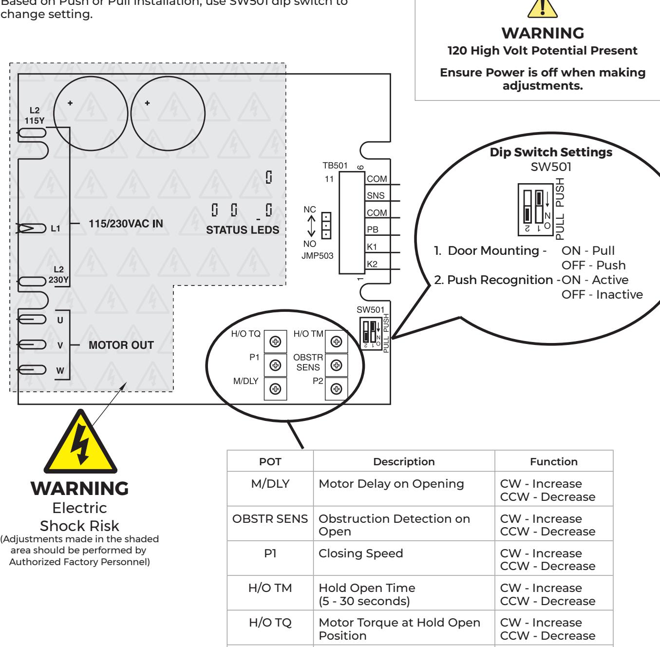
P2 Opening Speed CW - Increase
CCW - Decrease

Technical Product Support: Monroe, NC 28112 USA Phone: 877.974.2255 ext: 2 Techsupport.NortonRixson@assaabloy.com NortonRixson.com