Norton Rixson 5700 Series Operator, 5700P, Push or Pull, Optional Plug-in Power Input Installation Instructions_80-9357-0009-020
Open the original PDF document
View PDF5700P Series Power Operator with Original Plug-in Power Input PUSH and PULL Side Installation Instructions

ASSA ABLOY
WARNING
This product can expose you to lead which is known to the state of California to cause cancer and birth defects or other reproductive harm. For more information go to: www.P65warnings.ca.gov.
Pour la version française voir NortonRixson.com. READ AND FOLLOW ALL INSTRUCTIONS. SAVE THESE INSTRUCTIONS.
The table below provides a list of documents associated with this product. These documents are available for download from www.nortonrixson.com. If additional information or assistance is needed, contact Technical Product Support.
| Document Title | Document Number |
|---|---|
| 5700 Series Push to Pull Application Conversion Instruction Document | 80-8357-0140-020 |
| 5700P Series Push and Pull Template | 80-7357-0002-020 |

Contents
| Components . | 3 |
|---|---|
| General Information | 3 |
| Technical Data | 3 |
| Before You Begin . | 4 |
| Mounting Hardware4 | |
| PULL (Hinge) Side Installation . | 5 |
| PUSH (Stop) Side Installation . | 8 |
| Adjustments . | 11 |
| Input Power Configurations 12 | |
| Final Electrical and Mechanical Setup 13 | |
| Inverter Details | 14 |
| Attach Cover to finalize installation . | 14 |
| Troubleshooting Guide | 18 |
| PULL Template 19 | |
| PUSH Template | 20 |
ADA / ANSI / UL
- 1. Americans With Disabilities Act (A.D.A.) These door operators can be installed and adjusted to conform with A.D.A. regulations.
- 2. ANSI Standards
ANSI A117.1 – These door operators permit door assemblies to conform to the requirements of this specification "for buildings and facilities – providing accessibility and usability for physically handicapped people".
ANSI A156.19 – These products are designed to conform to this specification "for power assist and low energy power operated doors".
- ‒ "PAS" Function is designed to meet or exceed all of the requirements for the "Power Assist Door".
- ‒ "POR" Function is designed to meet or exceed all of the requirements for the "Low Energy Power Operated Door".
3. U.L. Listing
Underwriters Laboratories, Inc. listed for use on fire and smoke barrier door assemblies when the 120VAC (60Hz) power input is supplied through the normally closed alarm contacts of a compatible UL Listed alarm system or alarm panel.
Product Safety Warnings
WARNING: To reduce risk of injury to person, use this operator only with Pedestrian Swing doors. FOR INDOOR USE ONLY
- 1. READ AND FOLLOW ALL INSTRUCTIONS.
- 2. If local code requires unit to be hard wired instead of using plug-in type power cord supplied, this unit MUST be returned to manufacturer and replaced with a unit designed to be hard wired.
- 3. Install only on a properly operating and balanced door. A door that is operating improperly could cause severe injury. Have qualified service personnel make repairs to any hardware before installing the operator.
- 4. Remove, or make inoperative, all locks (unless mechanically and/or electrically interlocked to the power unit) that are connected to the door before installing the operator.
- 5. Do not connect the door operator to the source power until instructed to do so.
- 6. To reduce risk of shock, this operator has a ground plug. This plug requires a grounded receptacle.
- 7. Test door's features at least once a month. After adjusting either force or limit of travel, retest door operator's features. KEEP DOOR PROPERLY OPERATING. An improperly operating door could cause severe injury or death.
- 8. Maximum door size: 48" (1219mm) wide x 250 lb (113.4kg)
- 9. SAVE THESE INSTRUCTIONS.

Components
General Information
- y UL labeled fire or smoke barrier door assemblies require that the 120VAC (60Hz) power input to the 5700P door operator be supplied through normally closed alarm contacts of the alarm system / alarm panel.
- y 120VAC power input to 5700P door operator to be through a NEMA 5-15 outlet located within 15 inches of Power Input end of operator.
- y All wiring must conform to standard wiring practice in accordance with national and local wiring codes.
- y Unit is Non-Handed.
- y Door must swing freely through the entire opening and closing cycle before beginning the installation.
- y Use of an auxiliary door stop (by others) is always recommended.
- y An incorrectly installed or improperly adjusted door operator can cause property damage or personal injury. These instructions should be followed to avoid the possibility of misapplication or misadjustment.
Technical Data
| Input power: | 120VAC, 60Hz | NOTES: |
|---|---|---|
| Power consumption: | .6 amps | |
| Circuit breaker: | 3 amps | |
| Power supply: | 24 V DC, max. 1.1 amp. | |
| Door width: | 28" - 48" Max. (71-122 cm) | |
| Door weight: | 100-250 lb Max. (43-113 kg) | |
| Door opening angle: |
up to 110° PULL side; up to 170° PUSH side;
Manually to 180° PUSH/PULL side |
|
| Hold open time: | 5-30 seconds (A.D.A. 5 seconds min.) |
- y Conduit hole is for low voltage Class 2 wiring ONLY.
- y Input power is NOT to be hard wired into unit.
- y Power cord is to be routed so that it is NOT in any part of a doorway, window opening, wall, ceiling or floor not attached or otherwise secured to the building structure, and not concealed behind walls.
- y Activation devices: push plates, access control, mats, touchless wall switches, etc.
- y Maximum wire size is:
- ‒ 14AWG at terminals 1 4 on Accessory Terminal
- y Rate of operation shall not exceed 300 cycles of opening and closing per hour.

WARNING: Make sure (120V, 60Hz) input power is turned OFF at facility's main circuit breaker before proceeding with installation

Before You Begin
- y All dimensions are given in inches (millimeters). DO NOT scale drawings.
- y Thickness recommended for reinforcements in hollow metal doors and frames is charted.
- y Template information is based on use of 5" (127mm) maximum width butt hinges or 3/4" (19mm) offset pivots.
- y Maximum frame reveal is 1/8" (3mm) for PULL units and 2-5/8" - 6-3/4" (67-171mm) for PUSH units.
- y Before beginning the installation, verify that the door frame is properly reinforced and is well anchored in the wall. Frame header must be straight - without warp or bow.
- y Unreinforced hollow metal frames and aluminum frames should be prepared and fitted with 1/4-20 blind rivet nuts, furnished by others.
- y Concealed switch or sensor wires should be pulled to the frame before proceeding.
Fasteners for Frame:
- y Hollow metal and aluminum: 1/4-20 Machine screws
- y Wood: No. 14 x 2-3/4" (70mm) sheet metal screws
Fasteners for Door:
y 1/4-20 Machine screws 3/8 x 1-5/8" sex nut
| Hollow Metal Door Frame Reinforcing | ||||
|---|---|---|---|---|
| Reinforcing | ||||
| Frame Material | Recommended | Min. Required | ||
| 12 Ga. | 12 Ga. | 18 Ga. | ||
| .105 | .105 | .048 | ||
| (2.66) | (2.66) | (1.21) | ||
| 14 Ga. | 10 Ga. | 12 Ga. | ||
| .075 | .134 | .105 | ||
| (1.90) | (3.41) | (2.66) | ||
| 16 Ga. | 10 Ga. | 12 Ga. | ||
| .060 | .134 | .105 | ||
| (1.52) | (3.41) | (2.66) | ||
| 18 Ga. | 8 Ga. | 10 Ga. | ||
| .048 | .164 | .134 | ||
| (1.21) | (4.18) | (3.41) | ||
Mounting Hardware
| Mounting Hardware | Door or Frame | Drill | |
|---|---|---|---|
|
Unit:
14 x 2-3/4" Sheet Metal Screw |
Wood | 3/16" (4.76mm) | |
|
Unit:
1/4-20 x 1" Flat Head Machine Screw |
Drill #7 (.201 dia. or 5.10mm)
Tap 1/4-20 |
||
|
Track or Arm:
Sex Nut and Bolt (SNB) |
Hollow Metal |
9/32" (7.00mm) thru
3/8" (9.50mm) door face opposite to closer |
|
| (optional) | Aluminum or Wood | 3/8" (9.50mm) thru | |
80-9357-0009-020 Rev 8 11/23

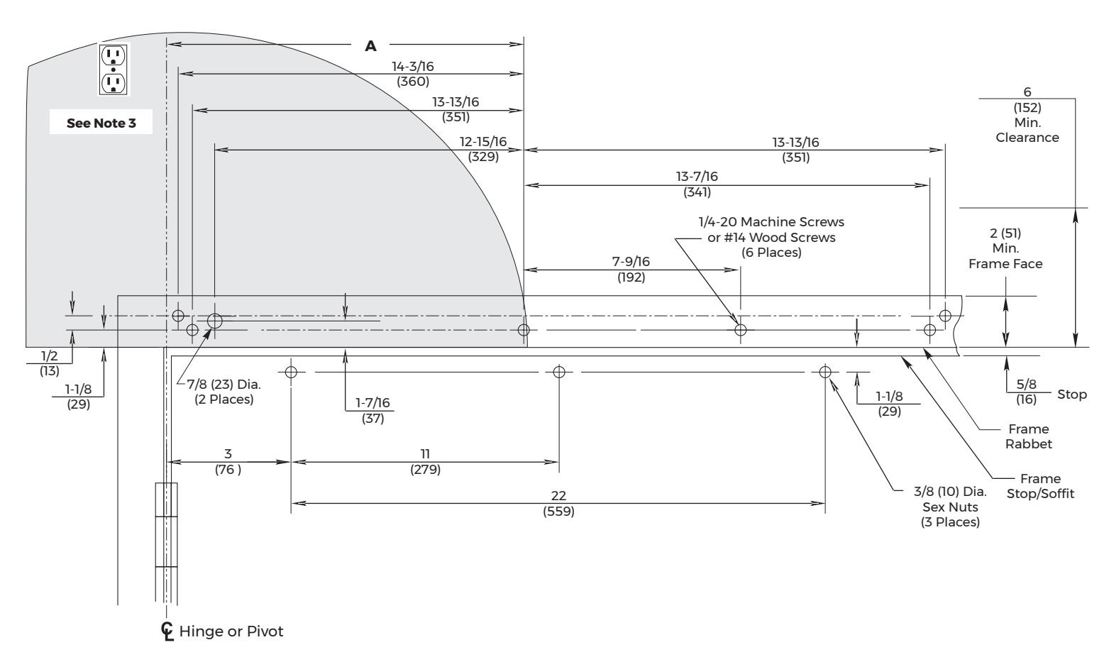
PULL (Hinge) Side Installation
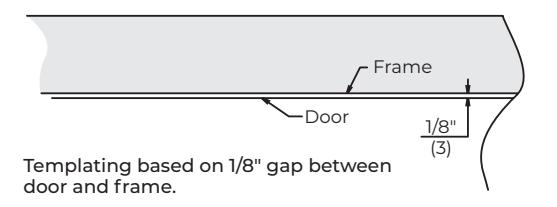
Become familiar with operator components and fasteners. It is recommended that components remain in box until installed. Verify there is minimum ceiling clearance for operator installation before proceeding. (Figure 1)
Prepare Frame and Door
A. Prepare frame for operator.
- 1. Verify frame reveal is maximum 1/8" (3mm). (Figure 1)
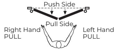
- 2. Determine if push or pull and if left hand or right hand installation. (Figure 2)

NOTE: These steps are for PULL side only. See page 8 for PUSH side installation.
3. Frame header MUST be flat / without twists. Backplate of operator can be used as reference.
NOTE: If frame is not flat or is twisted, an additional steel back plate or shimming is required. Failure to mount unit properly can result in improper function of operator.
- 4. Using detailed template on page 19, prepare six (6) holes for 1/4-20 machine screws or 14 x 2-3/4" wood screws. Blind rivet nut (by others) is suggested for unreinforced hollow metal or aluminum frames. (Figure 3)
- 5. For concealed Class 2 low voltage only: Prepare one (1) 7/8" (22mm) diameter hole for conduit, for switch/sensor wires only.
NOTES:
- · On new construction, this hole will generally be drilled by frame supplier at their shop or at time-of-install.
- Placement of receptacle (outlet) = max 15" (381mm) of power input end of operator (shaded area). (Figure 3)
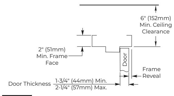
Figure 1
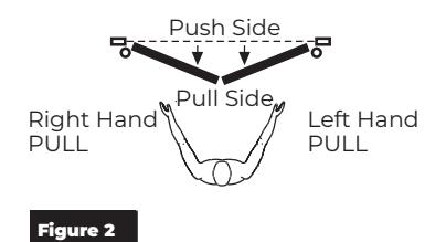
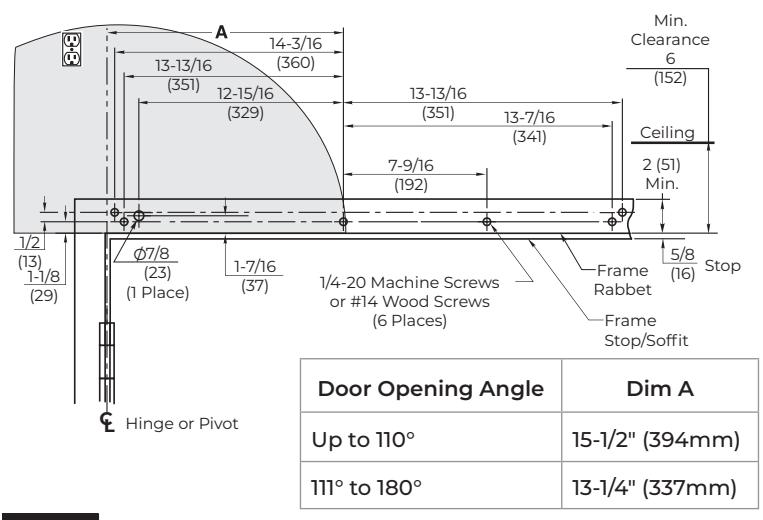
Figure 3 Right Hand Shown
B. Prepare door for track.
1. Using template on page 19, locate and prepare holes in door for three (3) 3/8" (9.5mm) sex bolts (Figure 4)
NOTE: Standard units are supplied with sex nuts and bolts for 1-3/4" (44mm) thick door. Sex nuts and bolts for other door thicknesses are available to order.
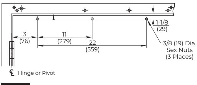
Figure 4 Right Hand Shown
PULL (Hinge) Side Installation (cont.)
Install Operator
A. Remove cover from unit and set cover and screws aside.

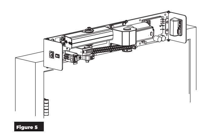
B. Mount unit to frame. (Figure 5)
NOTE: Conduit hole nearest hinge is suggested for 120VAC power input.
Select Concealed or Surface option.

- y Connect conduit to frame side of backplate.
- y Secure unit to frame with six (6) screws.
Surface Class 2 Low Voltage Only :
- y Secure unit to frame with six (6) screws.
- y Mount conduit bracket (found in screw pack) to unit backplate with two (2) provided screws.
- y Connect wiring conduit to bracket.
OR
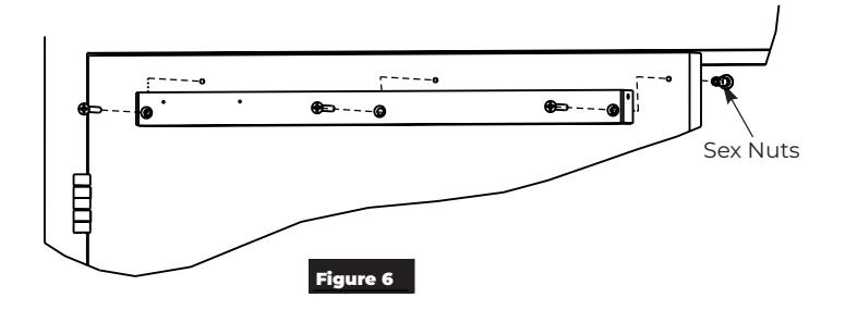
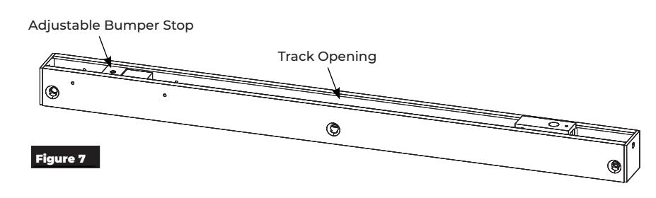
Install Track and Arm
A. Mount track to door.
1. Using previously prepared holes in door, install three (3) 1/4-20 x 1-5/8" screws through track and into sex bolts. (Figure 6)

- y Opening of track is toward top of door.
- y Adjustable bumper stop is toward hinge edge of door.

PULL (Hinge) Side Installation (cont.)
Install Track and Arm (con.t)
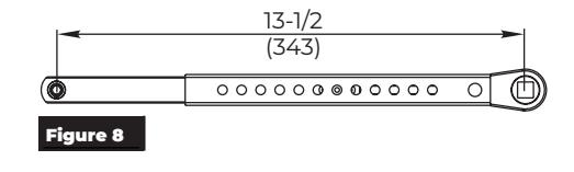
B. Assemble arms.
- 1. Insert slide arm rod into slide arm tube. Distance between pinion square and slide stud is 13-1/2" (343mm). (Figure 8)
- 2. Install 9/64" socket head screw included in screw pack.
NOTE: Center threaded hole of slide arm should align with seventh hole of slide tube. Stud in slide arm should point to same side as holes in slide tube.
C. Install arm assembly to operator.
- 1. Open door.
- 2. Using an adjustable wrench, rotate top pinion 45 degrees toward door hinge. You will feel resistance from spring. (Figure 9)
- 3. While holding pinion at 45 degrees, slide arm on bottom pinion.

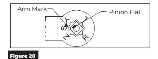
NOTE: Pinion flat should be aligned as shown. (Figure 10)
- 4. Secure main arm to pinion with 1/4-20 x 1/2" screw.
- 5. Insert stud on arm into slider in track then press clip on backside of slider onto stud. (Figure 11)
-
6. To adjust track stop:
- y Use allen wrench to loosen set screw in bumper stop.
- y Open door to full open position.
- y Slide bumper stop until it just touches end of slider.
- y Tighten set screw in bumper stop so bumper will stay in position. (Figure 12)
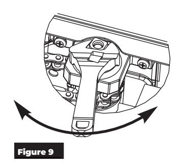
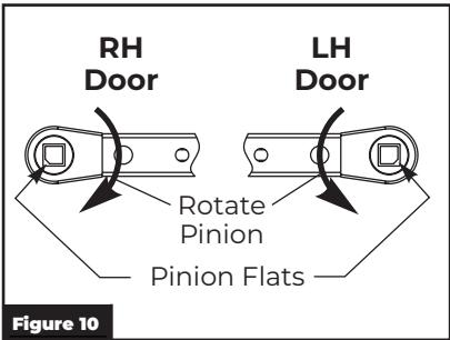
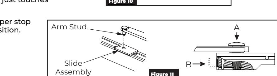
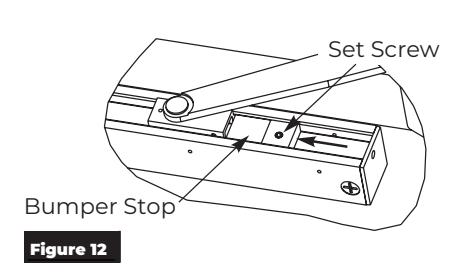
Figure 11

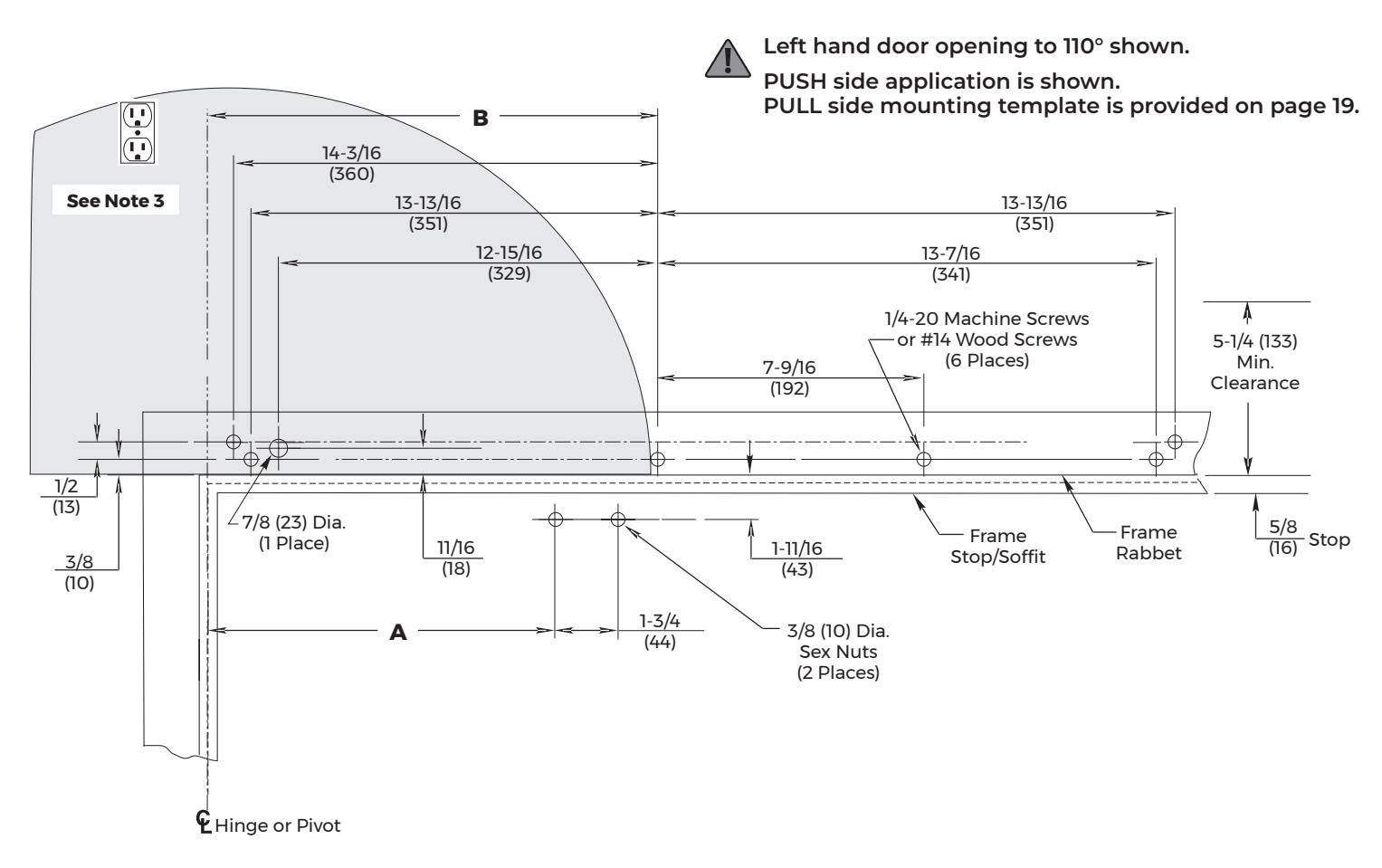
PUSH (Stop) Side Installation
Become familiar with operator components and fasteners. It is recommended that components remain in box until installed. Verify there is minimum ceiling clearance for operator installation before proceeding. (Figure 13)
Prepare Frame and Door for PUSH Side Installation
A. Prepare frame.
1. Verify frame reveal width is 2-5/8" - 6-3/4" (67-171mm). (Figure 13)
NOTE: If frame reveal is less than 3" (76mm), arm adjusting rod can be field cut to 9-1/2" (241mm) measured from centerline of connecting link bushing assembly.
2. Determine if push or pull and if left hand or right hand installation. (Figure 14)

NOTE: These steps are for PUSH side only. See page 5 for PULL side installation.
3. Frame header MUST be flat / without twists. Backplate of operator can be used as reference.
NOTE: If frame is not flat or is twisted, an additional steel back plate or shimming is required. Failure to mount unit properly can result in improper function of operator or inability to snap on cover.
- 4. Using template on page 20, prepare six (6) holes for 1/4-20 machine screws or 14 x 2-3/4" wood screws. Blind rivet nut (by others) is suggested for unreinforced hollow metal or aluminum frames. (Figure 15)
- 5. For concealed Class 2 Low Voltage: Prepare one (1) 7/8" (22mm) diameter hole for conduit, for switch/sensor wires.
NOTES:
- y On new construction, this hole will generally be drilled by frame supplier at their shop or at time-of-install.
- y Placement of receptacle (outlet) = max 15" (381mm) of power input end of operator (shaded area). (Figure 15)
Figure 13

PUSH (Stop) Side Installation (cont.)
Prepare Frame and Door for PUSH Side Installation (cont.)
B. Prepare door for arm assembly.
1. Using template on page 20, locate and prepare two (2) 3/8" (9.5mm) holes in door for sex bolts. (Figure 16)
NOTE: Standard units are supplied with sex nuts and bolts for 1-3/4" (44mm) thick door. Sex nuts and bolts for other door thicknesses are available to order.
|
Door Opening
Angle |
Dim A |
|---|---|
| Up to 110° | 12" (305mm) |
| 111° to 170° | 9-1/2" (241mm) |
Figure 16 Left Hand Shown
Install Operator
A. Remove cover from unit and set cover and screws aside.
B. Mount unit to frame. (Figure 17)
NOTE: Select Concealed or Surface option.
Concealed Class 2 Low Voltage Only:
- Connect conduit to frame side of backplate.
- Secure unit to frame with six (6) screws. Surface Class 2 Low Voltage Only:
- Secure unit to frame with six (6) screws.
- Mount conduit bracket (found in screw pack) to unit backplate with two (2) provided screws.
- · Connect wiring conduit to bracket.
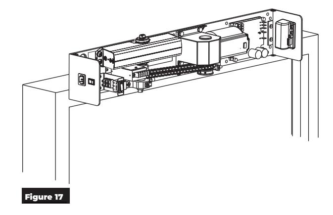

OR

PUSH (Stop) Side Installation (cont.)
Install Arm
A. Mount forearm shoe to door.
1. Using previously prepared holes in door, install two (2) 1/4-20 x 1-5/8" screws through shoe and into sex bolts. (Figure 18)
NOTE: Orient shoe with short side of shoe toward hinge.
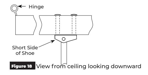
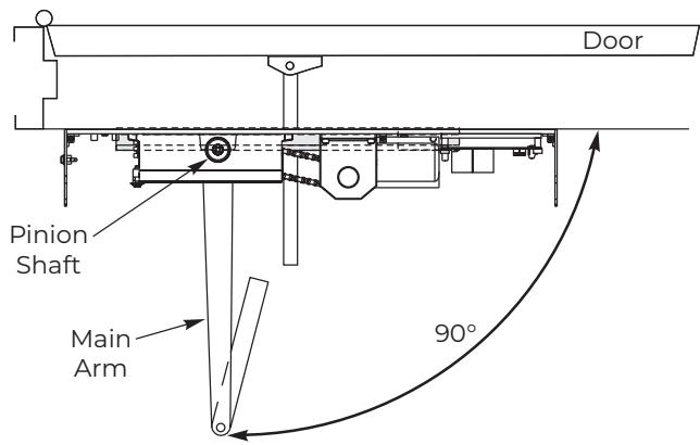
Figure 19 View from ceiling looking downward
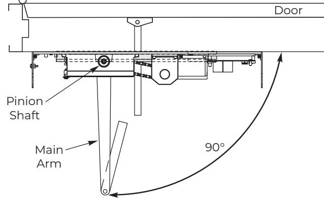
B. Install main arm to operator.
1. Insert main arm onto pinion shaft of unit at 90° angle to frame. (Figure 19)

NOTE: Align arm mark "S" with flat corner of pinion shaft square. (Figure 20)
2. Secure main arm to pinion with 1/4-20 x 1/2" flange head screw.
C. Preload arm.
- 1. Open door.
- 2. Remove 1/4-20 hex head screw on forearm adjusting rod. (Figure 21)
- 3. Insert adjusting rod into adjusting tube. (Figure 21)
- 4. Reinstall 1/4-20 screw and leave loose.
- 5. Rotate main arm in direction away from hinge edge until adjusting rod and tube are perpendicular (at 90° angle) to frame.
- 6. Tighten 1/4-20 hex head screw on adjusting rod to secure arm in this new position.
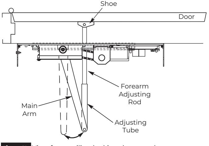
Figure 21 View from ceiling looking downward


Adjustments
A. Adjust mechanical closer features.
NOTES:
- Make necessary mechanical adjustments so unit functions as a standard surface mounted door closer before adjusting spring force, applying power, adding accessories or making electrical/ programming adjustments.
- Refer to table for recommended minimum opening/closing times per ANSI/BHMA A156.19. (Figure 24)
- · Use hex wrench to make adjustments.

Do not remove valves from closer. Hydraulic oil will escape.
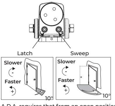
- 1. Closing Speed Controls (Figure 22)
- 2. Valve "S" controls Sweep Range from full open to 10°.
- 3. Valve "L" controls Latch Range from 10° to closed.
-
4. Opening Cycle (Figure 23)
- Valve "BC" controls strength of cushioning in Backcheck Range.

NOTE: Too much backcheck can affect operation of unit pump, preventing full open of door. This valve may require fine tuning after all other adjustments have been made.
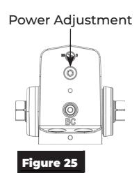
B. Adjust spring force.
NOTES:
- The amount of effort to manually open or close a door is called force and is controlled by the operator's closer spring.
- Make necessary mechanical adjustments described in "A" above.
- A closer set to ADA required 5 lbs opening force may not be strong enough to close door due to latching hardware, air pressure, or frame issues.
- Using 1/8" hex wrench, turn power adjustment screw clockwise to increase door closing power. (Figure 25)
NOTE: Door control is shipped set at midpoint of power setting. Maximum closing power can be achieved with 8 (360°) clockwise turns of power adjustment screw.
A.D.A. requires that from an open position of 70°, door will take at least 3 seconds to move to a point 3" (75mm) from latched position, measured at leading edge of door.
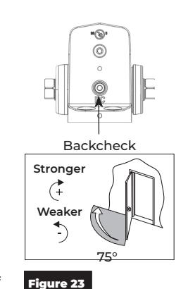
Figure 22
| ANSI/BHMA A156.19 Minimum Opening/Closing Times | |||||
|---|---|---|---|---|---|
| Door Leaf | Door Weight - Pounds (kg) | ||||
|
Width
- Inches (mm) |
100
(45.4) |
125 (56.7) |
150
(68.0) |
175 (79.4) |
200
(90.7) |
| 30" (762) | 3.0 sec | 3.0 sec | 3.0 sec | 3.0 sec | 3.5 sec |
| 36" (914) | 3.0 sec | 3.5 sec | 3.5 sec | 4.0 sec | 4.0 sec |
| 42" (1067) | 3.5 sec | 4.0 sec | 4.0 sec | 4.5 sec | 4.5 sec |
| 48" (1219) | 4.0 sec | 4.5 sec | 4.5 sec | 5.0 sec | 5.5 sec |
Backcheck : Adjust backcheck to have minimum opening time to backcheck or 80 degrees (whichever comes first) based on Table.
Closing Time : Adjust latch and sweep to have minimum closing time from 90 degrees to latch check or 10 degrees (whichever comes first) based on Table.
Figure 24
11
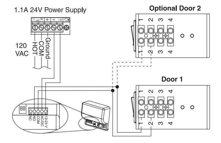
Input Power Configurations
1. Thread conduit fitting into backplate. Concealed Wiring (Figure 26) Surface Wiring (Figure 27)
NOTES:
- y This conduit fitting is for low voltage control wiring only.
- y Check local codes.
- 2. Pull conduit out of header and attach to conduit fitting before mounting unit.
- 3. After installing operator, attach low voltage wiring as illustrated. (Figure 27)
NOTE: Ground wire must be secured to backplate under head of (green) ground screw.
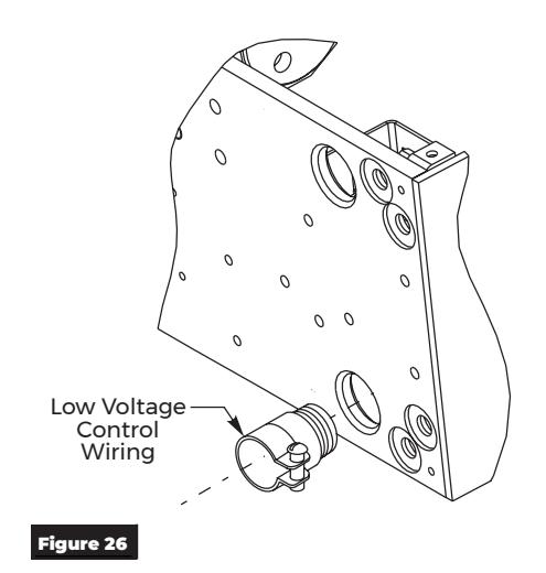
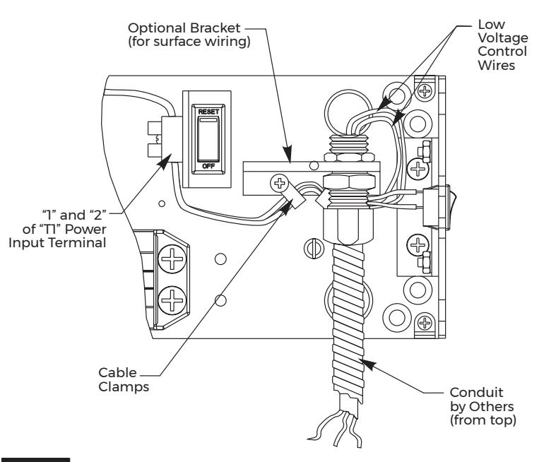
Figure 27

WARNING : HOT and COM of T1 Terminal Block are factory use for incoming power ONLY. These are not to be handled in the field.
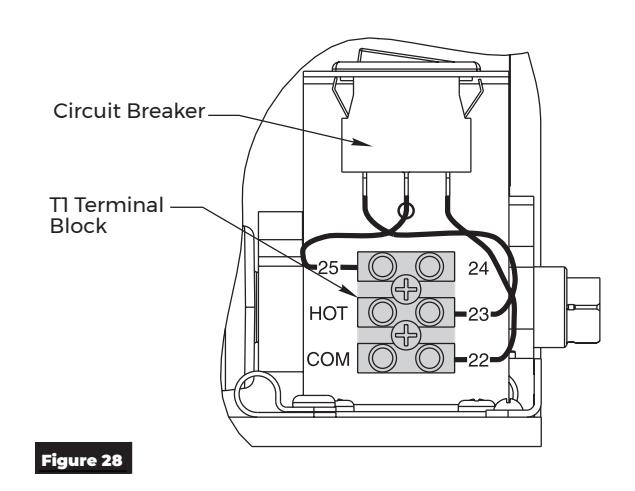

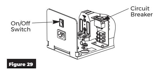
Final Electrical and Mechanical Setup
- 1. Confirm all mechanical adjustments have been made and wiring connected.
- 2. Turn on facility's main circuit breaker.
- 3. Turn on power at On/Off switch and flip breaker switch to "RESET". (Figure 29)
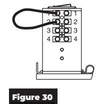
- 4. Using a short jumper cable, jump terminals 1 and 2 to activate unit. When door reaches 20°, flip Breaker Switch to "OFF" position cutting power to unit. Allow door to fully close (door may be manually pulled closed). (Figure 30)
-
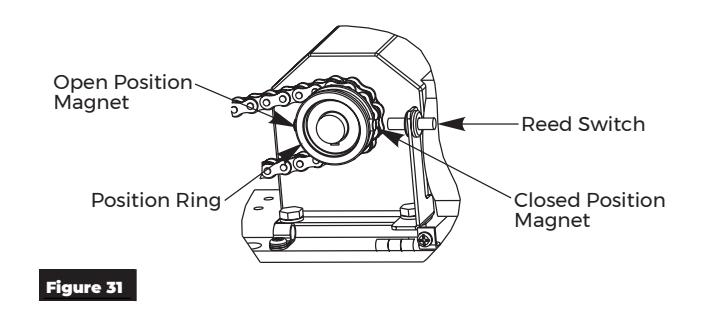
5. Adjust Closing Position Magnet (Figure 31)
- y With door in closed position, use finger to slide Closed Position Magnet so it aligns directly with Reed Switch.
- 6. Adjust Open Position Magnet Use fingers to slide Open Position Magnet 180° from Open Position Magnet.
- 7. Flip Breaker Switch to "RESET" to turn power on.
- 8. Jump terminals 1 and 2 to activate door. Note open position of door. Allow door to close.
- 9. Use finger to readjust Open Position Magnet to desired door open position.
- 10. Repeat Step 7 to verify door open position.
- 11. Make all connections necessary for any accessories to 4-position Accessory Terminal. See Wiring Section.
- 12. Make necessary adjustments to inverter. See Inverter Details Section.

WARNING : 120VAC power supplied to operator must be a dedicated circuit from the main circuit breaker panel and must NOT be connected into any building lighting system that operates fluorescent lights.
The 5700P Operator - PULL SIDE or PUSH SIDE has now been installed. Continue with Electrical Instructions to customize the installation.
13

Attach Cover to finalize installation
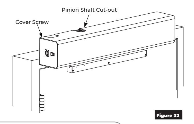
- 1. Align cut-outs in cover to pinion shafts. (Figure 28)
- 2. Slide cover onto unit.
NOTE: Verify all wiring and sheet metal guards are inside cover.
3. Secure cover to backplate with cover screws.
NOTE: If cover will not securely install onto unit, verify backplate is not warped or twisted. Additional support or shimming may be required. See Sections A & B under Prepare Frame and Door.

WARNING : Make sure no wiring is loose or can be caught by cover when it is snapped into place.
Inverter Details
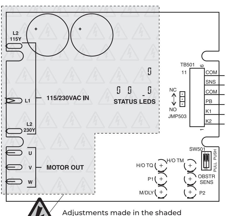
Inverter Adjustments: Use table to determine which POT to adjust based on function.
| POT | Description | Function |
|---|---|---|
| M/DLY | Motor Delay on Opening | |
|
OBSTR
SENS |
Obstruction Detection on
Open |
Clockwise: |
| P1 | Closing Speed | Increase |
| H/O TM |
Hold Open Time (5-30
Secs) |
Counter
Clockwise: |
| H/O TQ |
Motor Torque at Hold Open
Position |
Decrease |
| P2 | Opening Speed |
Adjustments made in the shaded area should be performed by Authorized Factory Personnel.

WARNING : 120 high volt potential present. Make sure power is turned off during installation procedure.

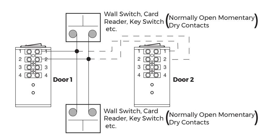
Standard Function With Switches
Operation:
- y Doors are normally closed.
- y Activating either switch will open both doors.
- y Door will close after hold open time delay has elapsed.
NOTES:
- 1. Power input to Door Operator Unit is at "T1" Power Input Terminal (not shown) 120VAC 60Hz.
- 2. Door must be visible by person operating activation switch(es).
Radio Frequency Function Option
Operation:
- y Door is normally closed.
- y Activating wireless switch or hand held wireless transmitter will open door.
- y Door will close after hold open time delay has elapsed.
NOTES:
- 1. Power input to Door Operator Unit is at "T1" Power Input Terminal (not shown) 120VAC 60Hz.
- 2. Radio Frequency feature is purchased as a separate kit.
- 3. Door must be visible by person operating activation switch(es).
15
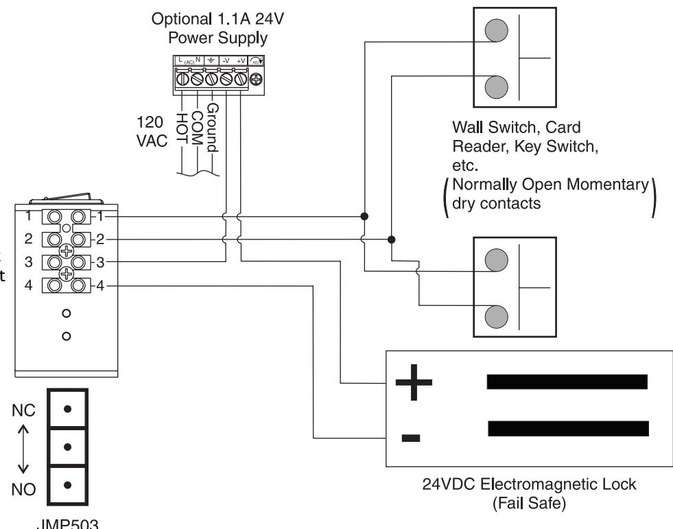
Fail Safe Electromagnetic Lock 24VDC Wiring
Operation:
- y Door is normally closed and latched.
- y Activating switch will cut power to mag lock and door will automatically open.
- y Door will close after hold open time delay has elapsed.
- y Door will unlock during power failure.
NOTES:
- 1. Power input to Door Operator Unit is at "T1" Power Input Terminal (not shown) 120VAC 60Hz.
- 2. Unit Relay Rating: 30VDC @ 1A or 125VAC @ .5A
- 3. Door must be visible by person operating activation switch(es).
Jumper Settings:
Place jumper to upper position for normally closed operation or to lower position for normally open operation.
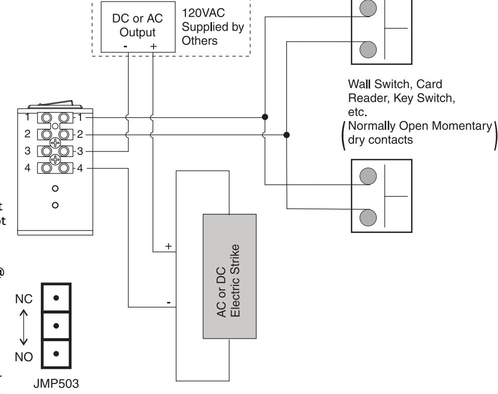
Fail Secure/Fail Safe Electric Strike Wiring
Operation:
- y Door is normally closed and latched.
- y Activating switch will unlock electric strike and door will automatically open.
- y Door will close after hold open time delay has elapsed.
- y For Fail Secure Strike door will remain locked during power failure.
- y For Fail Safe Strike door will remain unlocked during power failure.
NOTES:
- 1. Power input to Door Operator Unit is at "T1" Power Input Terminal (not shown) 120VAC 60Hz.
- 2. Unit Relay Rating for strike interface: 30VDC @ 1A or 125VAC @ .5A
- 3. Door must be visible by person operating activation switch(es).
Jumper Settings:
Place jumper to upper position for normally closed operation or to lower position for normally open operation.

433MHz Receiver User's Guide


In Toggle Setting (1-ON), Hold Time is inactive. Either setting for #2 dip switch will have same result.

0.5 second Pulse Setting

10 second Pulse Setting
| #1 | Description | Function | |
|---|---|---|---|
| OFF | Pulse Relay |
Press transmitter once and relay will be active
momentarily. |
|
| ON | Toggle Relay |
Press transmitter once and relay output is active
indefinitely. Press it again and relay will de-energize indefinitely. |
|
| #2 | Description | Function | |
| OFF | 0.5s Hold Time | Relay will remain active 0.5 sec after loss of activation. | |
| ON | 10s Hold Time | Relay will remain active 10 sec after loss of activation. | |
NOTES:
- y Always stop pedestrian traffic through doorway when performing tests that may result in unexpected reactions by door.
- y Ensure compliance with all applicable safety standards upon completion of installation.
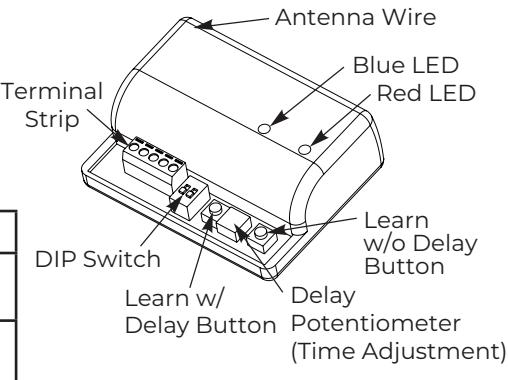
Hand-Held Configuration
- 1. Set dip switches to receiver to desired activation cycle (dip switch 1 - Toggle or Pulse and dip switch 2 - 0.5s or 10s hold).
- 2. Press either Learn w/ Delay Button or Learn w/o Delay Button on receiver depending on activation requirements (if delay learn is selected, adjust potentiometer to counterclockwise limit, 0 second delay). Red LED on receiver will flash. After learn cycle is complete, adjust potentiometer to desired delay time (0 - 30 sec).
- 3. Depress transmitter button repeatedly until Blue LED on receiver illuminates (indicating reception of signal from transmitter).
NOTE: Repeat Steps 2 - 3 to program additional transmitters.
4. To test system, depress transmitter button (Red LED on Transmitter will illuminate) and observe that Blue LED illuminates on receiver. This indicates that relay has been activated.
Push Plate Configuration
- 1. Before beginning, prepare installation of push plate.
- 2. Connect wires from transmitter to NO and COM contacts of push plate's switch.
- 3. Follow Steps 1 4 (Hand-Held Configuration); depress push plate to activate transmitter.
- 4. Attach transmitter to inside of electrical box and complete installation.
Removing Transmitter Code(s) Single Transmitter Code:
- y Press both Delay and No Delay Buttons simultaneously until Red LED flashes once (approximately 1 second).
- y Press transmitter button twice within 10 seconds and transmitter code will be deleted.
All Transmitter Codes:
y Press and hold both Delay and No Delay Buttons simultaneously until Blue LED illuminates then release (approximately 10 seconds).
| Troubleshooting | |||
|---|---|---|---|
|
Problem
Solution |
|||
|
LED on receiver is flickering - unable to
program and/or won't work |
Push plate stuck or faulty transmitter. Disconnect each push plate until LED goes out. If
LED does not go out, remove each transmitter battery until it does. Replace appropriate transmitter. |
||
|
Receiver intermittently doesn't receive
Extend receiver antenna wire only in multiples of 6-3/4" (171) transmitter(s) signal. Example: 6.75 x 4 = 27" (686) of extended antenna wire. |
|||

Troubleshooting Guide
| Problem | Possible Reasons Why | Solution |
|---|---|---|
| Control switch is set to OFF position | Change the setting of the ON/OFF switch | |
| The door does not open | Circuit breaker is set to OFF position | Reset circuit breaker to the ON position |
| - The motor does not start | Electrical power is missing | Check the electrical power switch |
| Activation unit does not function | Jump activation input | |
| Motor is driving in wrong direction |
Flip Door Mounting dip switch to other
direction |
|
| - The motor starts | Something jammed beneath the door | Remove object |
| Arm has come loose | Re-time and re-install arm. | |
| Spring tension too low | Increase spring tension | |
| The door does not close | Arm has come loose | Re-time and re-install arm |
| Something jammed beneath the door | Remove object |

PULL Template

Right hand door opening to 110° shown.
PULL side application is shown.
PUSH side mounting template is provided on page 20.
- y Do not scale drawing.
- y Right hand door shown.
- y All dimensions given in inches (mm).
- y Maximum frame reveal is 1/8" (3mm) for this application.
NOTES:
- 1. Thickness recommended for reinforcements in hollow metal doors and frames is charted on page 4.
- 2. This template information based upon use of 5" (127mm) maximum width butt hinges or 3/4" offset pivots. A separate template is required for other conditions.
- 3. Shaded area = 15" (381mm) maximum distance for placement of power input receptacle.
- 4. Door must be visible by person operating activation switch(es).
|
Door Opening
Angle |
Dim A |
|---|---|
| Up to 110° | 15-1/2" (394mm) |
| 111° to 180° | 13-1/4" (337mm) |
Approved 2024-02-13
The ASSA ABLOY Group is the global leader in access solutions. Every day we help people feel safe, secure and experience a more open world.

ASSA ABLOY
PUSH Template
- Do not scale drawing.
- · Left hand door shown.
- All dimensions given in inches (mm).
- Frame reveal is 2-5/8" 6-3/4" (67-171mm) for this application.
NOTES:
- 1. Thickness recommended for reinforcements in hollow metal doors and frames is charted on page 4.
- 2. This template information based upon use of 5" (127mm) maximum width butt hinges or 3/4" (19mm) offset pivots. A separate template is required for other conditions.
- 3. Shaded area = 15" (381mm) maximum distance for placement of power input receptacle.
- 4. Door must be visible by person operating activation switch(es).
|
Door Opening
Angle |
Dim A | Dim B |
|---|---|---|
| Up to 110° | 12" (305mm) | 15-3/4" (400mm) |
| 111° to 170° | 9-1/2" (241mm) | 13-1/4" (337mm) |
Technical Product Support: Monroe, NC 28112 USA Phone: 877.974.2255 ext: 2
Techsupport.NortonRixson@assaabloy.com
NortonRixson.com