Norton Rixson 5500 Series Operator, 5530 Push Side Installation Instructions_80-9355-0002-020
Open the original PDF document
View PDF5500 Series Power Operator PUSH Side Installation Instructions


! WARNING
This product can expose you to lead which is known to the state of California to cause cancer and birth defects or other reproductive harm. For more information go to www.P65warnings.ca.gov.
Pour la version française voir www.nortondoorcontrols.com. READ AND FOLLOW ALL INSTRUCTIONS. SAVE THESE INSTRUCTIONS.

Contents
| ADA / ANSI / UL 2 | |
|---|---|
| Product Safety Warnings | 2 |
| Components | 3 |
| General Information | 3 |
| Technical Data | 3 |
| Before You Begin | 4 |
| PUSH (Stop) Side Mounting Installation | 5 |
| Adjustments | 8 |
| Input Power Configuration 9 | |
| Final Electrical and Mechanical Setup | 10 |
| Inverter Details | 12 |
| Wiring | 12 |
| Troubleshooting | 14 |
| PUSH (Stop) Side Template | 15 |
ADA / ANSI / UL
- 1. Americans With Disabilities Act (A.D.A.) These door operators can be installed and adjusted to conform with A.D.A. regulations.
- 2. ANSI Standards
ANSI A117.1 – These door operators permit door assemblies to conform to the requirements of this specification "for buildings and facilities – providing accessibility and usability for physically handicapped people".
ANSI A156.19 – These products are designed to conform to this specification "for power assist and low energy power operated doors".
- "PAS" Function is designed to meet or exceed all of the requirements for the "Power Assist Door".
- "POR" Function is designed to meet or exceed all of the requirements for the "Low Energy Power Operated Door".
- 3. U.L. Listing
Underwriters Laboratories, Inc. listed for use on fire and smoke barrier door assemblies when the 120VAC (60Hz) power input is supplied through the normally closed alarm contacts of a compatible UL Listed alarm system or alarm panel.
Product Safety Warnings
WARNING: To reduce risk of injury to person, use this operator only with Pedestrian Swing doors. FOR INDOOR USE ONLY
- 1. READ AND FOLLOW ALL INSTRUCTIONS.
- 2. Install only on a properly operating and balanced door. A door that is operating improperly could cause severe injury. Have qualified service personnel make repairs to any hardware before installing the operator.
- 3. Remove, or make inoperative, all locks (unless mechanically and/or electrically interlocked to the power unit) that are connected to the door before installing the operator.
- 4. Do not connect the door operator to the source power until instructed to do so.
- 5. Never let children operate or play with door controls. Keep
- remote control (when provided) away from children.
- 6. Personnel should keep away from a moving door in motion.
- 7. Test door's features at least once a month. After adjusting either force or limit of travel, retest door operator's features. KEEP DOOR PROPERLY OPERATING. An improperly operating door could cause severe injury or death.
- 8. Maximum door size: 48" (1219mm) wide x 250 lb (113.4kg)
- 9. SAVE THESE INSTRUCTIONS.

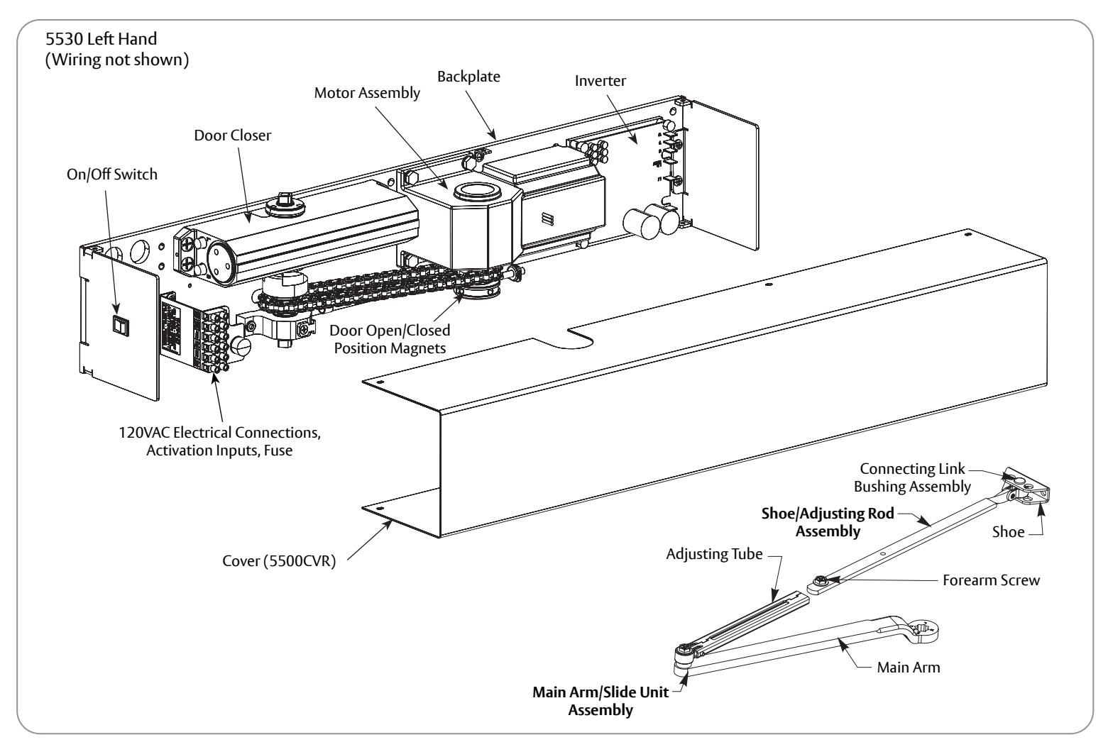
Components
General Information
- UL labeled fire or smoke barrier door assemblies require that the 120VAC (60Hz) power input to the 5500 door operator be supplied through normally closed alarm contacts of the alarm system / alarm panel.
- Power input to 5500 door operator must be 120VAC (60Hz) to terminals HOT and COM at Power Inputs terminal strip. Earth ground (GND) to green screw on backplate.
- All wiring must conform to standard wiring practice in accordance with national and local wiring codes.
- Unit is Non-Handed.
- Door must swing freely through the entire opening and closing cycle before beginning the installation.
- Use of an auxiliary door stop (by others) is always recommended.
- An incorrectly installed or improperly adjusted door operator can cause property damage or personal injury. These instructions should be followed to avoid the possibility of misapplication or misadjustment.
Technical Data
| Input power: | 120VAC, 60Hz |
|---|---|
| Power consumption: | .6 amps |
| Fuse: | 3 amps |
| Door width: | 28" - 48" Max. (71-122 cm) |
| Door weight: | 100-250 lb Max. (43-113 kg) |
| Door opening angle: | up to 170°; Manually to 180° |
| Hold open time: | 5-30 seconds (A.D.A. 5 seconds min.) |
Notes:
- Permanent wiring is to be implemented as required by local codes.
- Activation devices: push plates, access control, mats, touchless wall switches, etc.
- Maximum wire size is: 12AWG at terminals HOT and COM (120VAC; 60Hz) 14AWG at terminals A1, A2, R1, R2
- Rate of operation shall not exceed 300 cycles of opening and closing per hour.

WARNING: Make sure (120V, 60Hz) input power is turned OFF at facility's main circuit breaker before proceeding with installation

Before You Begin
- All dimensions are given in inches (millimeters). DO NOT scale drawings.
- Thickness recommended for reinforcements in hollow metal doors and frames is charted.
- Template information is based on use of 5" (127mm) maximum width butt hinges or 3/4" (19mm) offset pivots.
- Frame reveal is between 2-5/8" and 6-3/4" (67-171mm) for PUSH units.
- Before beginning the installation, verify that the door frame is properly reinforced and is well anchored in the wall. Frame header must be straight - without warp or bow.
- Unreinforced hollow metal frames and aluminum frames should be prepared and fitted with 1/4-20 blind rivet nuts, furnished by others.
- Concealed electrical conduit and concealed switch or sensor wires should be pulled to the frame before proceeding.
Fasteners for Frame:
- Hollow metal and aluminum: 1/4-20 Machine screws
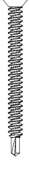
- Wood: No. 14 x 2-3/4" (70mm) sheet metal screws
Fasteners for Door (Push Side Mounting):
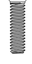
• 1/4-20 Machine screws 3/8 x 1-5/8" sex nut
| Hollow Metal Door Frame Reinforcing | |||
| Reinforcing | |||
| Frame Material | Recommended | Min. Required | |
| 12 Ga. | 12 Ga. | 18 Ga. | |
| .105 | .105 | .048 | |
| (2.66) | (2.66) | (1.21) | |
| 14 Ga. | 10 Ga. | 12 Ga. | |
| .075 | .134 | .105 | |
| (1.90) | (3.41) | (2.66) | |
| 16 Ga. | 10 Ga. | 12 Ga. | |
| .060 | .134 | .105 | |
| (1.52) | (3.41) | (2.66) | |
| 18 Ga. | 8 Ga. | 10 Ga. | |
| .048 | .164 | .134 | |
| (1.21) | (4.18) | (3.41) | |
| Mounting Hardware | Door or Frame | Drill | |
|---|---|---|---|
|
Unit:
14 x 2-3/4" Sheet Metal Screw |
Wood | 3/16" (4.76mm) | |
|
Unit:
1/4-20 x 1" Flat Head Machine Screw |
Hollow Metal or
Aluminum |
Drill #7 (.201 dia. or 5.10mm)
Tap 1/4-20 |
|
|
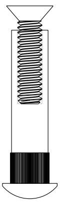
Arm:
1/4-20 x 2" Sex Nut and Bolt (SNB) |
Hollow Metal |
9/32" (7.00mm) thru
3/8" (9.50mm) door face opposite to closer |
|
| Aluminum or Wood | 3/8" (9.50mm) thru | ||
80-9355-0002-020 Rev 1 08/20

Prepare Frame and Door for PUSH Side Installation
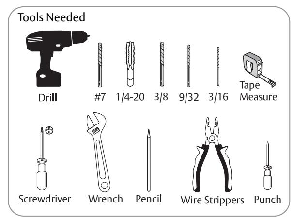
Become familiar with operator components and fasteners. It is recommended that components remain in box until installed. Verify there is minimum ceiling clearance for operator installation before proceeding. (Figure 1)
A. Prepare frame for operator.
Verify frame reveal width is 2-5/8"-6-3/4" (67mm-171mm). (Figure 1)
NOTE: If frame reveal is less than 3" (76mm), arm adjusting rod can be field cut to 9-1/2" (241mm) measured from centerline of connecting link bushing assembly.
2. Determine if push or pull and if left hand or right hand installation. (Figure 2)

NOTE: These steps are for PUSH side only.
Frame header MUST be flat / without twists. Backplate of operator can be used as reference.
NOTE: If frame is not flat or is twisted, an additional steel back plate or shimming is required. Failure to mount unit properly can result in improper function of operator.
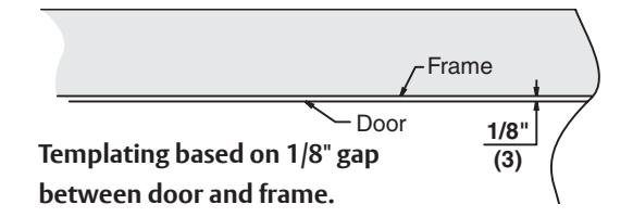
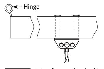
- Using detailed template on page 15, prepare four (4) holes for 1/4-20 machine screws or 14 x 2-3/4" wood screws. Blind rivet nut (by others) is suggested for unreinforced hollow metal or aluminum frames. (Figure 3)
- For concealed mounted conduit (if applicable): Prepare two (2) 7/8" (22mm) diameter holes for conduit, for power input and for switch/ sensor wires.
NOTE: On new construction, these holes will generally be drilled by frame supplier at their shop or at time-of-install.
| Door Opening Angle | Dim B |
|---|---|
| Up to 110° | 15-3/4" (400mm) |
| 111° to 170° | 13-1/4" (337mm) |
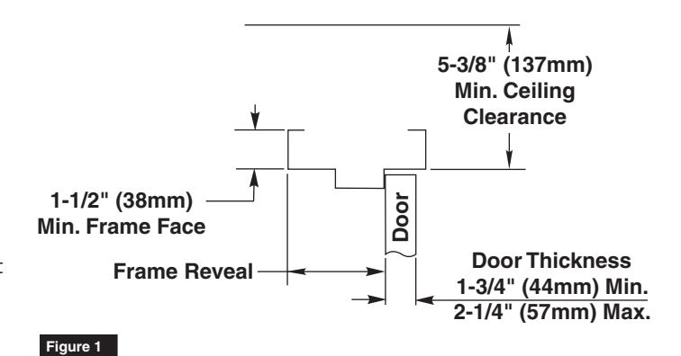
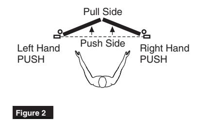
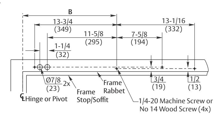
Figure 3 Left Hand Shown


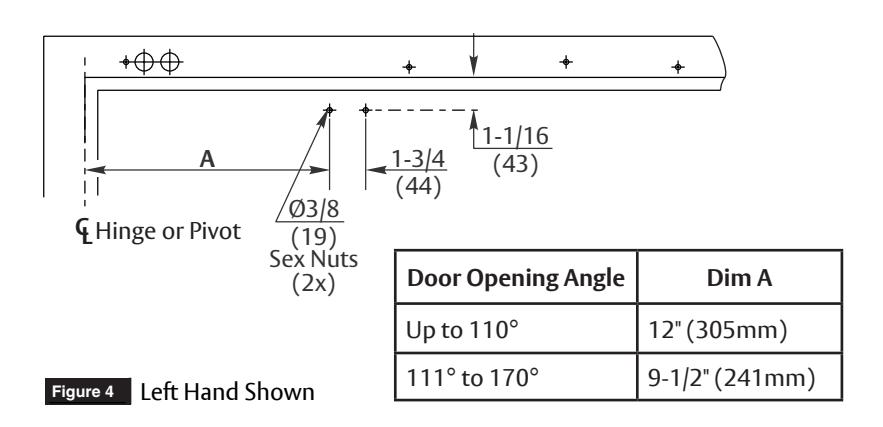
B. Prepare door for arm assembly.
1. Using template on page 15, locate and prepare two (2) 3/8" (9.5mm) holes in door for sex bolts. (Figure 4)
NOTE: Standard units are supplied with sex nuts and bolts for 1-3/4" (44mm) thick door. Sex nuts and bolts for other door thicknesses are available to order.
Install Operator
A. Remove cover from unit and set cover and screws aside.

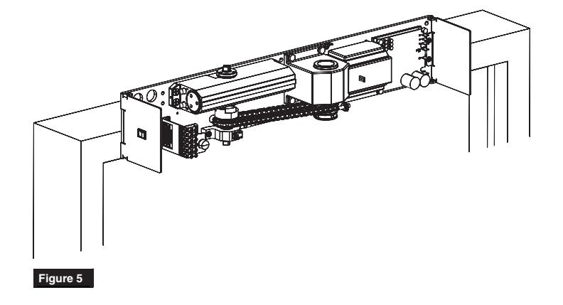
B. Mount unit to frame. (Figure 5)
NOTE: Select Concealed or Surface option.

- Connect conduit to frame side of backplate.
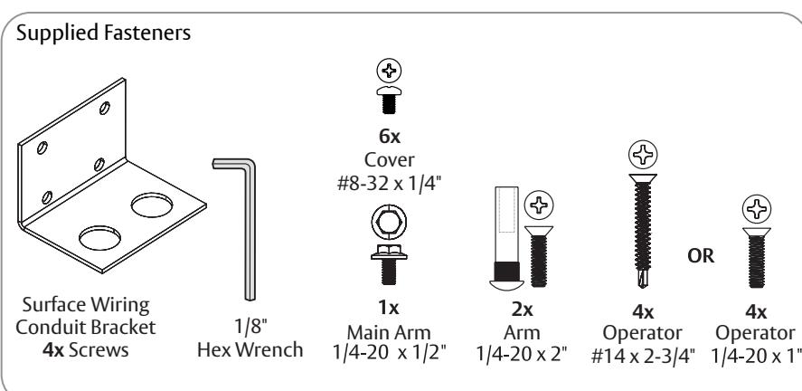
- Secure unit to frame with four (4) 1/4-20 x 1" FHMS or #14 x 2-3/4" FHSM screws.

- Secure unit to frame with four (4) 1/4-20 x 1" FHMS or #14 x 2-3/4" FHSM screws.
- Mount conduit bracket (found in screw pack) to unit backplate with four (4) provided screws.
- Connect wiring conduit to bracket.
OR


Install Arm
A. Mount forearm shoe to door.
1. Using previously prepared holes in door, install two (2) 1/4-20 x 1-5/8" screws through shoe and into sex bolts. (Figure 6)

B. Install main arm to operator.
1. Insert main arm onto pinion shaft of unit at 90° angle to frame. (Figure 7)
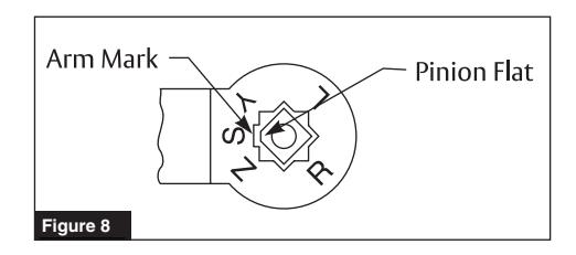
NOTE: Align arm mark "S" with flat corner of pinion shaft square. (Figure 8)
2. Secure main arm to pinion with 1/4-20 x 1/2" flange head screw.
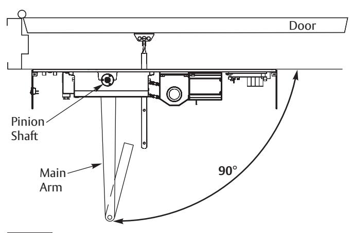
Figure 7 View from ceiling looking downward
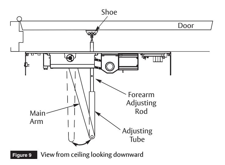
C. Preload arm.
- 1. Open door.
- 2. Remove 1/4-20 hex head screw on forearm adjusting rod. (Figure 9)
- 3. Insert adjusting rod into adjusting tube. (Figure 9)
- 4. Reinstall 1/4-20 screw and leave loose.
- 5. Rotate main arm in direction away from hinge edge until adjusting rod and tube are perpendicular (at 90° angle) to frame.
- 6. Tighten 1/4-20 hex head screw on adjusting rod to secure arm in this new position.

Adjustments
A. Adjust mechanical closer features.
NOTE:
- • Make necessary mechanical adjustments so unit functions as a standard surface mounted door closer before adjusting spring force, applying power, adding accessories or making electrical/programming adjustments.
- • Refer to table for recommended minimum opening/closing times per ANSI/BHMA A156.19. (Figure 12)
- • Use hex wrench to make adjustments.

Do not remove valves from closer. Hydraulic oil will escape.
-
1. Closing Speed Controls (Figure 10)
- Valve "S" controls Sweep Range from full open to 10°.
- Valve "L" controls Latch Range from 10° to closed.
-
2. Opening Cycle (Figure 11)
- Valve "BC" controls strength of cushioning in Backcheck Range.

NOTE: Too much backcheck can affect operation of unit pump, preventing full open of door. This valve may require fine tuning after all other adjustments have been made.

NOTE:
- • The amount of effort to manually open or close a door is called force and is controlled by the operator's closer spring.
- • Make necessary mechanical adjustments described in "A" above.
- • A closer set to ADA required 5 lbs opening force may not be strong enough to close door due to latching hardware, air pressure, or frame issues.
- 1. Using 1/8" hex wrench, turn power adjustment screw clockwise to increase door closing power. (Figure 13)
NOTE: Door control is shipped set at midpoint of power setting. Maximum closing power can be achieved with 8 (360°) clockwise turns of power adjustment screw.
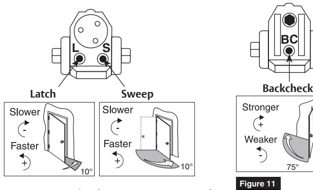
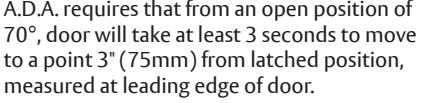
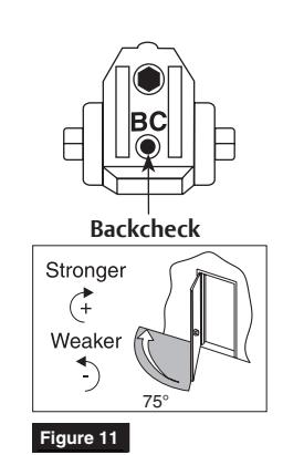
Figure 10
| ANSI/BHMA A156.19 Minimum Opening/Closing Times | |||||
|---|---|---|---|---|---|
| Door Leaf | Door Weight - Pounds (kg) | ||||
|
Width
Inches (mm) |
100
(45.4) |
125
(56.7) |
150
(68.0) |
175
(79.4) |
200
(90.7) |
| 30" (762) | 3.0 sec | 3.0 sec | 3.0 sec | 3.0 sec | 3.5 sec |
| 36" (914) | 3.0 sec | 3.5 sec | 3.5 sec | 4.0 sec | 4.0 sec |
| 42" (1067) | 3.5 sec | 4.0 sec | 4.0 sec | 4.5 sec | 4.5 sec |
| 48" (1219) | 4.0 sec | 4.5 sec | 4.5 sec | 5.0 sec | 5.5 sec |
Backcheck: Adjust backcheck to have minimum opening time to backcheck or 80 degrees (whichever comes first) based on Table.
Closing Time: Adjust latch and sweep to have minimum closing time from 90 degrees to latch check or 10 degrees (whichever comes first) based on Table.
Figure 12

Input Power Configuration
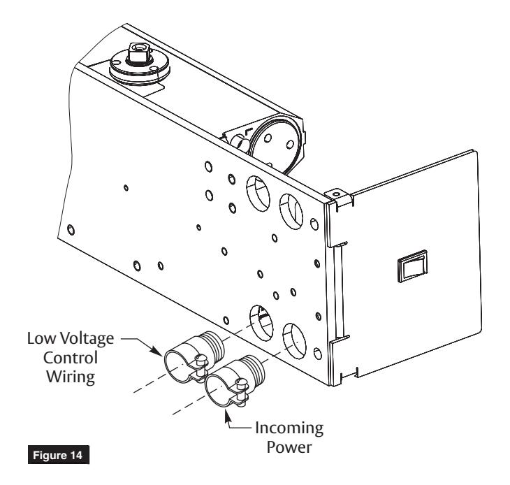
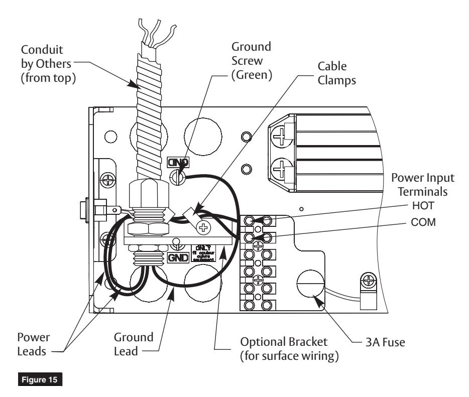
Thread conduit fitting(s) into backplate. Concealed Wiring (Figure 14) Surface Wiring (Figure 15)
NOTE:
- A second conduit fitting is required for low voltage control wiring.
- · Check local codes.
- 2. Pull conduit out of header and attach to conduit fittings before mounting unit.
- 3. After installing operator, attach incoming ground wire to backplate with ground screw as illustrated. (Figure 15)
NOTE: Ground wire must be secured to backplate under head of (green) ground screw.

Final Electrical and Mechanical Setup
- 1. Confirm all mechanical adjustments have been made and wiring connected.
- 2. Turn on facility's main circuit breaker.
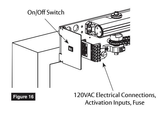
- 3. Turn on power of operator at On/Off switch. (Figure 16)
- 4. Using a short jumper cable, jump terminals A1 and A2 to activate unit. When door reaches 20°, flip On/Off Switch to "OFF" position cutting power to unit. Allow door to fully close (door may be manually pulled closed).
-
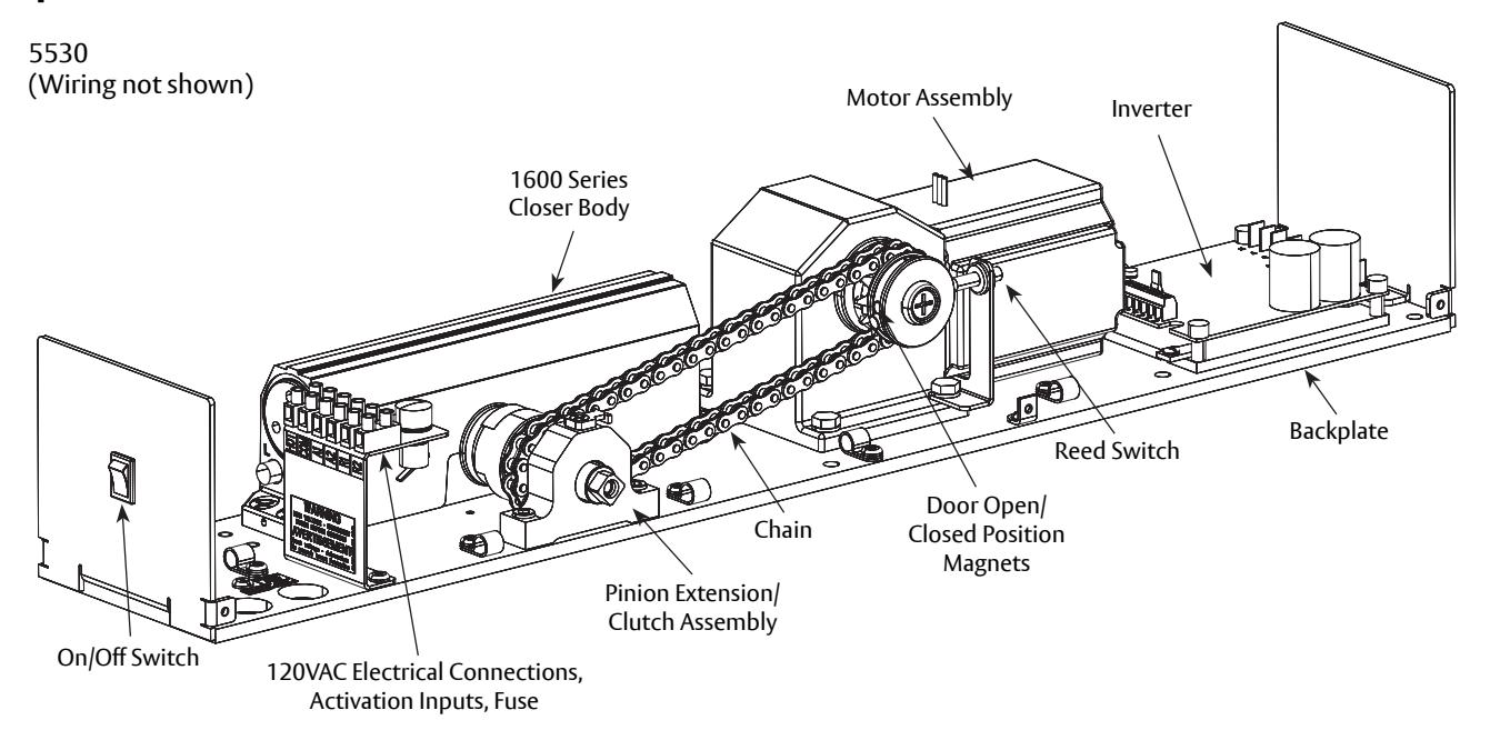
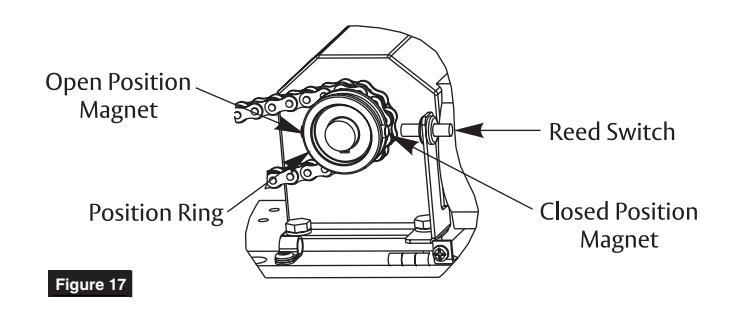
5. Adjust Closed Position Magnet (Figure 17)
- With door in closed position, use finger to slide Closed Position Magnet so it aligns directly with Reed Switch.
-
6. Adjust Open Position Magnet (Figure 17)
- Use finger to slide Open Position Magnet 180° from Closed Position Magnet.
- 7. Flip On/Off Switch to "ON" to turn power on.
- 8. Jump terminals A1 and A2 to activate door. Note open position of door. Allow door to close.
- 9. Use finger to readjust Open Position Magnet to desired door open position.
- 10. Repeat Step 7 to verify door open position.
- 11. Make all connections necessary for any accessories to A1, A2, R1, and R2 on terminal strip. See Wiring Section.
- 12. Make necessary adjustments to inverter. See Inverter Details Section.

WARNING: 120VAC power supplied to operator must be a dedicated circuit from the main circuit breaker panel and must NOT be connected into any building lighting system that operates fluorescent lights.
You've now installed the 5500 Operator - PUSH SIDE.
Continue with Electrical Instructions to customize the installation.

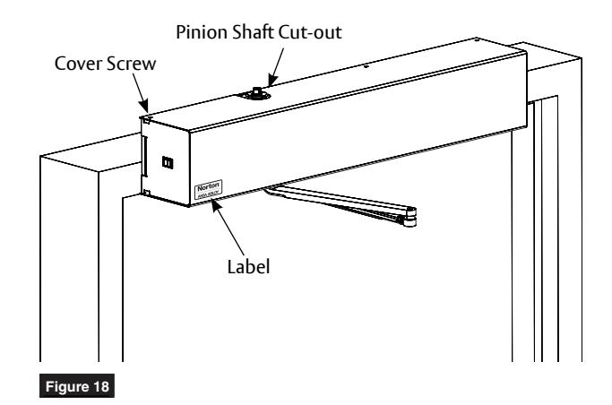
Attach Cover and Label to finalize installation
- 1. Align cut-outs in cover to pinion shafts. (Figure 18)
- 2. Slide cover onto unit.
NOTE: Verify all wiring is inside cover.
3. Secure cover to backplate with six (6) cover screws.
NOTE: If cover will not securely install onto unit, verify backplate is not warped or twisted. Additional support or shimming may be required. See Sections A & B under Prepare Frame and Door.
4. Attach Norton label to front of cover approximately 1/2" (13mm) from side and bottom edges.

WARNING: Make sure no wiring is loose or can be caught by cover when it is snapped into place.

Inverter Details
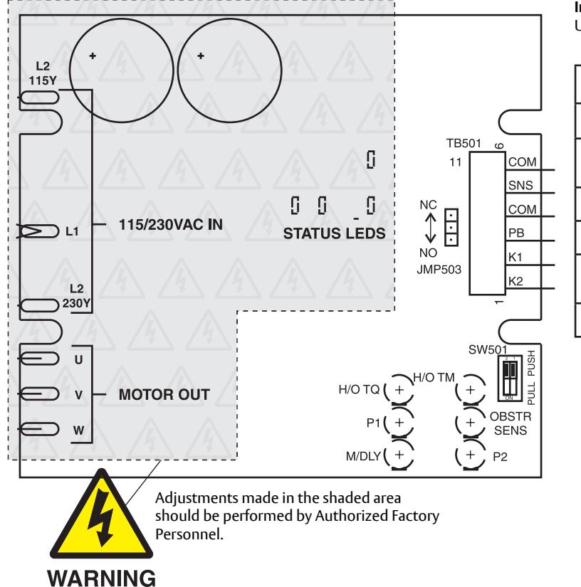
Inverter Adjustments:
Use table to determine which POT to adjust based on function.
| POT | Description | Function | |
|---|---|---|---|
| M/DLY | Motor Delay on Opening | ||
| OBSTR SENS |
Obstruction Detection on
Open |
Clockwise: | |
| P1 | Closing Speed | Increase | |
| H/O TM | Hold Open Time (5-30 Secs) | Counter | |
| H/O TQ |
Motor Torque at Hold Open
Position |
Clockwise:
Decrease |
|
| P2 | Opening Speed | ||


WARNING: 120 high volt potential present. Make sure power is turned off during installation procedure.
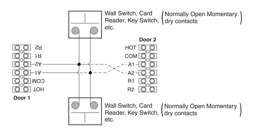
Standard Function With Switches Wiring
Operation:
- Doors are normally closed.
- Activating either switch will open both doors.
- Door will close after hold open time delay has elapsed.
NOTE:
- 1. Power input to Door Operator Unit is at HOT/COM on terminal strip shown 120VAC 60Hz.
- 2. Door must be visible by person operating activation switch(es).

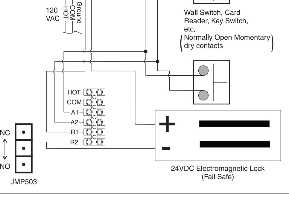
Fail Safe Electromagnetic Lock 24VDC Wiring
Operation:
- Door is normally closed and latched.
- Activating switch will cut power to mag lock and door will automatically open.
- Door will close after hold open time delay has elapsed.
- Door will unlock during power failure.
NOTE:
- 1. Power input to Door Operator Unit is at HOT/COM on terminal strip shown 120VAC 60Hz.
- 2. Unit Relay Rating: 30VDC @ 1A or 125VAC @ .5A
- 3. Door must be visible by person operating activation switch(es).
Jumper Settings:
Place jumper to upper position for normally closed operation or to lower position for normally open operation.
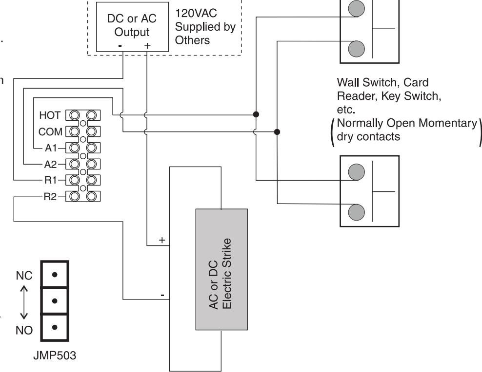
Fail Secure/Fail Safe Electric Strike Wiring
Operation:
- Door is normally closed and latched.
- Activating switch will unlock electric strike and door will automatically open.
- Door will close after hold open time delay has elapsed.
- • For Fail Secure Strike - door will remain locked during power failure.
- • For Fail Safe Strike - door will remain unlocked during power failure.
NOTE:
- 1. Power input to Door Operator Unit is at HOT/COM on terminal strip shown 120VAC 60Hz.
- 2. Unit Relay Rating for strike interface: 30VDC @ 1A or 125VAC @ .5A
- 3. Door must be visible by person operating activation switch(es).
Jumper Settings:
Place jumper to upper position for normally closed operation or to lower position for normally open operation.

Troubleshooting
| Problem | Possible Reasons Why | Solution | |
|---|---|---|---|
| Control switch is set to OFF position | Change the setting of the ON/OFF switch | ||
| The door does not open | 3A fuse in fuse holder is blown | Replace fuse: 3A - 5mm x 20mm glass fuse | |
| - The motor does not start | Electrical power is missing | Check the electrical power switch | |
| Activation unit does not function | Jump activation input | ||
| Motor is driving in wrong direction | Flip Door Mounting dip switch to other direction | ||
| - The motor starts | Something jammed beneath the door | Remove object | |
| Arm has come loose | Re-time and re-install arm | ||
| Spring tension too low | Increase spring tension | ||
| The door does not close | Arm has come loose | Re-time and re-install arm | |
| Something jammed beneath the door | Remove object | ||

PUSH Template

Left hand door opening to 110° shown.
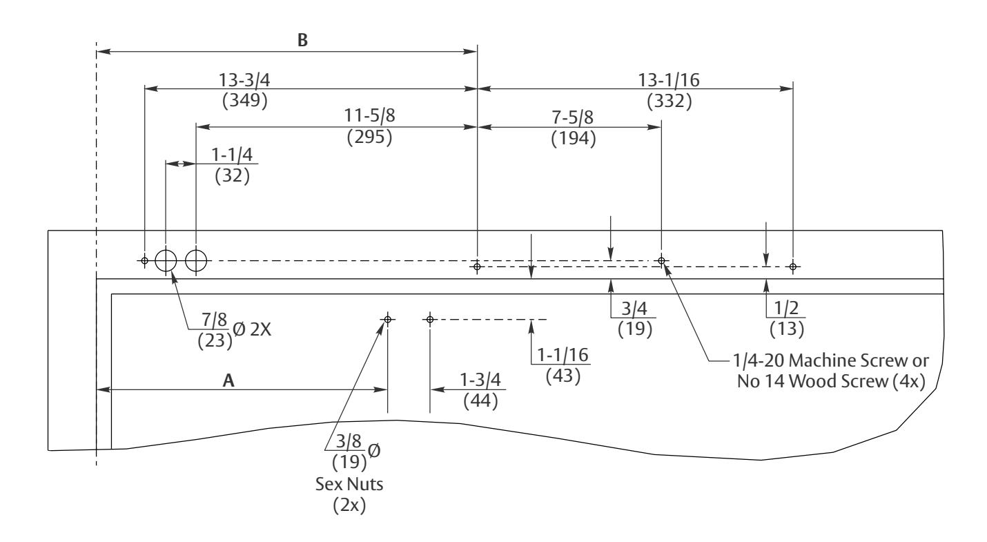
- Do not scale drawing.
- Left hand door shown.
- All dimensions given in inches (mm).
- Frame reveal is 2-5/8"-6-3/4" (67mm-171mm) for this application.
Notes:
- 1. Thickness recommended for reinforcements in hollow metal doors and frames is charted on page 4.
- 2. This template information based upon use of 5" (127mm) maximum width butt hinges or 3/4" (19mm) offset pivots. A separate template is required for other conditions.
- 3. Conduit hole nearest hinge is suggested for 120 VAC power input.
- 4. Door must be visible by person operating activation switch(es).
| Door Opening Angle | Dim A | Dim B |
|---|---|---|
| Up to 110° | 12" (305mm) | 15-3/4" (400mm) |
| 111° to 170° | 9-1/2" (241mm) | 13-1/4" (337mm) |

Norton Technical Product Support: Monroe, NC 28112 USA Phone: 800.438.1951 ext: 6030 TechSupport.Norton@assaabloy.com