Norton Rixson 5200 Series 5241 Low Energy Operator Push Side Installation Instructions_80-9352-0026-020
Open the original PDF document
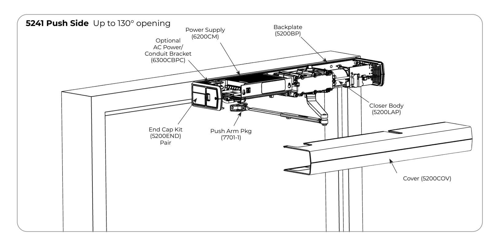
View PDF5200 Series Full Feature Low Energy Operator
Model 5241 (Push Side) Installation Instructions


This product can expose you to lead which is known to the state of California to cause cancer and birth defects or other reproductive harm. For more information go to www.P65warnings.ca.gov.
Pour la version française voir NortonRixson.com. READ AND FOLLOW ALL INSTRUCTIONS. SAVE THESE INSTRUCTIONS.
The table below provides a list of documents associated with this product. These documents are available for download from www.nortonrixson.com. If additional information or assistance is needed, contact Technical Product Support.
| Document Title | Document Number |
|---|---|
| 5200 Series Programming Instructions | 80-9352-0022-020 |
| 5231 Push Side Template | 80-7352-0002-020 |

Contents
| Certifications and Standards 2 | |
|---|---|
|
Technical Data
|
2 |
| Product Safety Warnings 2 | |
| Before You Begin 3 | |
| Installation | 3 |
| Template | 8 |
Certifications and Standards
- y ETL Certified: Operator conforms to ANSI/UL standard 325 for automatic closing doors.
- y ANSI A156.19: These products are designed to conform to this specification "for power assist and low energy power operated doors." These products are designed to exceed all the requirements for "Low Energy Power Operated Door".
- y Americans with Disabilities Act (A.D.A.): These door operators can be installed and adjusted to conform with A.D.A. regulations.
- y ANSI A117.1: These door controls permit door assemblies to conform to the requirements of this specification "for buildings and facilities - providing accessibility and usability for physically disabled people".
Technical Data
| Input power: | 120VAC, 60Hz 3.0A | NOTES: | |
| Power supply: |
24 V DC, max. 4.5 Amp. ; .4A Available for
Acc. |
||
| Door width: | 36 - 48" (91-122 cm) | ||
| Door weight: | 90-200 lb. (41-91 kg) | ||
| Push max angle: |
130° with reveal of 1/8" to 3-1/4" (3 to 82.5
mm) |
||
| Pull max angle: | 120° | ||
| Hold open time: |
5-30 seconds (A.D.A. 5 seconds min.)
Indefinite for Hold Open Input or End Cap 3 Position Switch |
||
- y Permanent wiring is to be employed as required by local codes.
- y Activation devices: push plates, touchless wall switches, etc.
-
y Maximum wire size is:
- ‒ 12AWG at terminals LINE and NEUTRAL
- ‒ (120VAC; 60Hz) on Power Input Terminal
- ‒ 14AWG at all other terminals
Product Safety Warnings
WARNING: To reduce risk of injury to person, use this operator only with Pedestrian Swing doors. FOR INDOOR USE ONLY
- 1. READ AND FOLLOW ALL INSTRUCTIONS.
- 2. Install only on a properly operating and balanced door. A door that is operating improperly could cause severe injury. Have qualified service personnel make repairs to any hardware before installing the operator.
- 3. Remove, or make inoperative, all locks and latches that could prevent the operator from opening the door. The operator is capable of powering a retracting latch or other exit devices to enhance the security of the opening.
- 4. Do not connect the door operator to the source power until instructed to do so.
- 5. Never let children operate or play with door controls. Keep remote control (when provided) away from children.
- 6. Personnel should keep away from a moving door in motion.
- 7. Test door's safety features at least once a month. After adjusting either force or limit of travel, retest door operator's safety features. Failure to adjust operator properly may cause severe injury or death.
- 8. KEEP DOOR PROPERLY OPERATING. See Door Manufacturer's Owner's Manual. An improperly operating door could cause severe injury or death. Have a trained door systems technician make repairs.
- 9. SAVE THESE INSTRUCTIONS.

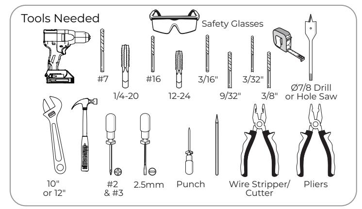
Before You Begin
- Thickness recommended for reinforcements in hollow metal doors and frames is as shown in the chart
- This template information is based on use of 5" (127mm) maximum width butt hinges.
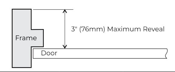
- Maximum frame reveal is 3" for 5241 Series units.
- Before beginning the installation, verify that the door frame is properly reinforced and is well anchored in the wall.
For concealed wiring:
- Use template (available for download from www.nortonrixson.com) to drill conduit holes in the door frame, prior to running concealed electrical conduit and switch/sensor wires.
- Wires should be pulled through the frame prior to operator installation.
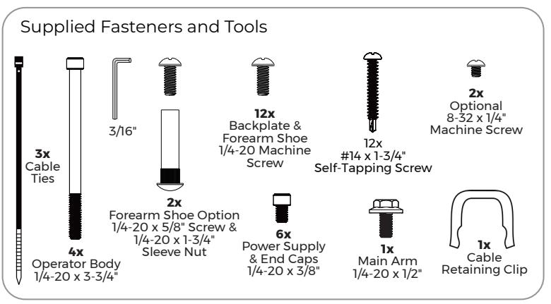
Fasteners for Frame:
- 1/4-20 Machine screws for hollow metal and aluminum.
- #14 x 1-3/4" self-drilling, self tapping screws for wood.
Installation
A. Mount backplate.
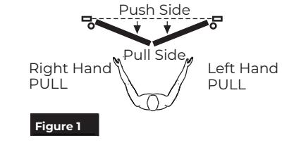
- 1. Determine right hand or left hand installation. (Figure 1)
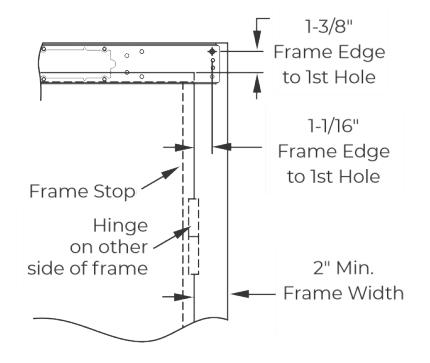
- 2. Measure, mark, and drill the first mounting hole according to the template (available for download from www.nortonrixson.com). (Figure 2)
OR
For Metal Frames:
Use #7 drill and 1/4-20 tap for 1/4-20 machine screws.
For Wood Frames:
Use 3/16" drill and supplied screws for self drilling, self tapping screws.
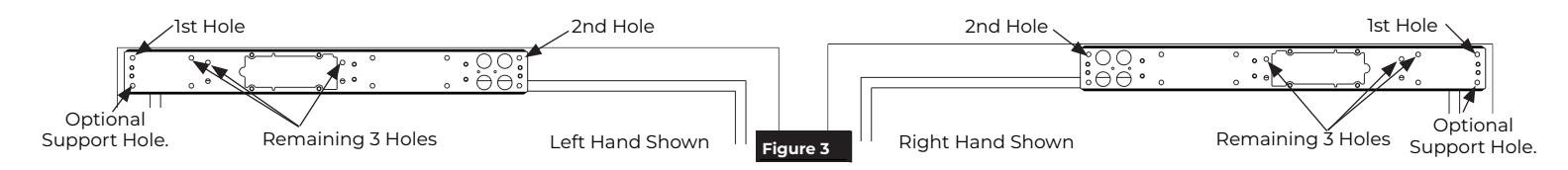
- Place backplate against the frame so that the first hole in the backplate is aligned with the first mounting hole in the frame. Attach backplate to the frame with the provided screw. Do not fully tighten the screw at this time. (Figure 3)
- Ensure the backplate is aligned with the door frame. Using the backplate as a guide, mark and drill the second mounting hole. (Figure 3)
- 5. Insert the second screw and tighten both screws.
- 6. Using the backplate as a guide, drill and tap the remaining three (3) holes in the frame. (Figure 3)
- 7. Secure the backplate with three (3) additional screws and securely tighten all screws.
Optional : Drill and tap the additional mounting hole in the frame for added support and secure with an additional screw.(Figure 3)
8. For concealed wiring : Using the backplate as a guide, mark and pre-drill two (2) conduit holes with the 3/16" drill. Then use the Ø7/8" hole saw or equivalent to drill two (2) conduit holes.
| Hollow Metal Door Frame Reinforcing | ||||
|---|---|---|---|---|
| Frame Material | Reinforcing | |||
| Recommended | Min. Required | |||
| 12 Ga. | 12 Ga. | 18 Ga. | ||
| .105 | .105 | .048 | ||
| (2.66) | (2.66) | (1.21) | ||
| 14 Ga. | 10 Ga. | 12 Ga. | ||
| .075 | .134 | .105 | ||
| (1.90) | (3.41) | (2.66) | ||
| 16 Ga. | 10 Ga. | 12 Ga. | ||
| .060 | .134 | .105 | ||
| (1.52) | (3.41) | (2.66) | ||
| 18 Ga. | 8 Ga. | 10 Ga. | ||
| .048 | .165 | .134 | ||
| (1.21) | (4.18) | (3.41) | ||


B. Mount the forearm with shoe.
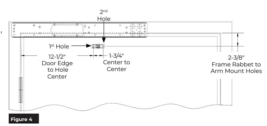
1. Using the template (available for download from www.nortonrixson.com), measure and mark the door for the first forearm shoe mounting hole. (Figure 4)

2. Drill the first mounting hole:


Reference Figure 5 and use 1/4-20 x 5/8" screws with sleeve nuts.
- 3. Secure the forearm shoe to the first mounting hole using a 1/4-20 x 5/8" screw. Do not fully tighten.
- 4. Level the forearm shoe on the door.
- 5. Using the forearm shoe as template, mark and drill the second mounting hole. (Figure 4)
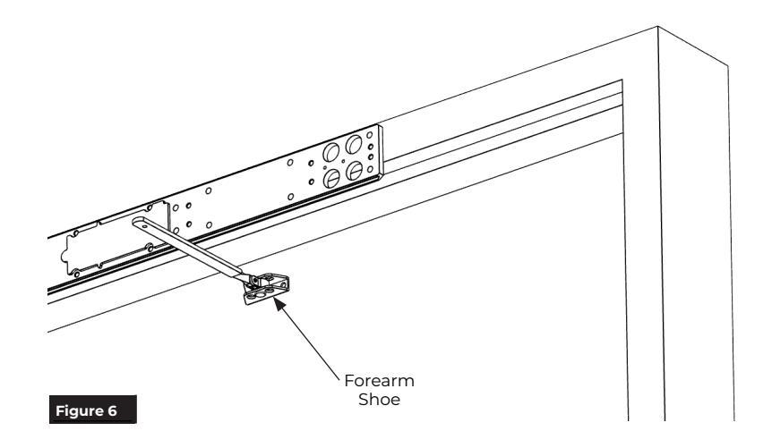
- 6. Repeat step 3 and secure the forearm shoe to door. Tighten both screws. (Figure 6)
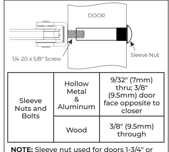
NOTE: Sleeve nut used for doors 1-3/4" or greater. For doors less than 1-3/4", sleeve nut body will need to be shortened.
Figure 5

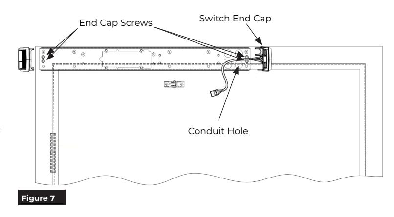
C. Install the end caps.
- 1. Install two (2) screws on each end of backplate, leaving an approximate 3/16" gap between the head of the screw and the backplate. (Figure 7)
- 2. Slide the end caps behind the screw heads and tighten both screws. (Figure 7)
NOTE: The end cap with the 3-position switch is always located on the conduit hole side of backplate.
D. Install the closer body assembly.
1. Using the four (4) screws provided, install the operator body to the backplate. (Figure 8)
NOTES:
- y Tighten screws in a cross pattern until all four (4) screws are tight. (Figure 8)
-
y The operator body is properly orientated for PUSH SIDE application when:
- The motor is toward the hinge side of the door.
- The connector board is facing way from the backplate.
- "This side out PUSH SIDE" label is facing away from the backplate. (Figure 8)
- 2. Using the supplied cable management clip, secure the cables along operator body. (Figure 9)
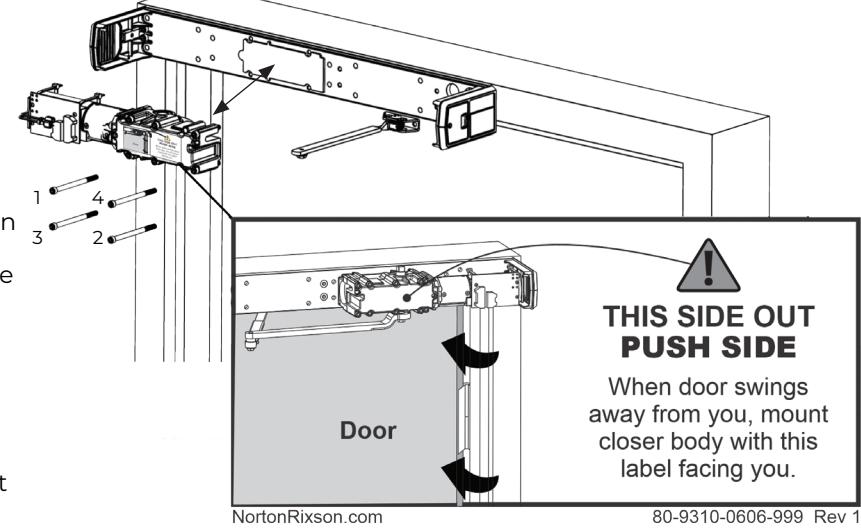
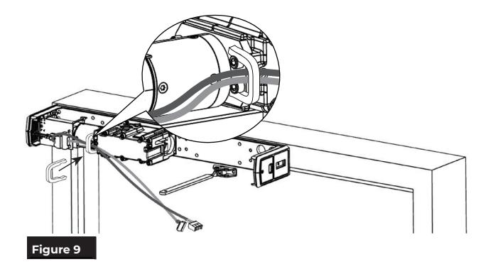
Figure 8 Left Hand Shown

E. Install the power supply assembly.
1. Insert two (2) 1/4-20 x 3/8" screws as shown, leaving an approximate 3/16" gap between the head of the screws and backplate. (Figure 10)
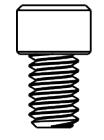
2. Slide the power supply key holes over screws allowing narrow slots of key holes to rest on the screws. (Figure 10)
NOTE: To properly orientate the power supply:
- ‒ The narrow slots of key holes are at the top.
- ‒ The control board always faces down.
- ‒ The power supply harness faces the switch end cap.
- 3. Tighten both screws.
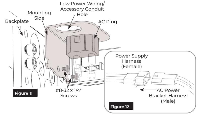
- 4. Optional: AC conduit bracket assembly installation.

- ‒ Place the AC Plug conduit bracket against the backplate with the AC plug and conduit hole facing up toward the frame header. The mounting side of the bracket will face the backplate. (Figure 11)
- ‒ Secure the bracket to the backplate using two (2) #8-32 x 1/4" machine screws.
- ‒ Plug the bracket's wiring harness into the pre-wired AC harness of the power supply. (Figure 12)
-
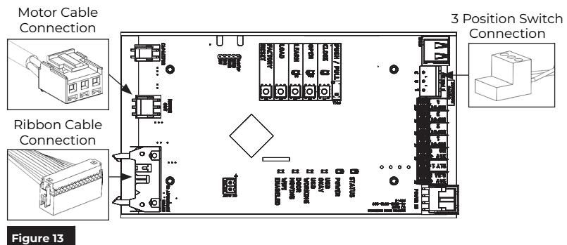
5. Connect the motor cable and ribbon cable from the operator body to the power supply control board. (Figure 13)
- ‒ To connect the ribbon cable, spread the tabs on the control board connector before inserting.
- 6. Connect the 3-position switch to the power supply. (Figure 13).

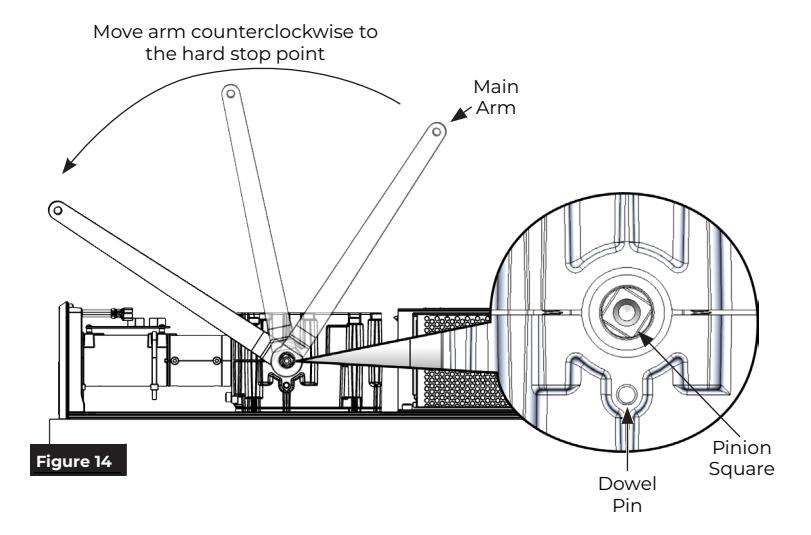
F. Set pinion to starting position.
- 1. Locate the dowel pin on the side of the operator housing (adjacent to the pinion square). (Figure 14)
- 2. Place the main arm on the pinion square and rotate it counterclockwise until the pinion comes to a hard stop.

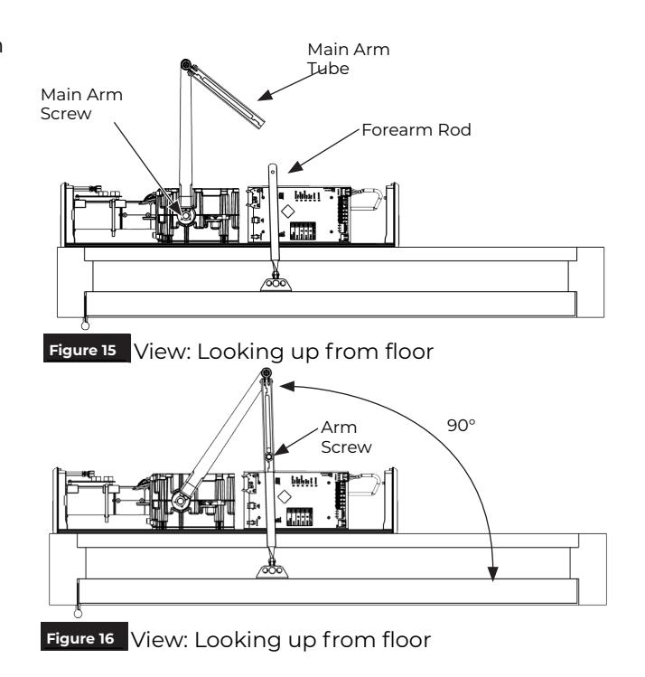
G. Install main arm.
- 1. Using an adjustable wrench, secure the main arm to bottom pinion with the 1/4-20x 1/2" screw. (Figure 16)
- 2. Slide the main arm tube onto the forearm rod. (Figure 16)
NOTE: If necessary, open the door to allow the tube to slide onto forearm.
- 3. With door fully closed, rotate the main arm toward the latch edge of the door until the arm tube is at a 90° angle (perpendicular) to the door. (Figure 17)
- 4. Use the arm screw provided with the main arm to secure the tube to the forearm rod. (Figure 17)
The 5241 PUSH SIDE Low Energy Operator has now been installed.
Continue with the separate Programming Manual 80-9352-0022-020 to set up and adjust operator. Once programming and adjustments have been completed, attach cover and label plates, as shown below.
H. Attach cover and end cap label plates.
NOTE: Attach the cover after initial programming has been completed.
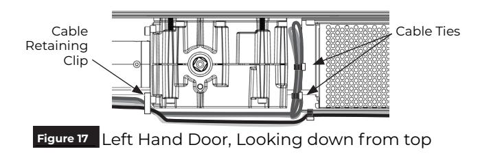
- 1. To prevent wire crimping, use the cable ties provided to neatly store loose wiring as shown. The power cabling to the connector board should be cable tied along the operator body. Any loose wire should be stored between the operator body and power supply. (Figure 17)
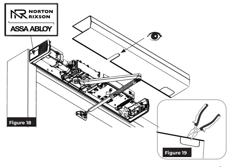
- 2. Align the cut-outs in the cover to pinion shafts. (Figure 18)
- 3. Optional : If the AC Bracket is installed, use pliers to remove the appropriate knockout located on the top of the cover. (Figure 19)
- 4. Slide the cover onto the unit using the end caps as a guide.
- 5. Snap the cover securely to the backplate.
- 6. Attach a label plate to each end cap by snapping it into place by hand with gentle pressure. (Figure 18)

WARNING: Make sure no wiring is loose or can be caught by cover when it is snapped into place.

This page intentionally left blank.
Technical Product Support: Monroe, NC 28112 USA Phone: 877.974.2255 ext: 2 Techsupport.NortonRixson@assaabloy.com NortonRixson.com