Norton Rixson 51 Shallow-Depth Floor Closer 3, 4 Offset Hinged, Single Acting – Handed Installation Instruction…_5100
Open the original PDF document
View PDF51 Floor Closer
3/4" Offset Hinged Single Acting, Handed Installation Instructions

ASSA ABLOY


How To Determine Hand of Door
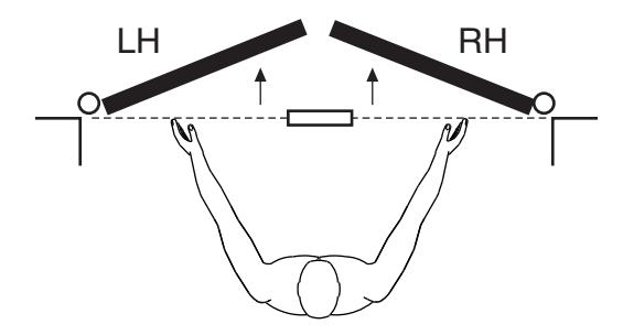
Face a door swinging open away from you. If it opens to the right, it is right hand. If it opens to the left, it is left hand.
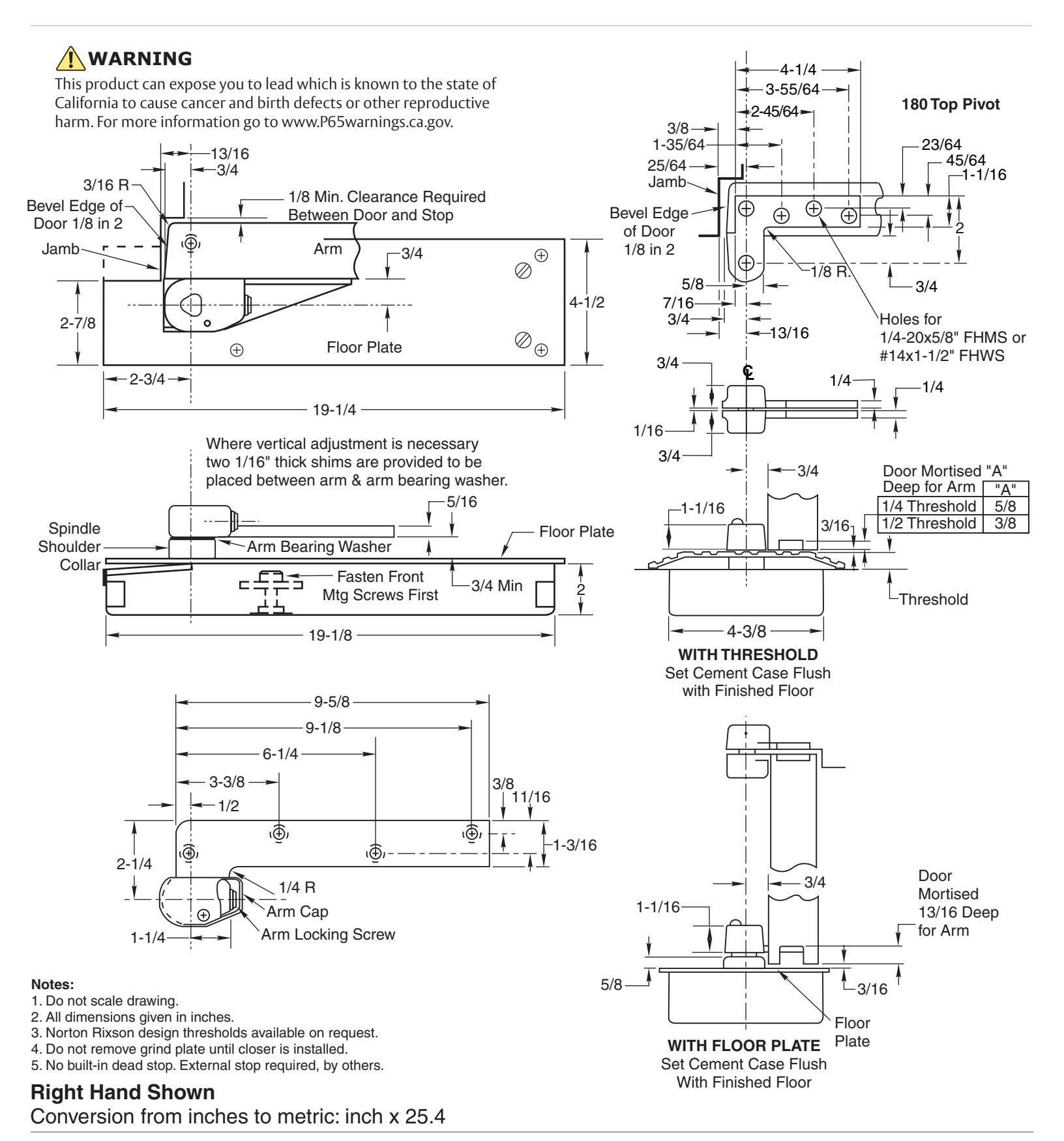
1. Locating Closer
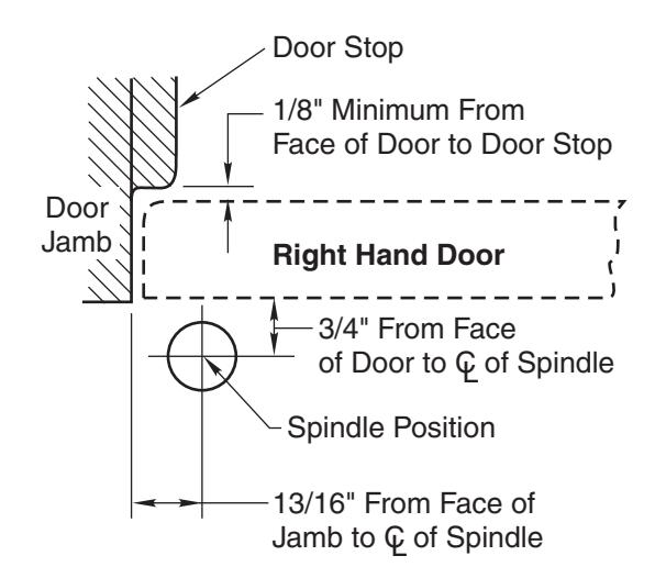
- A. Measure 13/16" out from door jamb.
- B. Allow 1/8" minimum clearance from door stop to door face. Measure door thickness. Add 3/4".
- C. Where lines meet determines center line of closer.
2. Install Cement Case in Floor
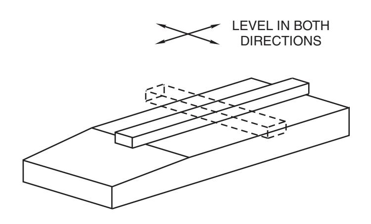
- A. Cement case is set flush with floor.
- B. Set cement case in floor and block in position.
- C. Case should be parallel with center line of door.
- D. CEMENT CASE MUST BE LEVEL. Place levels per illustration.
- E. Grout in cement case with closer. Cement should not get between closer and case.
51 Floor Closer

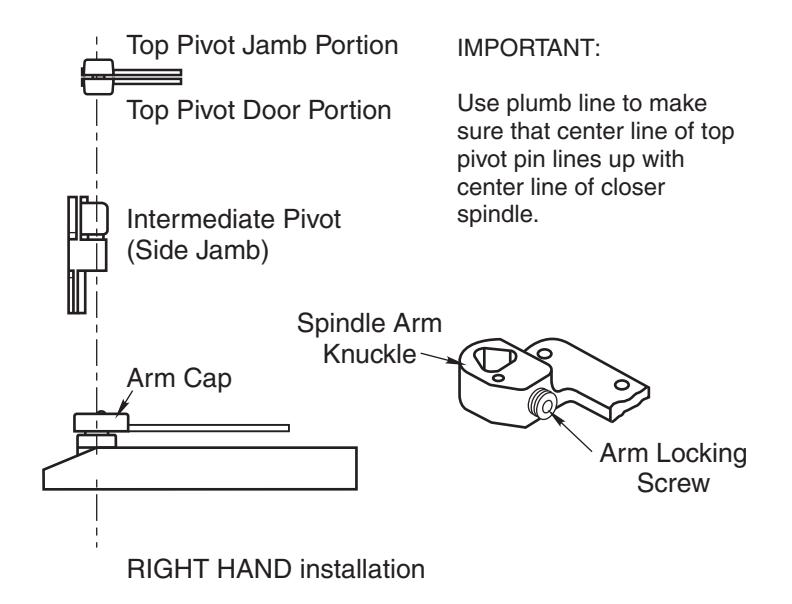
3. Install Top Pivot and Closer Arm
- A. Install top pivot in door per template.
- B. Install top pivot in frame per template.
- C. Center line of pivot should line up with center line of closer. Use plumb line as illustrated. If center lines don't line up, loosen hold down screws (4) and reposition closer. Tighten
- hold down screws closest to spindle first. Then tighten screws at cylinder end. Note: Closer must be lifted approximately 1/8" before repositioning.
- D. If side pivot is used, see template for intermediate pivot.
4. Hang Door
Right Hand Shown
4b 1 2 1 2 3 3
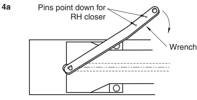
CAUTION: Closer is shipped with Closing Speed valve down. DO NOT FORCE VALVE DOWN.
- A. Using wrench, turn spindle until wrench is parallel with center line of closer. (Illustration 4a)
- B. Insert arm bearing washer over spindle then set door on closer spindle. Set door on closer spindle. DO NOT FORCE DOOR CLOSED WHILE "STROKE" VALVE IS TURNED DOWN.
- C. Push item 1 "top pivot pin" into place. Attach "cap" item 2. (Illustration 4b) CAP MUST BE TIGHTENED SECURELY.
- D. Open Stroke valve (counterclockwise) one turn.
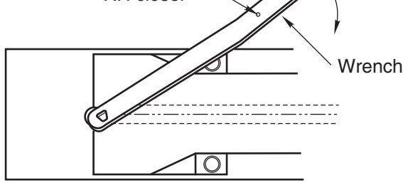
- E. If door drags at floor (or threshold, if used), raise door to desired clearance and insert one or more 1/16" shims. (Illustration 4c)
- F. While working door back and forth TIGHTEN ARM LOCKING SCREW SECURELY with wrench furnished.
- G. Put arm cap on closer spindle and secure TIGHTLY with cap screw furnished.
The ASSA ABLOY Group is the global leader in access solutions. Every day we help people feel safe, secure and experience a more open world.

Closer Adjustment
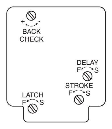
Closing speeds can be adjusted to suit local conditions and requirements. Label on closer face designates the purpose of each adjustment screw. Adjustments are for speed control.
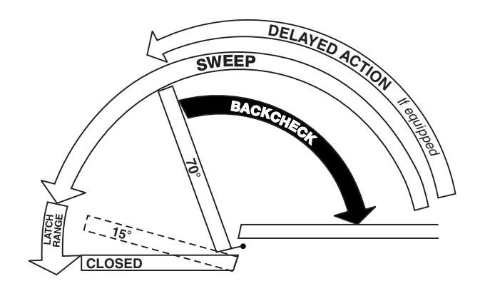
- A. The stroke valve allows adjustment from open to 15°.
- B. The latch valve allows adjustment from 15° to closed position.
- C. IMPORTANT: Back check valve option must be adjusted to vary resistance from light to firm at of door opening.
- D. The delay valve option allows closing speed adjustment from open position to 65°.
Repairs, parts replacement or internal adjustments must be done by a Norton Rixson authorized repair agency. Consult nortonrixson.com for an authorized repair agency in your area.