Norton Rixson 50 and 5020 Floor Closers Center Hung, Single or Double Acting Non-Handed Installation Instruction…_50
Open the original PDF document
View PDFCloser Adjustment PAGE 4
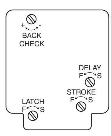
Closing speeds can be adjusted to suit local conditions and requirements. Label on closer face designates the purpose of each adjustment screw. Adjustments are for speed control.
- A. The stroke valve allows adjustment from open to 15°.
- B. The latch valve allows adjustment from 15° to closed position.
- C. IMPORTANT: Back check valve option must be adjusted to vary resistance from light to firm at 70° of door opening.
- D. The delay valve option allows closing speed adjustment from o en position to 65°. p
Repairs, parts replacement or internal adjustments must be done by a Rixson authorized repair agency. Consult www.rixson.com for an authorized repair agency in your area.

Copyright © 2005, 2009, 2024, ASSA ABLOY Accessories and Door Controls Group, Inc. All rights reserved. Reproduction in whole or in part without the express written permission of ASSA ABLOY Accessories and Door Controls Group, Inc. is prohibited.
Rixson Specialty Door Controls www.rixson.com 866-474-9766 Technical Department Rixson Specialty Door Controls www.rixson.com 866-474-9766 Technical Department
RIXSON ®
ASSA ABLOY
Installation Instructions
50 Rev 3 (0 5-24)
50 Floor Closer Center Hung Single or Double Acting
Non-Handed
Conversion from inches to metric: inch x 25.4. 7. External stop by others required. ASSA ABLOY 8. All dimensions given in inches.
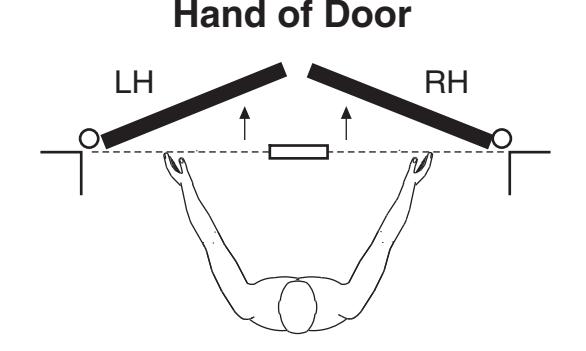
Face a door swinging open away from you. If it opens to the right, it is right hand. If it opens to the left, it is left hand.
Installation Instructions
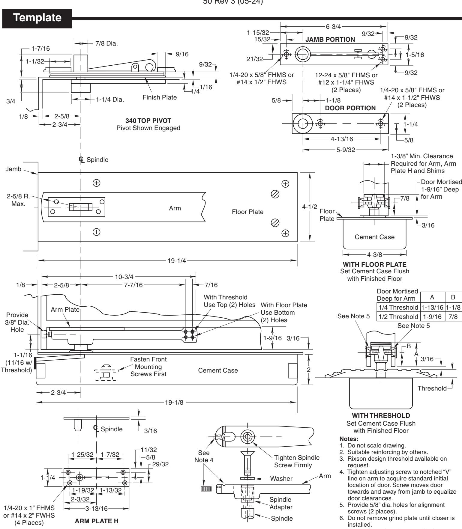
1. Locating Closer
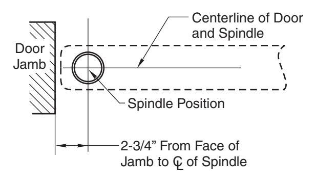
A. Measure 2-3/4" out from door jamb on centerline of door. This is the location of the spindle center.
2. Install Cement Case in Floor
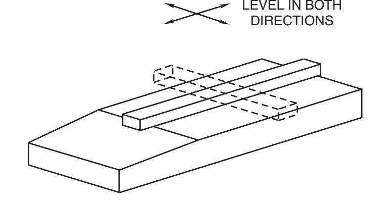
- A. Cement case is set flush with finished floor.
- B. Set cement case with closer in floor and block in position.
- C. Case should be parallel with center line of door.
- D. CEMENT CASE SHOULD BE LEVEL. Place levels per Illustration.
- E. Grout in cement case with closer. Cement should not get between closer and case.
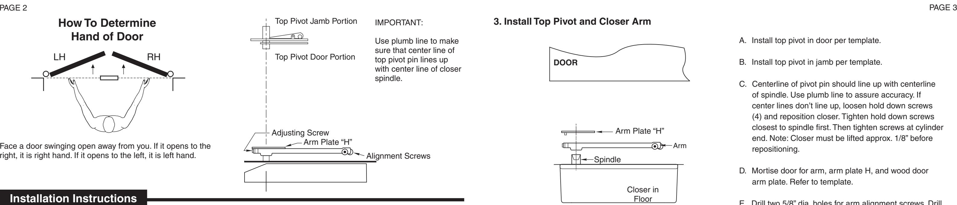
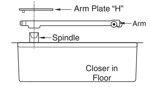
3. Install Top Pivot and Closer Arm
4. Hang Door
- A. Install top pivot in door per template.
- B. Install top pivot in jamb per template.
- C. Centerline of pivot pin should line up with centerline of spindle. Use plumb line to assure accuracy. If center lines don't line up, loosen hold down screws (4) and reposition closer. Tighten hold down screws closest to spindle first. Then tighten screws at cylinder end. Note: Closer must be lifted approx. 1/8" before repositioning.
- D. Mortise door for arm, arm plate H, and wood door arm plate. Refer to template.
- E. Drill two 5/8" dia. holes for arm alignment screws. Drill 3/8" hole at heel edge of door for adjusting screw.
- F. Attach arm alignment screws and washers to hold arm in place. Install arm, arm plate H, and shims if required.
CAUTION: Closer is shipped with "valve" screws down. DO NOT FORCE VALVE DOWN.
- A. Close both valve screws. NEVER FORCE VALVE SCREW DOWN AS THIS WILL DAMAGE TIP SEATING.
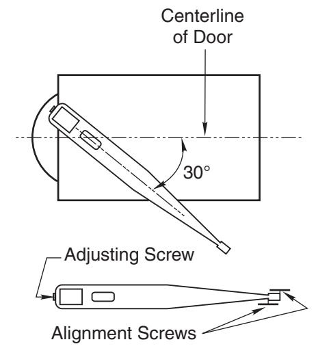
- B. With arm on spindle, turn spindle until arm is in 30° open position (see illustration).
- C. Set door on spindle. DO NOT ATTEMPT TO CLOSE DOOR.
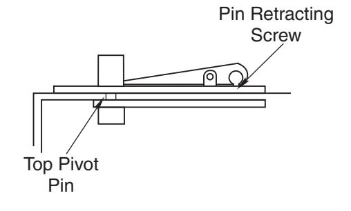
- D. Align two portions of top pivot and turn pin retracting screw clockwise to engage top pivot pin.
- E. Open door to 60° or more and turn valve screws counterclockwise. Door will then close.
- F. If necessary, turn adjusting screw at bottom of heel edge of door to equalize side jamb clearances.
- G. Adjust center door in doorway. arm alignment screws equally from each side to
Rixson Specialty Door Controls Rixson Specialty Door Controls