Norton Rixson 4500 Series Power Operator, Model 4540, Push & Pull Mounting Installation Instructions_80-9345-0001-020
Open the original PDF document
View PDF4500 Series Power Operator Model 4540, Push & Pull Mounting
RIXSON
ASSA ABLOY
Installation Instructions

This product can expose you to lead which is known to the state of California to cause cancer and birth defects or other reproductive harm.
For more information go to: www.P65warnings.ca.gov.
Pour la version française voir NortonRixson.com. READ AND FOLLOW ALL INSTRUCTIONS. SAVE THESE INSTRUCTIONS.
available for purchase separately. (P/N 4501PCK)
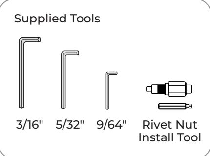
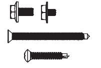
Supplied Hardware
| Mounting Hardware | Door or Frame | Drill | |
|---|---|---|---|
|
Soffit Plate or Shoe:
1/4-20 x 2-1/4" OR 1/4-20 x 3/4" Flat Head Machine Screw (Qty: 5) |
Metal | N/A | |
|
Soffit Plate or Shoe:
1/4-14 x 1-1/2" OR 1/4-14 x 1-1/2" Self Drilling Screw (Qty: 5) |
Wood | 7/64" (2.78mm) | |
|
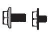
Backplate to Door:
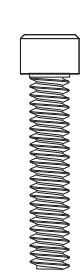
1/4-20 x 1" Button Head Machine Screw (Qty: 6) |
All | N/A | |
|
Backplate to Door:
1/4-20 Sleeve Nut (Qty: 4) |
Wood or
Metal (recommended) |
3/8" (9.50mm) drill | |
|
Backplate to Door:
1/4-20 Rivet Nut (Qty: 10) |
Metal Frames
Metal Doors (optional) |
9/32" (7.00mm) thru | |
|
Operator to Bracket:
1/4-20 x 1-1/4" with Loctight (Qty: 2) |
All | N/A | |
|
Arm to Operator:
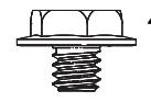
1/4-20 x 1/2" Hex Head Flanged Machine Screw (Qty: 1) |
All | N/A | |
|
Locking Bracket to Operator:
8/32 x 5/16" Socket head Machine Screw (Qty: 2) |
All | N/A | |
| Arm to Soffit Plate (Pull) (Qty: 1) | All | N/A | |
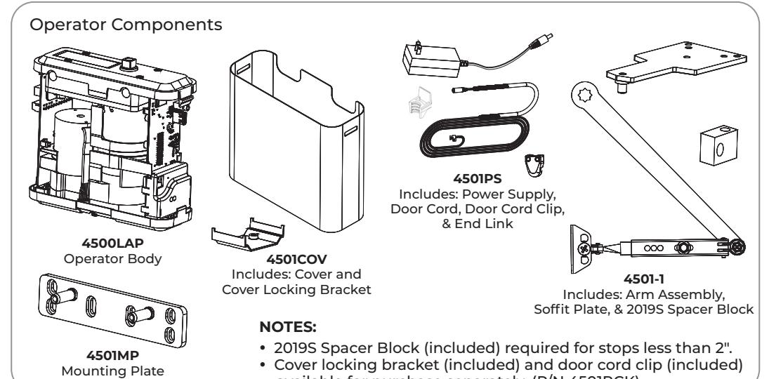
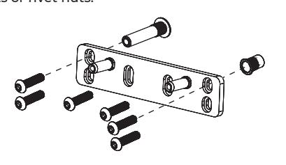
Operator Mounting Plate: (included). Used with Push Side applications only. Mounted with sleeve nuts or rivet nuts.
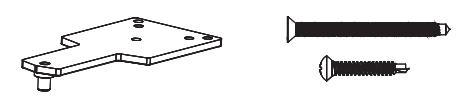
Soffit Plate : Used in Push Side applications only.
Brackets: Soffit Reinforcement: (for some installs)
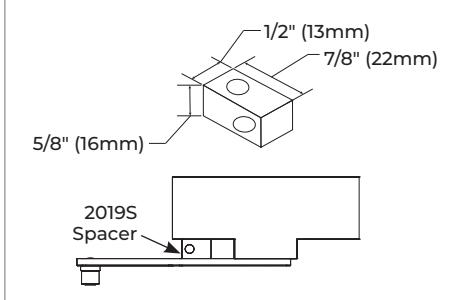
Standard - 2019S Spacer Block : For use where a narrow frame soffit does not provide adequate support for the soffit plate. For use on a frame with either 1/2" (13mm) or 5/8 (16mm) high frame stops.
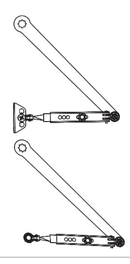
Arm:
Pull Configuration: Long with Shoe
Push Configuration: Short, shoe removed
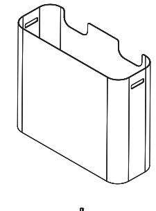
Operator Cover
Cover Locking Bracket
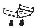
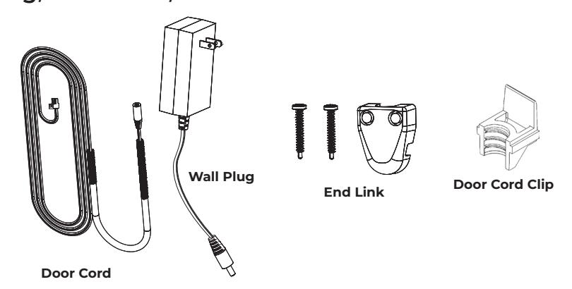
Covers: Wall Plug, Door Cord, and End Link:

Contents
| Supplied Hardware | 2 |
|---|---|
| Certifications and Standards | 3 |
| Technical Data | 3 |
| Product Safety Warnings . | 3 |
| Before You Begin . | 4 |
| Installation . | 4 |
Certifications and Standards
- y ETL Certified: This product conforms to ANSI/UL standard 325 for automatic closing doors.
- y ANSI A156.19: This product is designed to conform to this specification.
- y Americans with Disabilities Act (A.D.A.): This product can be installed and adjusted to conform with A.D.A. regulations.
- y ANSI A117.1: This product permits door assemblies to conform to the requirements of this specification.
Technical Data
| Input power: | 120VAC, 60Hz 1.3A Max. | NOTE: |
|---|---|---|
| Power supply: |
24 V DC, max. 2.0 Amp.; Class 2, 200mA constant for Acc.;
250mA Relay Output |
|
| Door width: | 36 - 48" (91-122 cm) | codes. |
| Door weight: | 90-200 lb. (41-91 kg) | |
| Push max angle: | 90° | |
| Pull max angle: | 90° | |
|
Hold open time:
5-30 seconds (A.D.A. 5 seconds min.) after activation. |
||
y Permanent wiring is to be employed as required by local codes.
Product Safety Warnings
WARNING: To reduce risk of injury to person, use this operator only with Pedestrian Swing doors. FOR INDOOR USE ONLY
- 1. READ AND FOLLOW ALL INSTRUCTIONS.
- 2. Install only on a properly operating and balanced door. A door that is operating improperly could cause severe injury. Have qualified service personnel make repairs to any hardware before installing the operator.
- 3. Remove, or make inoperative, all locks (unless mechanically and/or electrically interlocked to the power unit) that are connected to the door before installing the operator.
- 4. Do not connect the door operator to the source power until instructed to do so.
- 5. Never let children operate or play with door controls. Keep remote control (when provided) away from children.
- 6. Personnel should keep away from a moving door in motion.
- 7. Test door's safety features at least once a month. After adjusting either force or limit of travel, retest door operator's safety features. Failure to adjust operator properly may cause severe injury or death.
- 8. KEEP DOOR PROPERLY OPERATING. See Door Manufacturer's Owner's Manual. An improperly operating door could cause severe injury or death. Have a trained door systems technician make repairs.
- 9. SAVE THESE INSTRUCTIONS.
Before You Begin
- y Thickness recommended for reinforcements in hollow metal doors and frames is charted.
- y This template information based upon use of 5" maximum width butt hinges.
- y Before beginning the installation, verify that the door frame is properly reinforced and is well anchored in the wall.
- y This product will not operate correctly on balanced doors or doors with swing clear hinges.
-
y If the door is an aluminum storefront door, EXAMINE top rail. Before drilling the mounting holes, ENSURE the following:
- ‒ Do not drill into the top rail web.
- ‒ Do not drill into the rail-to-stile tie rod(s).
- ‒ Do not drill into the rail-to-stile junction.
- y Concealed electrical conduit and concealed switch or sensor wires should be tied to the frame before proceeding.
| Hollow Metal Door Frame Reinforcing | |||||
|---|---|---|---|---|---|
| Reinforcing | |||||
| Frame Material | Recommended | Min. Required | |||
| 12 Ga. | 12 Ga. | 18 Ga. | |||
| .1046 | .1046 | .0478 | |||
| (2.66) | (2.66) | (1.21) | |||
| 14 Ga. | 10 Ga. | 12 Ga. | |||
| .0747 | .1343 | .1046 | |||
| (1.90) | (3.41) | (2.66) | |||
| 16 Ga. | 10 Ga. | 12 Ga. | |||
| .0598 | .1343 | .1046 | |||
| (1.52) | (3.41) | (2.66) | |||
| 18 Ga. | 8 Ga. | 10 Ga. | |||
| .0478 | .1644 | .1343 | |||
| (1.21) | (4.18) | (3.41) | |||
Installation
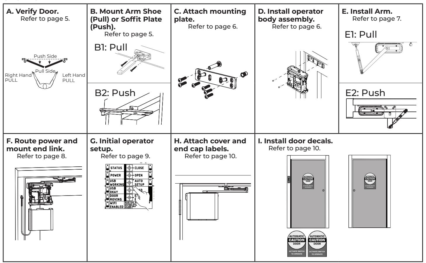
Overview

Installation (cont.)
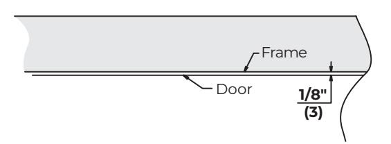
A. Verify frame and door installation.
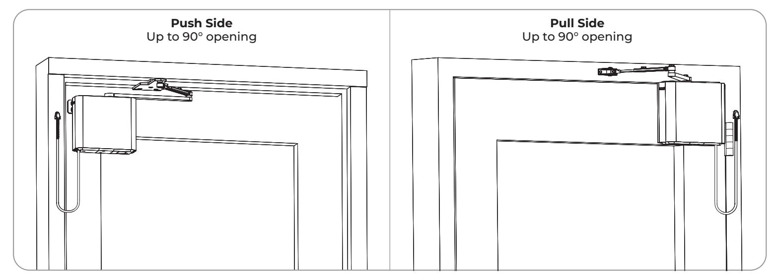
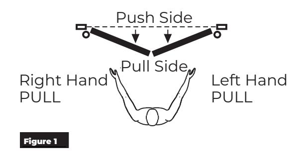
- 1. Determine if right hand or left hand installation. (Figure 1)
- 2. Determine if install is Push or Pull.
- 3. Verify the Frame is square
- 4. Verify the gaps between door and frame are consistent. Gap should be 1/8" at jambs and header (+/- 1/16" for hollow metal doors)
- 5. Refer to the Pull or Push dimensions below.
B. Mount Arm Shoe (Pull Applications) or Soffit Plate (Push Applications).
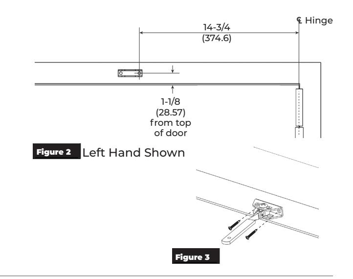
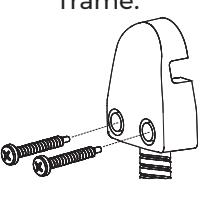
B1: Arm Shoe for Pull Applications
- 1. Using the template, mark the location of the first hole. (Figure 2)
-
2. Drill the first mounting hole. Install Rivet nut for metal frames.
- ‒ For metal frames : Use 25/64" drill, provided rivet nut tool, and 1/4-20 rivet nut, and 1/4-20 screws
- ‒ For wood frames : Use 7/64" drill and 1/4" self-tapping screws
- 3. Install first screw and attach Arm Shoe to the frame. Do not tighten fully.
- 4. Level the shoe arm, mark and drill the second mounting hole.
- 5. Install the second screw and secure with the proper hardware. Tighten both screws. (Figure 3)
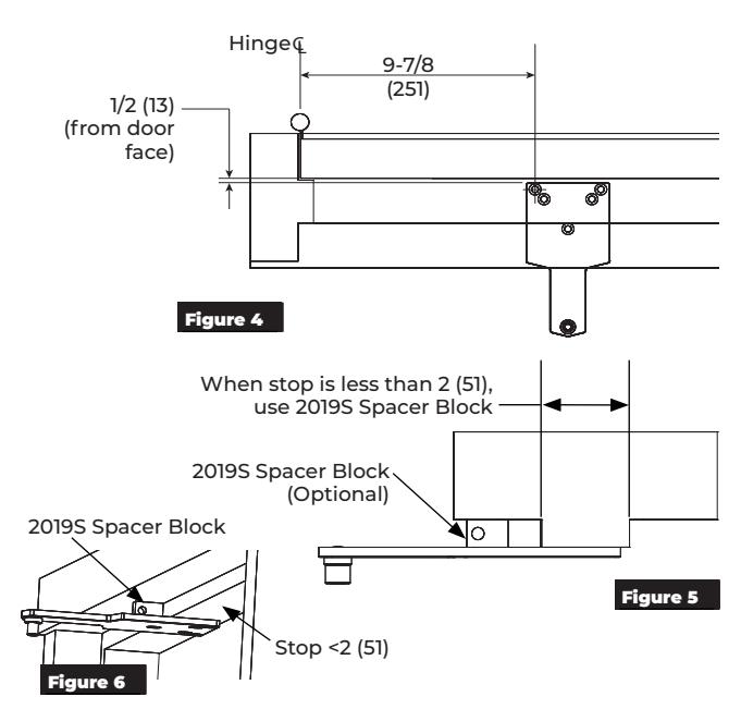
B2: Soffit Plate for Push Applications
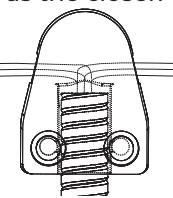
- 1. Using the template, mark location of the first hole. (Figure 4)
-
2. Drill the first mounting hole. Install Rivet nut for metal frames.
- ‒ For metal frames :
Use 25/64" drill, provided rivet nut tool, and 1/4-20 rivet nut, and 1/4-20 screws
‒ For wood frames :
Use 7/64" drill and 1/4" self-tapping screws
- 3. Install first screw and attach the soffit plate. Do not tighten fully.
- 4. Level the soffit plate to door. Mark and drill the three (3) or four (4) additional holes.
NOTE: If the stop is less than 2", use the 2019S Spacer Block aligned with the center screw of the soffit plate. If the center screw aligns with the transition from stop to rabbet, the Spacer Block is optional. (Figure 5 & Figure 6)
5. Install remaining screws and secure with proper hardware. Tighten all screws.
5

Installation (cont.)
C. Attach mounting plate.
NOTE: PUSH & PULL templates are not the same. Confirm the correct template is being used before performing this step.
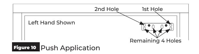
- 1. Measure and mark the first mounting hole according to template. (Figure 7 & Figure 8)
- 2. Drill the first mounting hole for the Sleeve Nuts (recommended) or drill and install Rivet nut (alternate for metal frame).
For All Doors: Use the 3/8" drill, the sleeve nuts, and 1/4-20 screws. For doors less than 1-3/4" thick, shorten the sleeve nut body.
For Metal Doors (alternate installation): Use the 25/64" drill, the provided rivet nut tool, the 1/4-20 steel rivet nuts, and 1/4-20 screws
- 3. Install first screw and attach mounting plate. Do not tighten fully.
- 4. Level the mounting plate on the door. Using the mounting plate as a guide, mark and drill second hole.
- 5. Insert the second screw and attach mounting plate. Do not tighten fully. (Figure 9 & Figure 10)
- 6. Using mounting plate as a guide, drill and install the two (2) outer sleeve nuts or Rivet Nuts.
NOTE: The two (2) center screws are optional.
7. Secure and tighten the remaining screws.
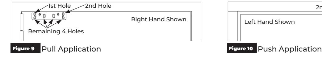
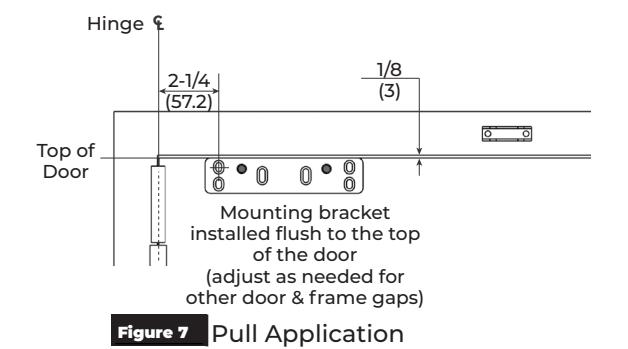
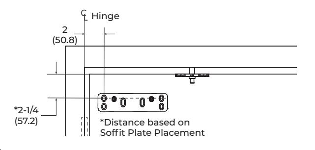
Figure 8 Push Application
D. Install operator body.
Using two (2) 1/4-20 x 1-1/4" screws, install the operator body to mounting plate. (Figure 11)
NOTES:
- y Alternate tightening screws until both are tight.
- y Operator body is in proper orientation when the I/O Board is toward the hinge. (Figure 11)
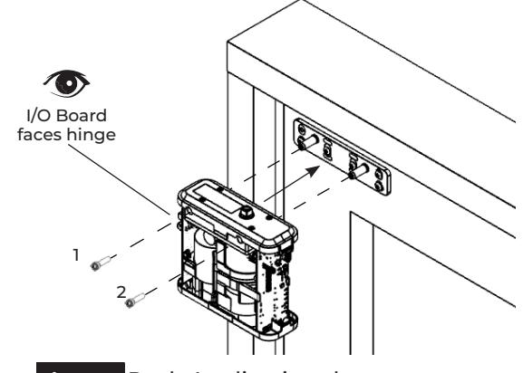
Figure 11 Push Application shown

Installation (cont.)
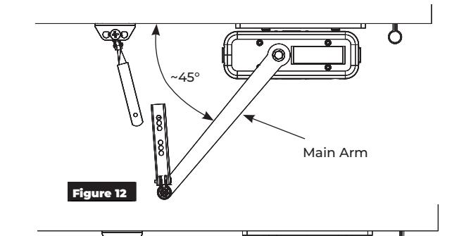
E. Install arm.
NOTE: Once the arm is installed, any movement of the door will cause the operator LEDs to illuminate.
E1. Pull Side Application
- 1. Install the main arm on the pinion at approximately 45°. (Figure 12)
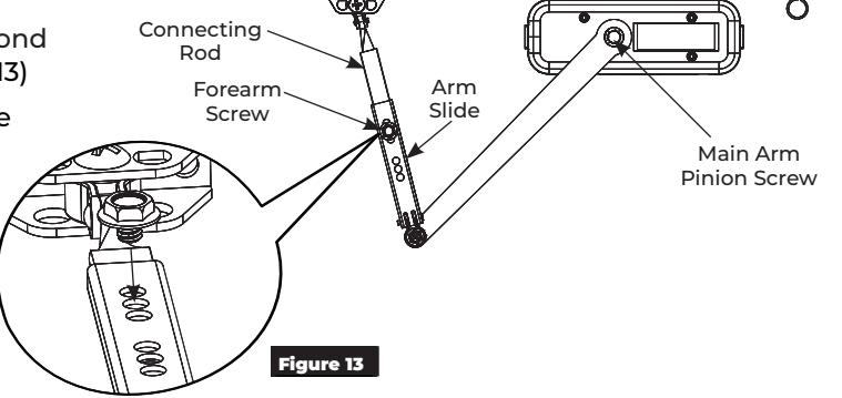
- 2. Install the main arm pinion screw. (Figure 13)
- 3. Slide the connecting rod into the arm slide. (Figure 13)
4. Install and tighten the forearm screw in the second hole from the end of the arm as shown. (Figure 13)
NOTE: If the arm needs to be adjusted to achieve full 90° operation of the door, the screw can be moved one hole in either direction.
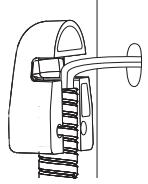
E2. Push Side Application
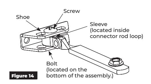
- 1. Remove the shoe from the connector rod assembly. (The shoe is used for pull mounting and will not be needed for this application.) Discard the shoe, sleeve, screw, and bolt. (Figure 14)
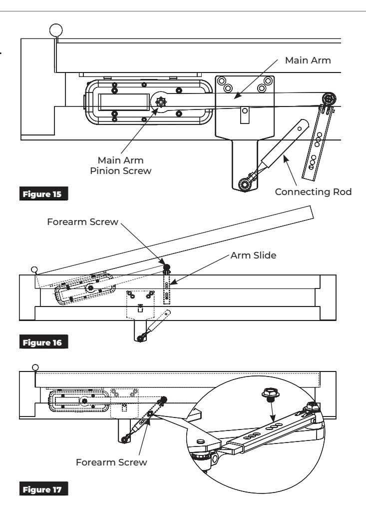
- 2. Mount the connecting rod onto the soffit plate using the 10-32 hex head screw provided. (Figure 15)
- 3. Install the Main arm on the pinion parallel to the door as shown. (Figure 15)
- 4. Install the Main Arm Pinion Screw. (Figure 15)
- 5. Open the door approximately 30° and slide the connecting rod into the arm slide. (Figure 16)
6. Close the door. Install and tighten the forearm screw in the second hole from the end of the arm as shown. (Figure 17)
NOTE: If the arm needs to be adjusted to achieve full 90° operation of the door, the screw can be moved one hole in either direction.

Installation (cont.)
F. Route power and mount end link.
- 1. Route the power supply transformer wiring to a 110VAC outlet. DO NOT plug the transformer in at this time. (Figure 20)
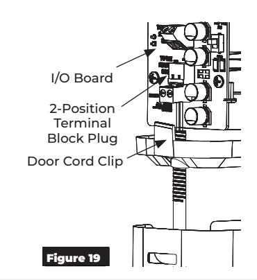
- 2. Secure the door cord by installing the door cord clip into the end cap of the operator. (Figure 20)
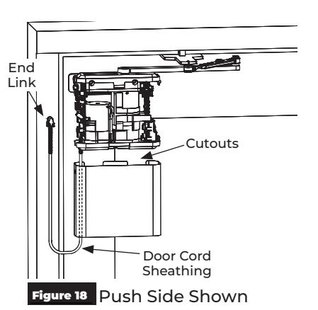
- 3. Secure the opposite end of the door cord to the end link. The door cord sheathing will fit snuggly in the groves of the end link. (Figure 20)
- 4. Secure the end link to the frame or wall near the closer using the two (2) screws provided. (Figure 20) Figure 18 Push Side Shown
Wiring routed through gaps on either side of the end link when power is located on the same side as the closer.
Wiring routed through a hole drilled through the wall or frame near the operator.
Secure the end link to the wall or frame.

Installation (cont.)
G. Initial Operator Setup.
NOTE: Setup can alternatively performed via Wifi interface. Refer to the Programming Instructions
Set the closed position :
- 1. Fully close the door.
-
2. Press and release the CLOSE button on the control board.
- ‒ The yellow CLOSE LED will change from flashing to solid. (Figure 21)
NOTE: When the door is in the closed position, the yellow LED will illuminate solid.
Set the open position :
-
1. Manually open door to its fully open position (90° or less).
- ‒ The green OPEN LED will begin flashing.
NOTE: If there is a wall or door stop at the fully open position, hold the door slightly away from wall or stop.
-
2. With the door in the open position, press and release the OPEN button on the control board.
- ‒ The flashing green OPEN LED will turn solid once the position has been set. (Figure 22)
NOTE: When the door is in the fully open position, the green LED will illuminate solid.
Run Auto Setup:
- 1. Manually close the door. Once fully closed, confirm there are no obstructions or latching hardware that could prevent the door from opening.
-
2. Press and release the AUTO SETUP button on the control board.
- ‒ The door will open and close in small increments three (3) times.
Allow door to open and close without interference. (Figure 23)
The blue Auto Setup LED will turn off once Auto Setup is complete
Verify Setup:
Auto Setup will automatically configure closing speeds and maximum forces to comply with ANSI/BHMA A156.19 on most doors. If ANSI/BHMI compliance is required for the installation, verify door speeds and forces.
Setup is now completed with default settings.

If settings require adjustment, continue with the Programming Manual to set up and adjust operator. Once programming and adjustments have been completed, continue to page 10.

Speed/Force and Timing/Location settings must be adjusted to meet ANSI BHMA A156.19 (American National Standard for Power Assist and Low Energy Power Operated Doors) requirements for opening and closing based on door weight and width.
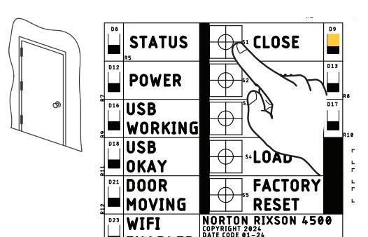
Figure 21
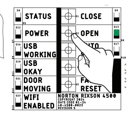
Figure 22
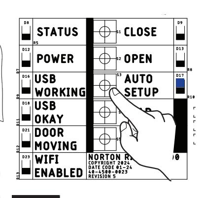
Figure 23
Opening
Closing

Installation (cont.)
H. Attach cover and end cap labels.
NOTE: Attach cover after initial programming and full installation has been completed.
- 1. Slide the metal slip-on cover over the operator body from the bottom up. (Figure 24)
- 2. Snap metal cover over the plastic tabs near the top of the closer assembly. (Figure 25)
- 3. Place Cover Locking Bracket on the bottom of the assembly and attach with the two (2) 8-32 x 5/16" screws provided. (Figure 25)
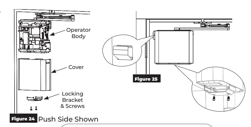

WARNING: Make sure no wiring is loose or can be caught by cover before snapping it into place
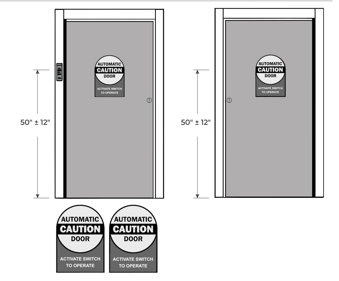
I. Install door decals.
Technical Product Support: Monroe, NC 28112 USA Phone: 877.974.2255 ext: 2 Techsupport.NortonRixson@assaabloy.com NortonRixson.com