Norton Rixson 375 Pivot Set, Center Hung Installation Instructions_IS-375
Open the original PDF document
View PDF375 Pivot Set
Center Hung Installation Instructions


WARNING
This product can expose you to lead which is known to the state of California to cause cancer and birth defects or other reproductive harm. For more information go to www.P65warnings.ca.gov.
Ce produit peut vous exposer au plomb qui, dans l'état de la Californie, est reconnu pour causer le cancer, des anomalies congénitales ou d'autres problèmes de reproduction. Pour plus d'informations, visitez: www.P65warnings.ca.gov.
IMPORTANT: It is responsibility of door and frame manufacturers to check hardware schedule and prepare doors and frames. The following instructions cover field prep.
1. Prepare door and opening.
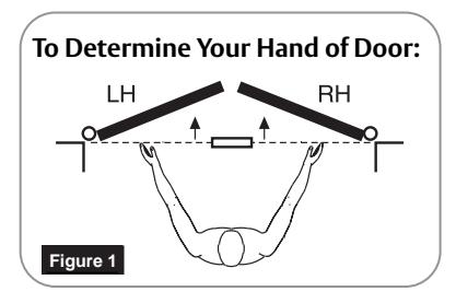
- 1. Determine hand of door for proper placement of pivot set. (Figure 1)
- 2. Confirm pivot side of door frame is both plumb and straight with respect to frame rabbet and frame face surfaces.
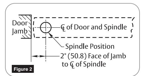
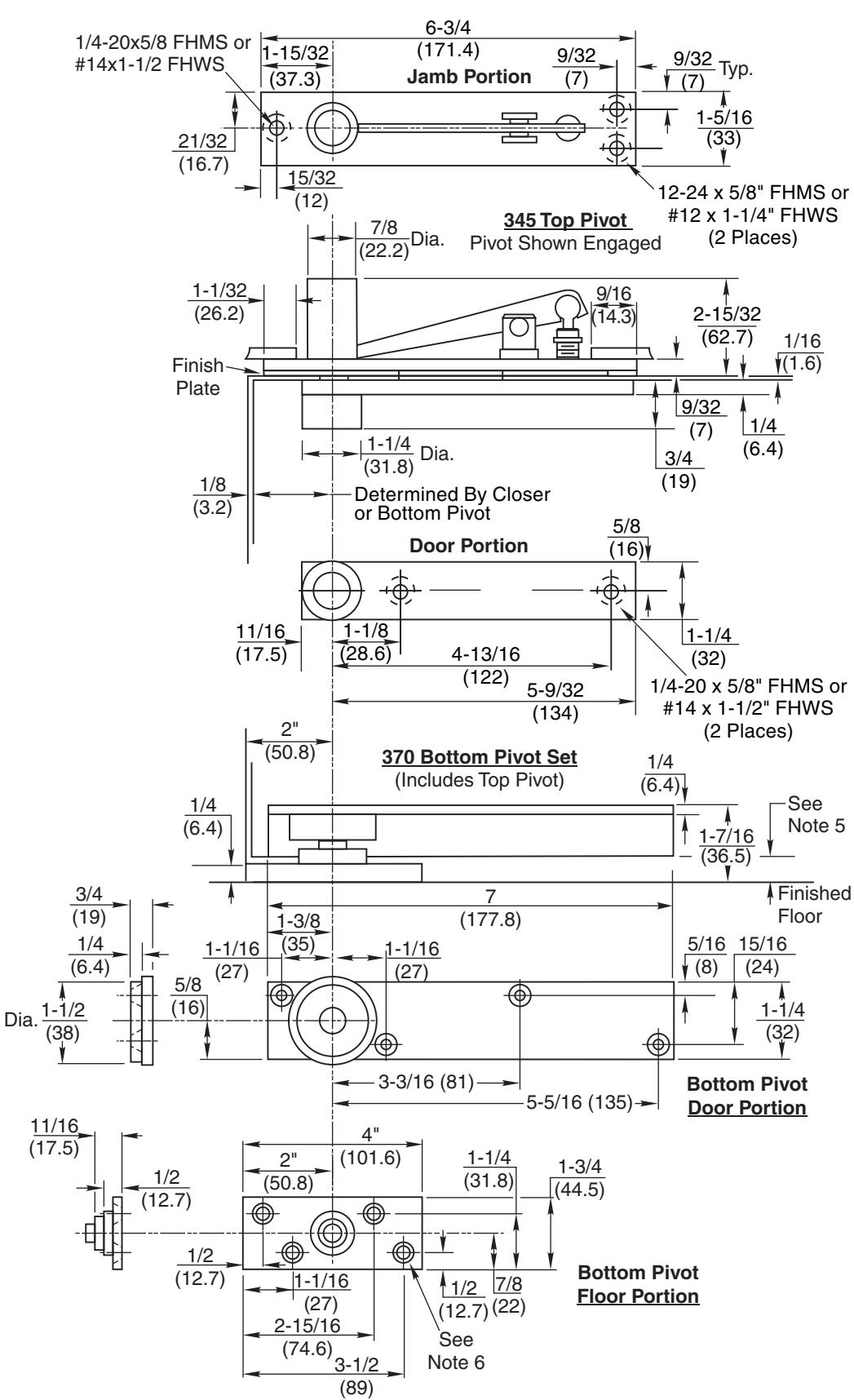
- 3. Mark frame header and door for top pivot. (Figure 2) Using template PS30625, note the requirement for door radius on heel edge of door.
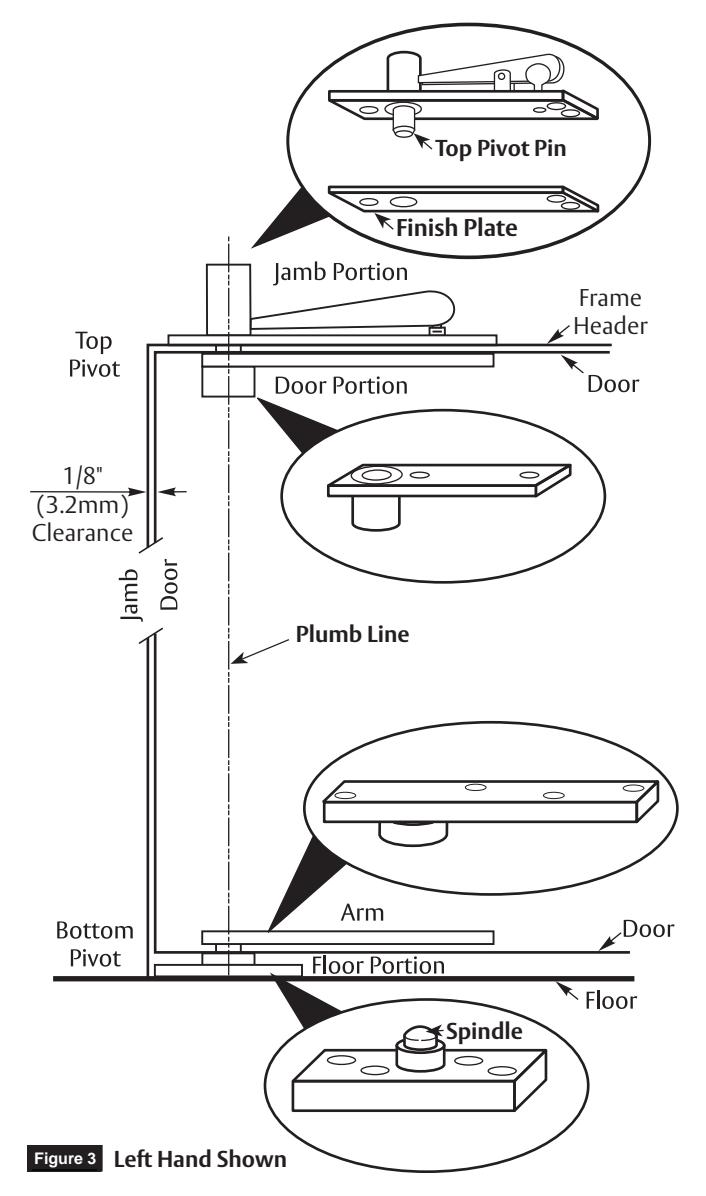
- 4. Install jamb portion and finish plate of top pivot into frame header using two (2) 12-24 x 5/8" FHMS or #12 x 1-1/4" FHWS and one (1) 1/4-20 x 5/8" FHMS or #14 x 1-1/2" FHWS. (Figure 3) Refer to template PS30625.
- 5. Using Norton Rixson alignment tool 2608, secure plumb line to jamb portion top pivot pin. (Figure 3)
- 6. Using plumb line, locate bottom pivot floor portion spindle centerline. With bottom pivot floor portion as template, mark location of mounting holes. (Figure 3)
NOTE: Confirm floor portion placement using template PS30625 with respect to frame rabbet and frame face. If not accurate, frame may not meet straight and plumb requirements of step 2 above.
7. Radius heel edge of door for 1/8" (3.2mm) minimum clearance through entire opening per template PS30625.
NOTE: Maximum radius 1-7/8" (47.6mm) for 1-3/4" to 2-1/2" (44.5mm to 63.5mm) doors.
- 8. Mortise and prepare holes in top of door for top pivot door portion.
- 9. Mortise and prepare holes in bottom of door for bottom pivot door portion.
NOTE: Mortise depth in bottom of door must be coordinated with required clearance between door bottom and floor. 5/16" (7.9mm) Min. Clearance = 1-1/8" (28.6mm) Mortise depth 11/16" (17.5mm) Max. Clearance = 3/4" (19mm) Mortise depth

2. Install pivot set.
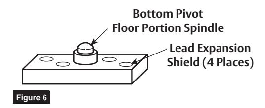
1. Install floor portion of bottom pivot securely to floor using four (4) 1/4-20 x 5/8" FHMS or #14 x 1-1/2" FHWS and provided lead expansion shields. (Figure 6)

NOTES:
Care must be taken that bottom pivot is level.
Center of top pivot pin must align with bottom pivot floor portion spindle. If door and frame is pre-prepped, follow steps 5 and 6 of "Prepare door and opening" to confirm this alignment requirement.
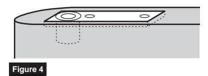
- 2. Install door portion of top pivot in door using two (2) 1/4-20 x 5/8" FHMS or #14 x 1-1/2" FHWS. (Figure 4) Refer to template PS30625.
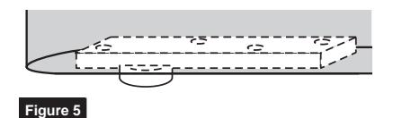
- 3. Install door arm in bottom of door using four (4) 1/4-20 x 5/8" FHMS or #14 x 1-1/2" FHWS. (Figure 5)
3. Hang door.

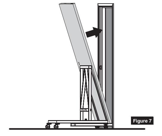
Caution: Know weight of door before attempting to install. Determine proper equipment needed to prevent door from falling. (Figure 7)
- 1. Set door on floor pivot spindle and tilt top of door pivot portion into top jamb portion. (Figure 7)
- 2. Engage top pivot pin by turning pin retracting screw clockwise. (Figure 8)
To remove door:

Caution: Know weight of door before attempting removal from frame. Determine proper equipment needed to prevent door from falling. (Figure 7)
- 1. Open door enough to gain access to pin retracting screw.
- 2. Secure door so it will not fall from opening during following steps.
- 3. Turn top pivot pin retracting screw counter clockwise to disengage top pivot pin.
- 4. With door securely held, carefully allow door to rotate on bottom pivot toward closed position.
- 5. Leaning door at header to allow top of door to clear frame rabbet, lift door to clear bottom pivot spindle.

Figure 8
Technical Product Support: Monroe, NC 28112 USA Phone: 877.974.2255 ext: 2 Techsupport.NortonRixson@assaabloy.com NortonRixson.com
NOTES:
- IMPORTANT: It is responsibility of door and frame manufacturers to check hardware schedule and prepare doors and frames.
-
12-24 x 5/8" FHMS or 2. Suitable reinforcing by others.
- 3. For 1-3/4" to 2-1/2" (44.5 to 63.5) doors radius on heel edge of door 1-7/8" (47.6) max.
- 4. Minimum Pivot Point is 2" (50.8).
- 5. Coordinate door mortise depth with required clearance: 5/16" (7.9) Min Clearance = 1-1/8" (28.6) Mortised Depth 11/16" (17.5) Max Clearance = 3/4" (19) Mortised Depth
- 6. Use lead expansion shields furnished.
- 7. Dimensions given in inches (mm).