Norton Rixson 327 Floor Closer, Door Hung on Ball or Butt Hinges, Single Acting, Handed Installation Instruction…_32700T
Open the original PDF document
View PDF327 Floor Closer
Door Hung on Ball or Butt Hinges Single Acting - Handed Installation Instructions


Norton Rixson
This product can expose you to lead which is known to the state of California to cause cancer and birth defects or other reproductive
harm. For more information go to www.P65warnings.ca.gov. To clear arm cut flange off push side of door below rail. Length of cut: 12-1/2" → from heel of door. -11-3/8 Floor Plate Rail must -2-1/4→ extend to hinge edge Arm Locking Screw 5-7/8 Cement Case 6-1/8 Floor Plate of door. Closer Spindle Jamb
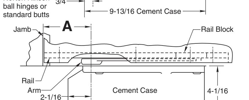
11-1/8
DIMENSION "A" SHOWN IN THE TABLES ARE FOR 1-3/4" THICK DOORS ONLY-CONTACT THE FACTORY FOR DOORS OTHER THAN 1-3/4"
IMPORTANT
Select Correct Dim. "A" From Tables Shown For Setting Floor Closer
For 90° Door Opening on 1-3/4" Doors Door Stops and/or Holds Open at 90°
| Boor otopo anaror morao opon at oo | |||
|---|---|---|---|
| Type of Hinge | Dim "A" | ||
| M19 side jamb pivots | 4-7/16 | ||
| M-3 side jamb pivots | 3-7/8 | ||
| 4-1/2" x 4-1/2" Butt Hinge | 3-3/4 | ||
| 4" x 4" Butt Hinge | 3-1/2 | ||
Optional Heavy Duty Door Stop Required
For 95° Door Opening on 1-3/4" Doors Door Stops and/or Holds Open at 95°
| Type of Hinge | Dim "A" | |
| M19 side jamb pivots | 3-15/16 | |
| M-3 side jamb pivots | 3-3/8 | |
| 4-1/2" x 4-1/2" Butt Hinge | 3-1/4 | |
| 4" x 4" Butt Hinge | 2-15/16 | |
Right Hand Shown
- 1. Dimensions given in inches. Conversion from inches to metric: inch x 25.4.
- 2. Norton Rixson designed threshold available on request.
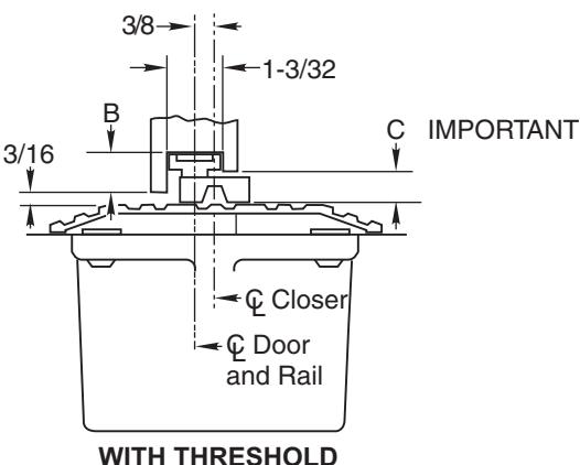
- 3. When threshold is used, door closer furnished must have a long spindle.
| 1/4 Threshold | B=1-1/16 | C=7/8 |
|---|---|---|
| 1/2 Threshold | B=13/16 | C=5/8 |
Set Cement Case Flush with Finished Floor
Set Cement Case 1/8" Below Surface of Finished Floor


How To Determine Hand of Door
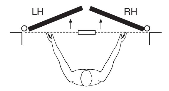
Face a door swinging open away from you. If it opens to the right, it is right hand. If it opens to the left, it is left hand.
IMPORTANT:
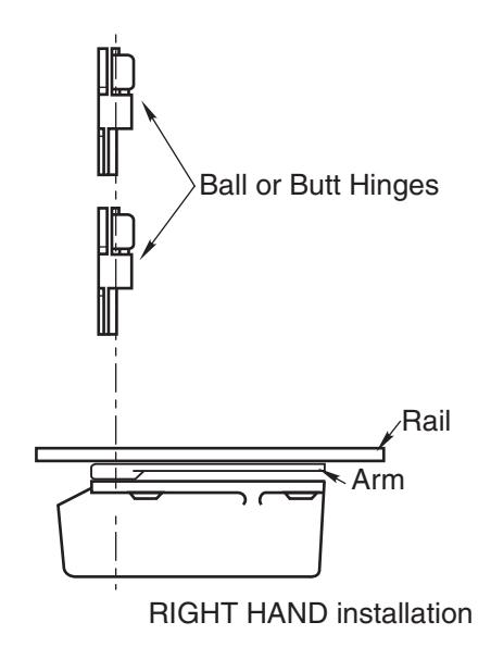
Use plumb line to be sure that hinge pins are in perfect alignment.
1. Locating Closer
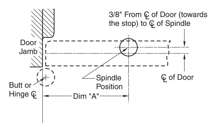
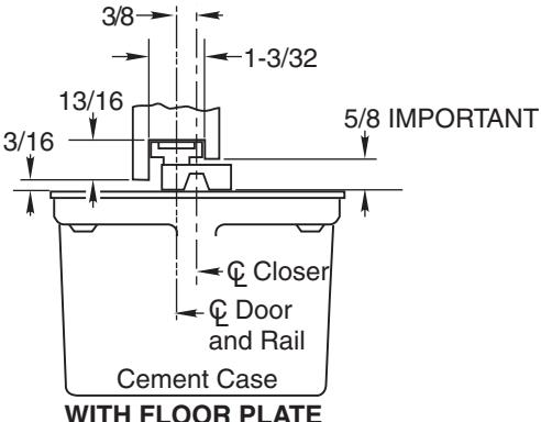
- A. Measure from the door stop 1/2 the thickness of door to determine centerline of door.
- B. To determine centerline of closer measure back towards the stop side 3/8" from centerline of door.
- C. Dim "A" is the distance from the door jamb to the centerline of closer spindle. Degree of opening (90° or 95° only) and type of butts or hinges determines correct dim "A". (see tables on reverse side). From door jamb measure dim "A".
- D. Where the dim"A" and 3/8" measurements intersect indicates the centerline of closer spindle.
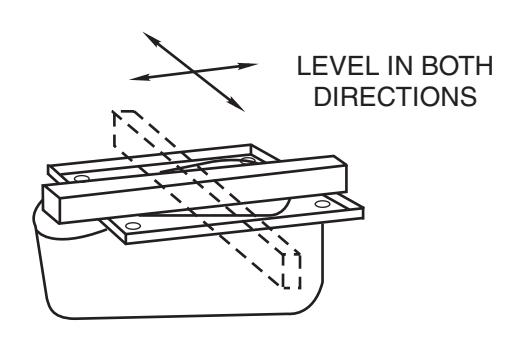
2. Install Cement Case in Floor
- A. For floor plate application: Cement case is set 1/8" (3.2mm) below floor level.
- B. For 1/2" high threshold application only: Cement case is set flush with floor. (Longer spindle must be used).
- C. Set cement case in floor and block in position. LOCATE CLOSER SPINDLE USING DIM "A".
- D. Case should be parallel with center line of door.
- E. CEMENT CASE SHOULD BE LEVEL. Place levels per Illustration.
- F. Grout in cement case with closer. Cement should not get between closer and case.
327 Floor Closer

3. Hang Door
- A. Mortise door and jamb for butts or hinges per template.
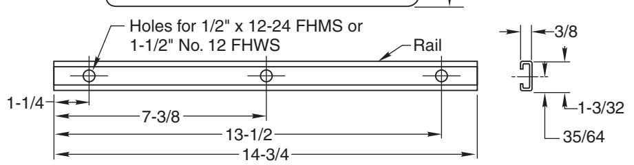
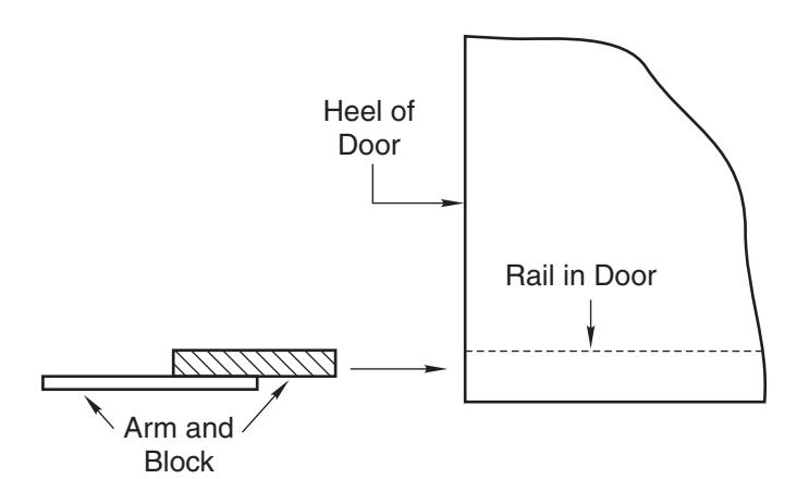
- B. Install rail in door per template (rail must extend to hinge edge of door so arm block may be placed in rail after door is hung.)
- C. Secure rail in place and hang door on its hinges. Use a plumb line to assure that door is in vertical alignment.
4. Attach Arm
- A. Close latch and stroke valves (Turn Clockwise).
- B. Slide arm block into rail through heel edge of door.
- C. With door almost closed slide arm onto spindle thru notch in end of arm. (Rock door back and forth to seat arm on spindle.)
- D. Secure arm to spindle with screw furnished. THE ARM SCREW MUST BE FASTENED SECURELY. (Tighten screw by rocking door back and forth.)
3
The ASSA ABLOY Group is the global leader in access solutions. Every day we help people feel safe, secure and experience a more open world.

Closer Adjustment
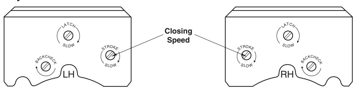
Closing speeds can be adjusted to suit local conditions and requirements. Label on closer face designates the purpose of each adjustment screw.
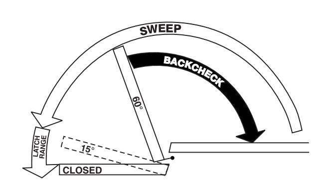
- A. The Stroke valve allows adjustment from open position to 15°.
- Latch valve allows adjustment from 15° to closed position.
- C. Important: Backcheck adjustment must be adjusted to vary resistance from light to firm at 60° of door opening. -*
- This closer is NON-HOLD-OPEN-factory set, no hold-open adjustment. * FAILURE TO DO SO MAY RESULT IN DAMAGE TO THE CLOSER AND RELATED HARDWARE
NOTE: WITH INDEPENDENTLY HUNG DOORS, ON 327 CLOSER, AN OPTIONAL HEAVY DUTY DOOR STOP IS REQUIRED.
Spring Power Adjustments
| Closer | Door Location | Maximum | |
|---|---|---|---|
| Number | And Function | Door Width | |
| ı | Interior | not over 4'0" | |
| no. 327 | Outswinging | not over 3'6" | |
| Entrance, Vestibule | |||
| • | Inswinging Entrance | not over 3'2" |
- Disconnect arm from spindle and swing door clear of closer.
- Remove floor plate or threshold cover.
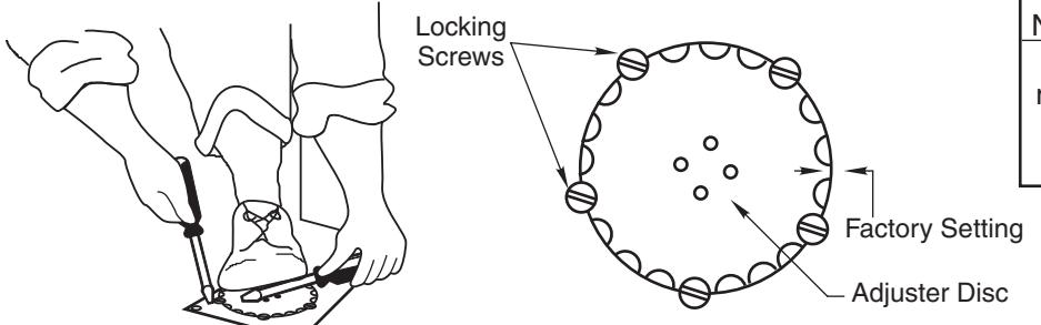
- Insert wrench pins into holes in adjuster disc.
- HOLD WRENCH FIRMLY WITH BOTH FOOT AND HAND.
- E. Loosen the adjuster locking screws enough to allow the adjusting disc to revolve.
- Wind or unwind spring one notch and never more than two beyond factory setting.
- Tighten adjuster locking screws.
- H. Replace floor plate or threshold. Attach arm securely.
Technical Product Support: Monroe, NC 28112 USA Phone: 877.974.2255 ext: 2
Techsupport.NortonRixson@assaabloy.com
NortonRixson.com