Norton Rixson 2800ST Cam Action Door Closer Push & Pull Side, Door or Frame Mounted Non-Hold Open and Hold Open …_80-9328-0002-020
Open the original PDF document
View PDFPush and Pull Side, Door or Frame Mounted Non-Hold Open and Hold Open Installation Instructions


WARNING
This product can expose you to lead which is known to the state of California to cause cancer and birth defects or other reproductive harm. For more information go to: www.P65warnings.ca.gov.
CAUTION
An incorrectly installed or improperly adjusted door closer can cause property damage or personal injury. These instructions should be followed to avoid the possibility of misapplication or misadjustment.
Hold open units are not permitted to be installed in fire door assemblies.
NOTES:
- ‒ For special applications a separate door and frame preparation template is packed with these instructions.
- ‒ Use this instruction sheet for installation sequence and closer adjustments only.
- ‒ Use of an auxiliary door stop is always recommended.
READ AND FOLLOW ALL INSTRUCTIONS. SAVE THESE INSTRUCTIONS.

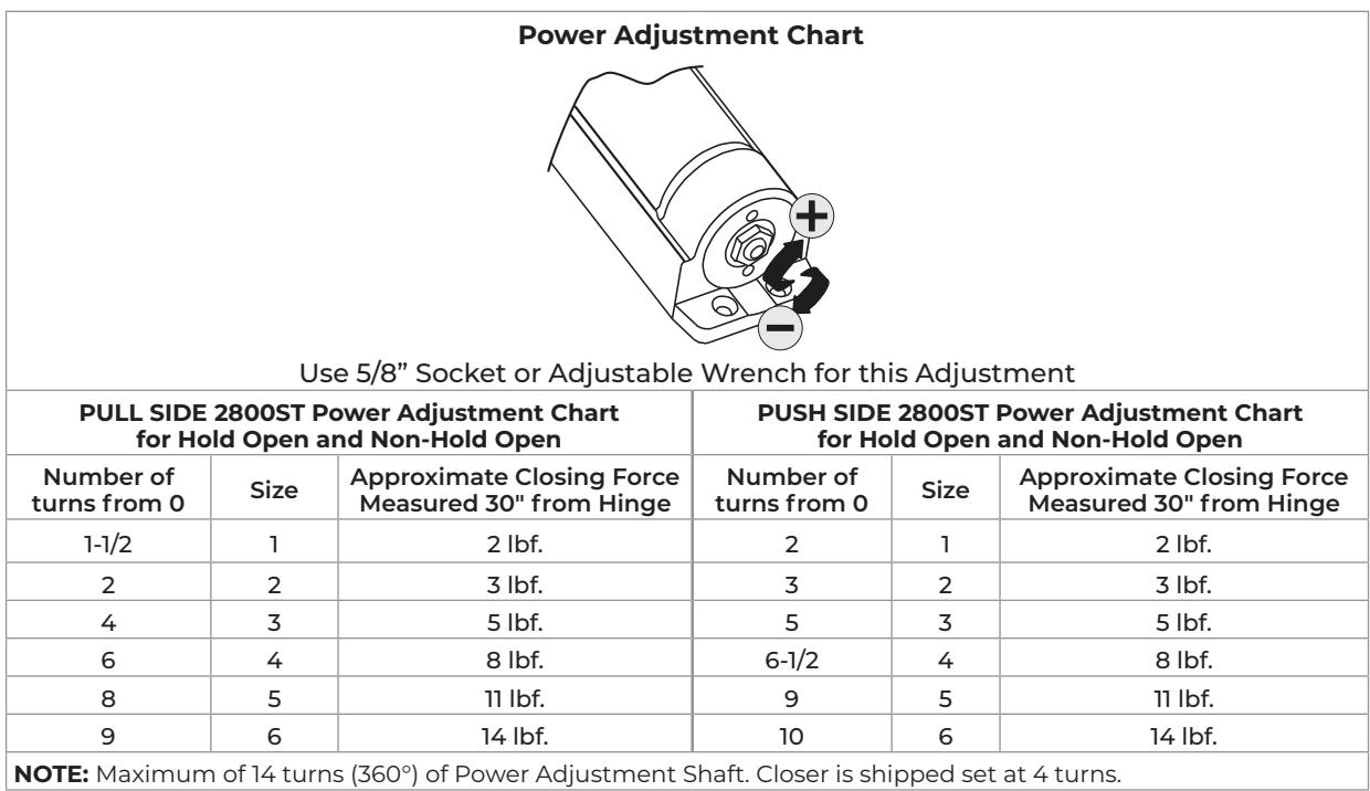
The closing force for Series 2800ST door closers is adjustable from a size 1 to a size 6, as outlined in ANSI Standard A156.4. When these series of door closers are installed and adjusted to conform to ADA reduced opening force requirements (5 lbs max.) for interior doors, they may not have adequate closing force to reliably close and latch the door. Power adjustments charted on Page 2 are recommended where possible, to ensure proper door control.
Copyright © 2023, 2024, ASSA ABLOY Accessories and Door Controls Group, Inc. All rights reserved. Reproduction in whole or in part without the express written permission of ASSA ABLOY Accessories and Door Controls Group, Inc. is prohibited.

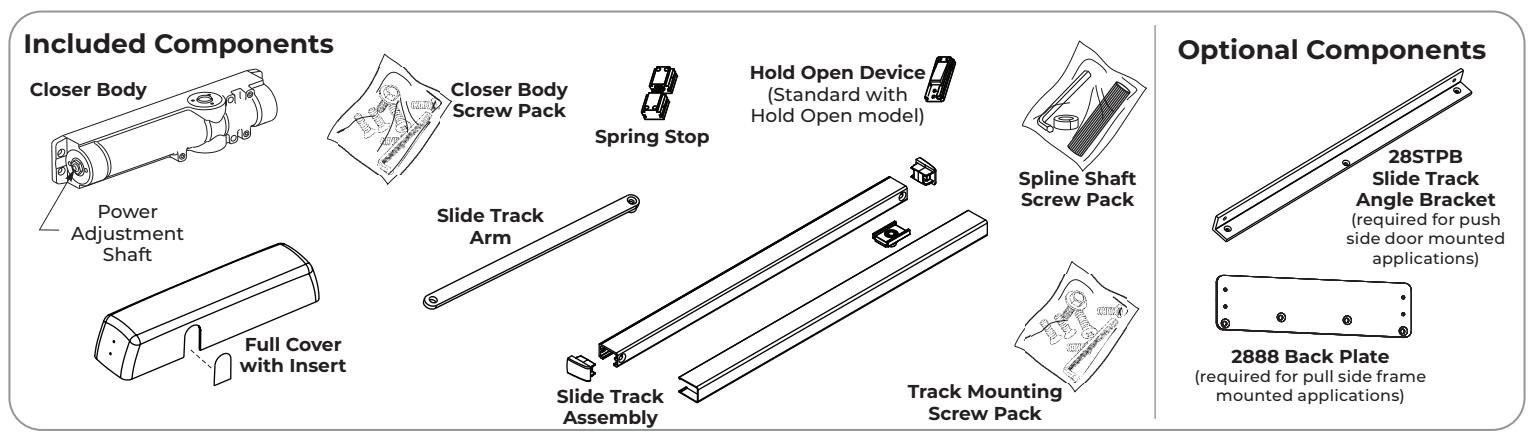
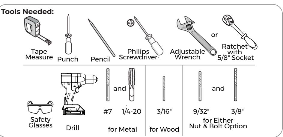
Supplied Hardware
| Fasteners | Door or Frame | Drill Sizes | |
|---|---|---|---|
| Standard | Closer: 1/4" Self-Drilling Screw (Closer Body Only) |
Aluminum
Metal or Wood |
3/16" (4.8mm) pilot hole required |
|
Track:
#12-14 Self-Drilling Screw (Track Only) |
3/32 " (2.4mm) pilot hole required | ||
|
Closer:
1/4-20 Machine Screw |
Metal |
Drill #7 (.201 dia. or 5.10mm)
Tap 1/4-20 |
|
|
Track:
#12-24 Machine Screw |
Drill 4.4mm or #16 (.0172")
Tap #12-24 |
||
| Optional |
Closer Body Only:
Sleeve Nut and Bolt (SNB) |
Hollow Metal |
9/32" (7.0mm) thru
3/8" (9.5mm) door face opposite to closer |
| Aluminum or Wood | 3/8" (9.5mm) thru | ||
|
Closer Body:
Thru Bolt and Grommet Nut (TBGN) |
All |
9/32" (7.0mm) thru
3/8" (9.5mm) dia. x 3/8" (9.5mm) deep, door face opposite to closer |
|

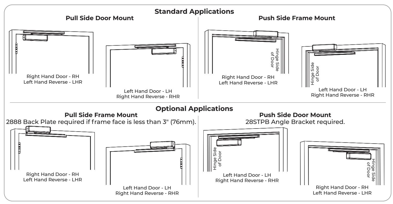
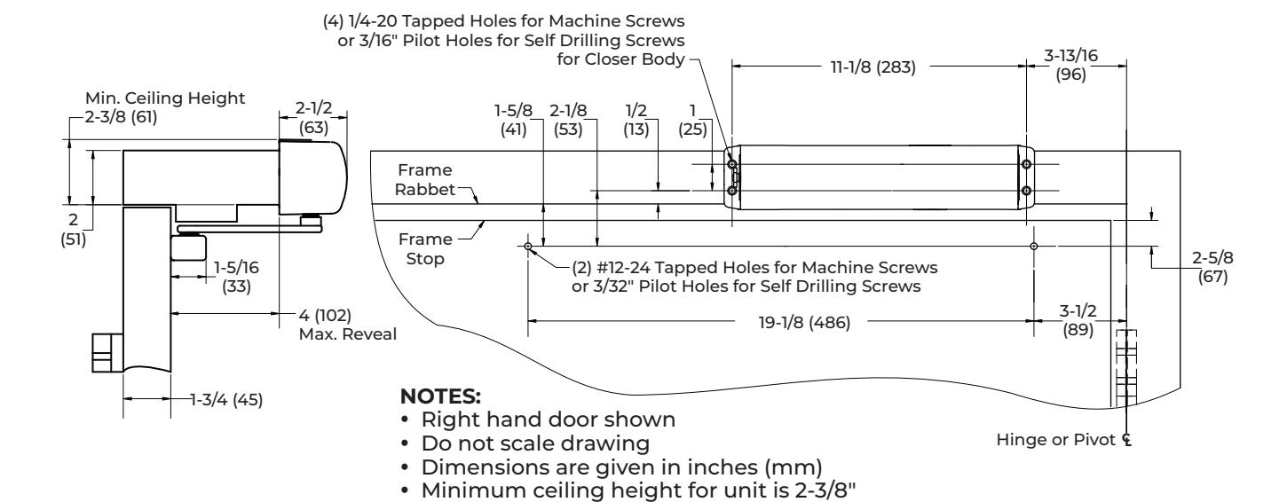
Pull Side Door Mount Installation
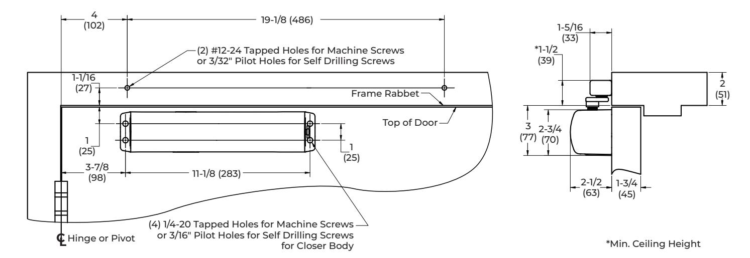
NOTES:
- Right hand door shown
- Do not scale drawing
- Dimensions are given in inches (mm)
- Minimum ceiling clearance for unit is 1-1/2" (39mm) from top of frame rabbet
-
Maximum door opening:
- 140° Max. Non-Hold Open and Hold Open track
Installation Sequence
-
Using the template above, locate the holes on the door and frame.
- Four (4) on door for closer
- Two (2) on frame face for track assembly.
- 2. Prepare door and frame for fasteners using the Supplied Hardware chart on page 2.
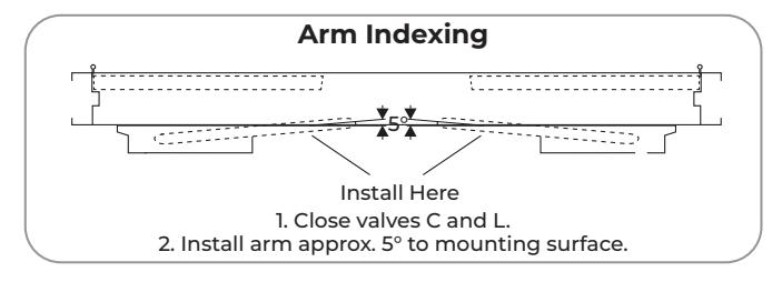
- 3. Close the "C" and "L" valves on the closer body.
- 4. Fasten the closer body to the door with power adjustment nut toward the lock edge of door.
- The slide track comes pre-assembled with the slider and end caps in place. If using a spring stop and/or hold open device, prepare the slide track assembly before proceeding. Refer to Adjustments on page 7
NOTE: The end caps secure the slider, spring stop, and/or hold open device in the slide track. Make sure the end caps are installed before securing the slide track assembly onto the frame with the provided screws.
- Fasten slide track assembly to frame face with open side facing down, and the spring stop and hold open device (if equipped) installed toward hinge edge of door.
- 7. Secure the arm to the spline shaft with the silver arm screw using the 4mm allen wrench provided.
- 8. With the arm parallel to the door, insert the spline shaft into the top of closer. The spline shaft will contact the gear inside the closer. For inclusive restroom/telephone booth function, refer to page 8.
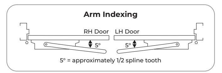
- Once the spline shaft and closer gear have made contact, rotate the arm approximately 5° (as shown in Arm Indexing chart above) until the spline shaft slides further into the closer gear.
- 10. Move the arm in position under the slider stud. Insert the 5mm hex wrench through the threaded hole in the arm and into hex on the stud. Rotate counterclockwise until tightened. (See Figure 1 on page 7)
- 11. Slide the spline vertically in or out of the closer up to 1/2 inch until arm is parallel to the track. Install plastic bushing on opposite side of spline shaft with the black screw provided.
- 12. Slowly open the "C" and "L" valves and allow door to close to the jamb.
- 13. Adjust closer power (see Pull Side power setting in the Power Adjustment Chart on page 2), closer valves, and Hold Open device (for 2800STH models). (See page 7)
Push Side Frame Mount Installation
y Maximum door opening:
(61mm)
- ‒ 110° Max. Non-Hold Open and Hold Open track without spring stop.
- y An auxiliary stop by others is required.
Installation Sequence
-
1. Using the template above, locate the holes on door and frame:
- ‒ Four (4) on frame face for closer.
- ‒ Two (2) on door for track assembly.
- 2. Prepare door and frame for fasteners using the Supplied Hardware chart on page 2.
- 3. Fasten the closer body to the frame face with power adjustment nut toward the lock edge of door.
- 4. Fasten the slide track assembly to door with open side facing up.
NOTES:
- ‒ This application will not use the spring stop; do not install in track.
- ‒ For 2800STH model only, install hold-open device in track. Refer to the DC152 document or Figure 6 on page 7 for proper orientation.
- 5. Secure the arm to the spline shaft with the silver arm screw using the 4mm hex wrench provided.
- 6. Close the "C" and "L" valves. See Arm Indexing figure.
- 7. With arm parallel to door, insert spline into the bottom of closer. The spline will contact the gear inside the closer. For inclusive restroom/ telephone booth function, refer to page 8.
- 8. Once the spline shaft and closer gear have made contact, rotate the arm approximately 5° toward the door (as shown in Arm Indexing graphic) until the spline shaft slides further into the closer gear.
- 9. Open door slightly to gain access to top of slider in track assembly.
- 10. Move the arm in position over the slider stud. Insert the 5mm hex wrench through threaded hole in the arm and into hex on stud. Rotate counterclockwise until tightened. (See Fig. 1 on page 7.)
- 11. Slide the spline vertically in or out of the closer, up to 1/2" until the arm is parallel to the track. Install plastic bushing on the opposite side of the spline shaft with flat head screw provided.
- 12. Slowly open the "C" and "L" valves and allow door to close to the jamb.
- 13. Adjust closer power (see Push Side power setting in the Power Adjustment Chart on page 2), closer valves, and Hold Open device (for 2800STH models). (See page 7)

Pull Side Frame Mount Installation
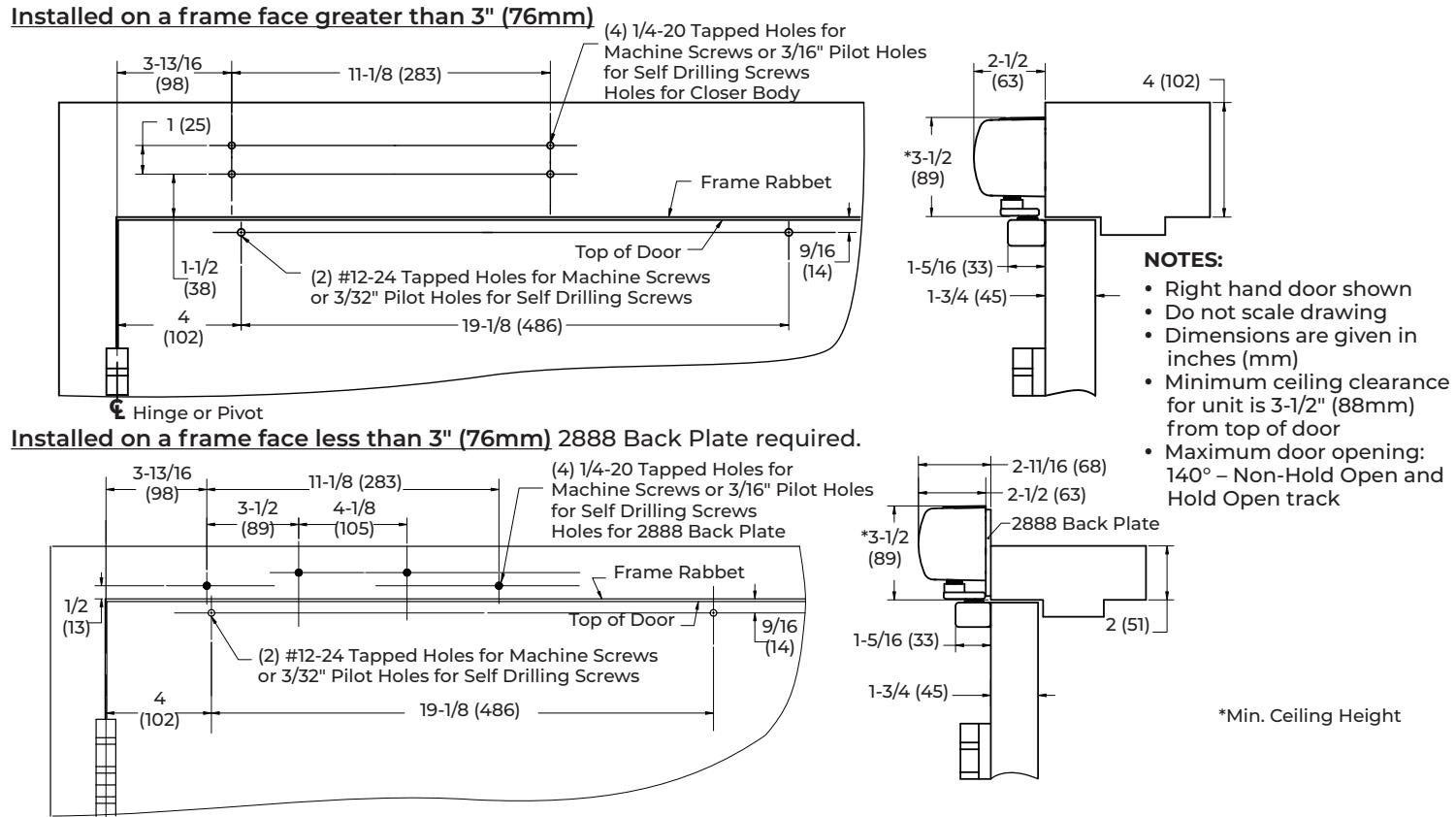
Installation Sequence CL Hinge or Pivot
NOTE: The 2888 Back Plate is required if the frame face is less than 3" (76mm).
-
1. Using the template above based on frame condition, locate the holes on the door and frame.
- ‒ Four (4) on frame face for closer or 2888 back plate.
- ‒ Two (2) on door for track assembly.
- 2. Prepare the door and frame for fasteners using the Supplied Hardware chart on page 2.
- 3. Secure the arm to the spline shaft with the silver arm screw using the 4mm allen wrench provided.
- 4. Close the "C" and "L" valves on the closer body.
- 5. Fasten the closer body to the frame with the power adjustment nut toward the lock edge of door.
- 6. With the arm parallel to the mounting surface, insert the spline shaft into bottom of the closer. The spline shaft will contact gear inside closer. For inclusive restroom/telephone booth function, refer to page 8.
- 7. Once the spline shaft and closer gear have made contact, rotate arm approximately 5° (as shown in Arm Indexing graphic above) until spline shaft slides further into the closer gear.
- 8. The slide track comes pre-assembled with the slider and end caps in place. If using a spring stop and/or hold open device, prepare the slide track assembly before proceeding. Refer to Adjustments on page 7
NOTE: The end caps secure the slider, spring stop, and/or hold open device in the slide track. Make sure the end caps are installed before securing the slide track assembly onto the door with the provided screws.
- 9. Fasten the slide track to the door with the open side facing up and spring stop and hold open device (if equipped) installed toward the hinge edge of the door.
- 10. Move the arm in position over the slider stud. Insert the 5mm hex wrench through the threaded hole in the arm and into hex on stud. Rotate counter-clockwise until tightened. (See Figure 1 on page 7)
- 11. Slide the spline vertically in or out of the closer up to 1/2 inch until the arm is parallel to the track. Install plastic bushing on the opposite side of spline shaft with black screw provided.
- 12. Slowly open the "C" and "L" valves and allow door to close to the jamb.
- 13. Adjust closer power (see Pull Side power setting in the Power Adjustment Chart on page 2), closer valves, and Hold Open device (for 2800STH models). (See page 7)

ASSA ABLOY
2800ST Cam Action Door Closer
Push Side Door Mount Installation
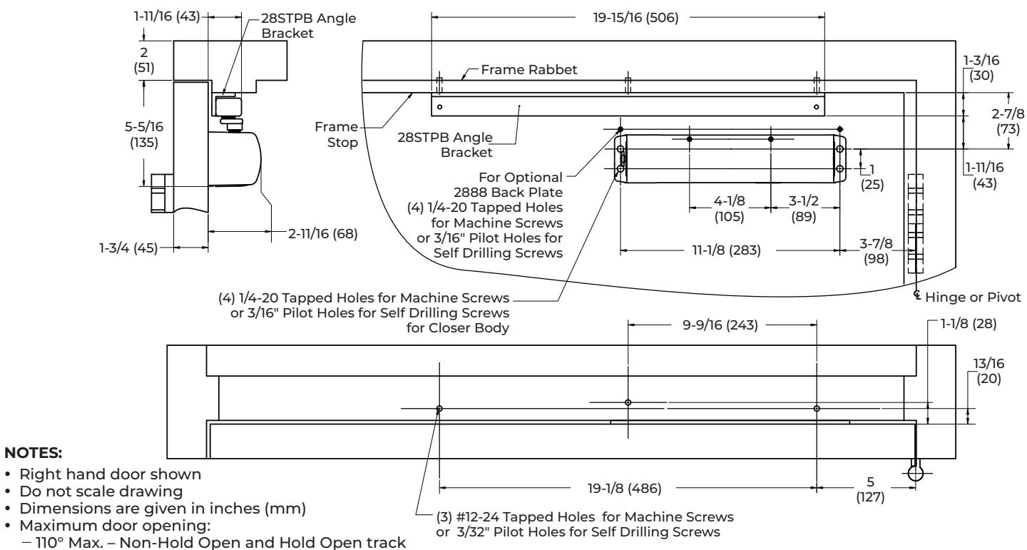
Installation Sequence
NOTE: The 28STPB Angle Bracket is required for this configuration.
-
Using the template above, locate the holes on door and frame:
- Four (4) on door for closer.
- Three (3) on frame soffit for the 28STPB angle bracket.
- 2. Prepare the door and frame for fasteners using the Supplied Hardware chart on page 2.
- 3. Secure the arm to the spline shaft with silver arm screw using the 4mm allen wrench provided.
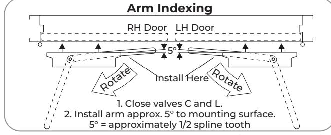
- 4. Close "C" and "L" valves. See Arm Indexing figure.
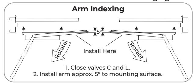
- 5. Rotate the arm as shown in the arm indexing graphic, and fasten the closer body to door with power adjustment nut toward lock edge of the door.
- 6. With power adjust nut toward the lock edge of the door and the arm parallel to the mounting surface, insert the spline shaft into top of the closer. The spline shaft will contact the gear inside closer. For inclusive restroom/telephone booth function, refer to page 8.
- 7. Once the spline shaft and closer gear have made contact, rotate arm approximately 5° toward the door (as shown in Arm Indexing chart above) until spline shaft slides further into the closer gear.
- 8. The slide track comes pre-assembled with the slider and end caps in place. If using a spring stop and/or hold open device, prepare the slide track assembly before proceeding. Refer to Adjustments on page 7
NOTE: The end caps secure the slider, spring stop, and/or hold open device in the slide track. Make sure the end caps are installed before securing the slide track assembly onto the frame with the provided screws.
- 9. Fasten the 28STPB angle bracket to the door frame as shown above. Attach the track to the angle bracket with the open side facing down and spring stop and hold open device (if equipped) installed toward the hinge edge of the door using black screws provided with the 28STPB angle bracket kit.
- 10. Move the arm in position under slider stud. Insert the 5mm hex wrench through threaded hole in the arm and into hex on the stud. Rotate counter-clockwise until tightened. (See Figure 1 on page 7)
- 11. Slide the spline vertically in or out of the closer up to 1/2" until the arm is parallel to the track. Install plastic bushing on the opposite side of spline shaft with black screw provided.
- 12. Slowly open the "C" and "L" valves and allow door to close to the jamb.
- 13. Adjust closer power (see Push Side power setting in the Power Adjustment Chart on page 2), closer valves, and Hold Open device (for 2800STH models). (See page 7)

Adjustments
Arm Attachment to Track Slider:
Move arm in position under slider stud. Insert 5mm hex wrench through threaded hole in the arm and into hex on stud. Rotate counter-clockwise until tightened. See Figure 1.
Closing Power
2800ST Models are fully adjustable. For proper sizing see chart on Page 2. To adjust closer power – See Figure 2. Increase or decrease power as necessary.
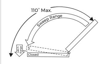
Closing Cycle (hydraulic control) See Figure 3A.
- Valve "L" controls door speed in Latch range.
- Valve "C" controls door speed in Sweep range.
Use 4mm hex-key furnished & adjust as shown in Figure 4.
Opening Cycle (hydraulic control) See Figure 3B.
Valve "B" cushions (slows) door opening in the back-check range.
NOTE: Never close this valve completely or damage to closer may occur.
Use 4mm hex-key furnished & adjust as shown in Figure 5.
Installation of Cover:
Architectural plastic cover: Slide cover over the closer and snap on.
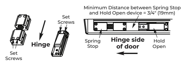
Spring Stop Opening Angle Adjustment:
The opening angle may be adjusted from 80 to 110 degrees by positioning the spring cushion assembly in the track. Refer to instructions included in the spring cushion package labeled "DC153".
NOTE: Spring stop must be installed on every configuration except the Push Side Frame Mount installation.
Hold Open Position/Power Adjustment:
If more or less hold open power is required, the power may be increased by turning the adjustment screws in the hold open device. Additionally, the hold open position may be adjusted from 80 to 110 degrees. Refer to instructions included in the hold open package labeled "DC152".
NOTE: Install spring cushion stop toward hinge then install hold open device. See Fig. 6 on this page.
Figure 1 - Arm Attachment to Track Slider
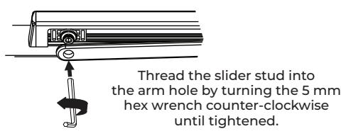
Figure 2 - Closing Power Control
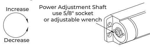
Figure 3 - Hydraulic Control
Backcheck Range Figure 3B: Opening Cycle
Figure 3A: Closing Cycle
Figure 4 - Closing Speed
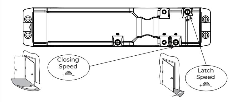
Figure 5 - Backcheck
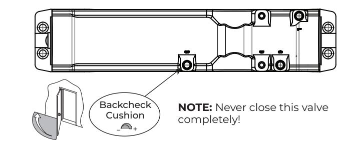
Figure 6 - Hold Open/Spring Stop

Setup for Inclusive Restroom/Telephone Booth Function
- 1. Open the door to the desired "propped" position.
- 2. With the arm parallel to the door, insert the spline shaft into the closer body.
- 3. Secure the arm to the slider stud using the 5mm hex wrench. Rotate counter-clockwise until tightened (see figure 1 on page 7).
- 4. Slide the spline vertically in or out of the closer up to 1/2" until arm is parallel to the track. Install plastic bushing on opposite side of spline shaft with the black screw provided.
- 5. Slowly open the "C" and "L" valves on the closer body.
- 6. Adjust closer power. See Power Adjustment Chart on page 2, closer valves and hold open device (for 2800STH models) on page 7.