Norton Rixson 27QT Series Removable Floor Closer, with Threshold, 3, 4 Offset Pivoted Installation Instructions_2700QT
Open the original PDF document
View PDF27QT Removable Floor Closer
with Threshold 3/4" Offset Pivoted - Handed Installation Instructions


27QT Removable Floor Closer
How To Determine Hand of Door
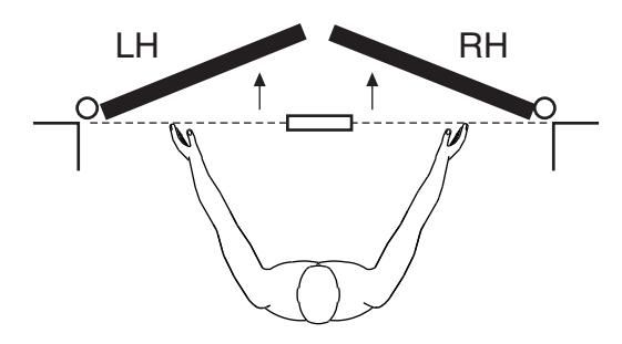
Face a door swinging open away from you. If it opens to the right, it is right hand. If it opens to the left, it is left hand.
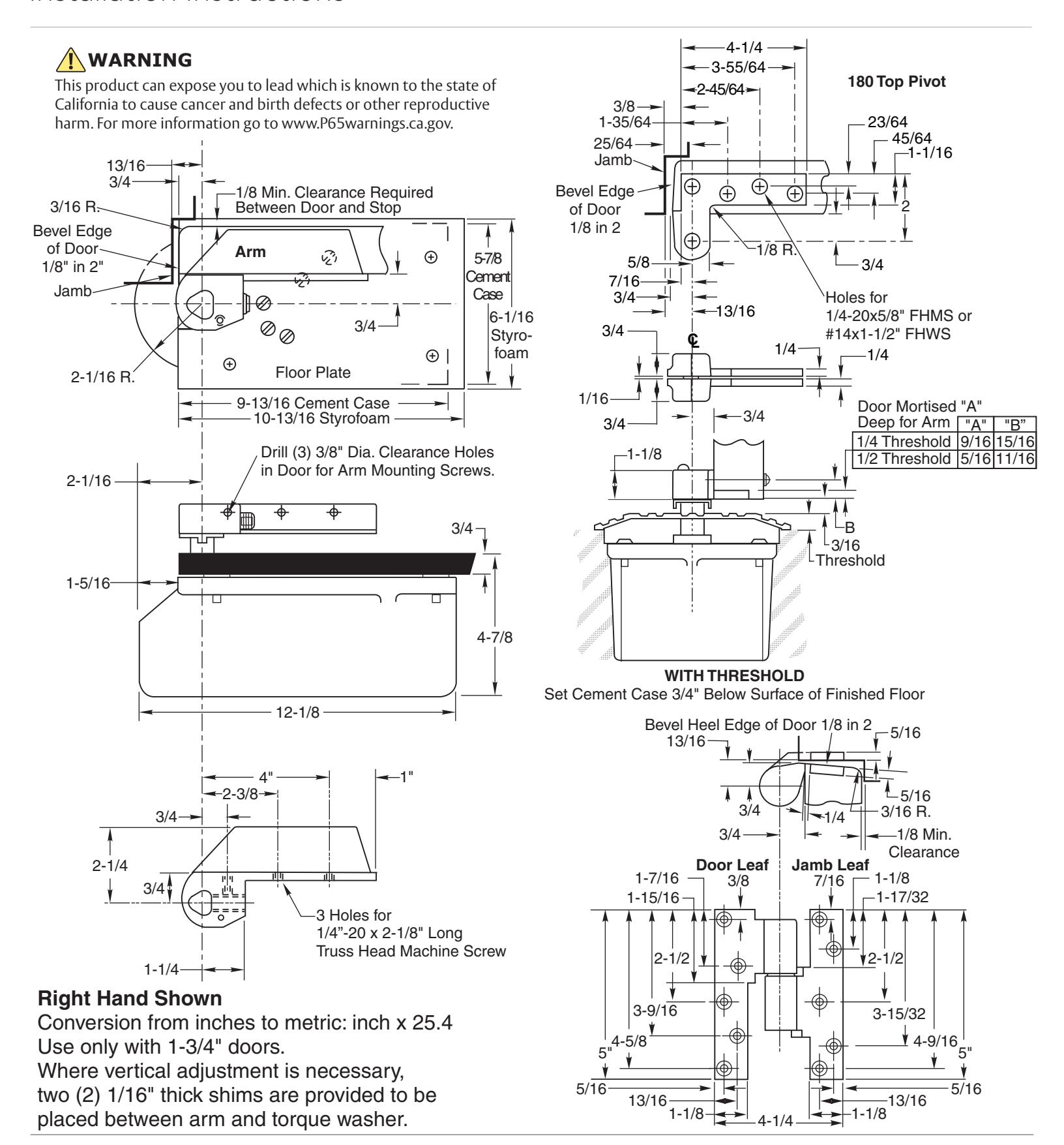
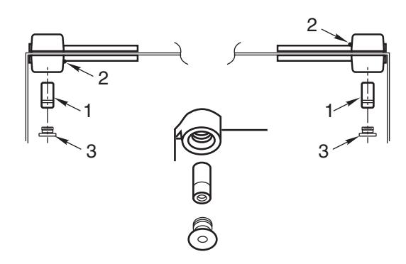
Arm Cap Arm Locking Set Screw 5/8-18UNF x 1" LG Top Pivot Jamb Portion Top Pivot Door Portion Intermediate Pivot (Side Jamb) Spindle Arm Knuckle IMPORTANT: Use plumb line to make sure that center line of top pivot pin lines up with center line of closer spindle.
1. Locating Closer
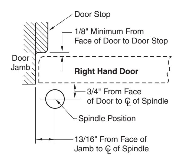
- A. Measure 13/16" out from door jamb.
- B. Allow 1/8" minimum clearance from door stop to door face. Measure door thickness. Add 3/4".
- C. Where lines meet determines center line of closer.
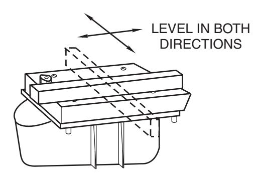
2. Install Cement Case in Floor
RIGHT HAND installation
- A. For floor plate application: Cement case is set 3/4" below floor level.
- B. Set cement case with styrofoam and closer attached in floor and block in position.
- C. Case should be parallel with center line of door.
- D. CEMENT CASE SHOULD BE LEVEL. Place levels per illustration.
- E. Grout in cement case with closer and styrofoam attached. Cement should not get between closer and case.
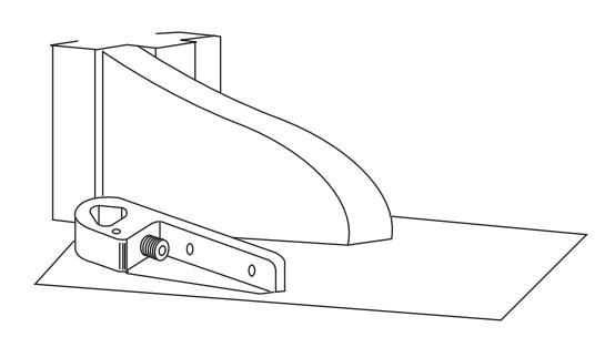
3. Install Top Pivot & Closer Arm
- A. Install top pivot in door per template.
- B. Install top pivot in frame per template.
- C. Center line of pivot should line up with center line of closer. Use plumb line as illustrated.
- D. See template for intermediate pivot. Use one pivot for doors up to 250 lbs. Use two pivots for doors between 250 and 400 lbs.
27QT Removable Floor Closer

4. Hang Door
CAUTION: Closer is shipped with "closing speed" valve down. DO NOT FORCE VALVE DOWN.
- A. Remove styrofoam and metal plate from closer.
- B. Attach top pivot and closer arm to door.
- C. Attach top pivot to frame.
- D. Set door on closer spindle. DO NOT FORCE DOOR CLOSED WHILE "CLOSING SPEED" VALVE IS TURNED DOWN.
- E. Push item 1 "top pivot pin" into place. Attach "cap" item 3. (Illustration) CAP MUST BE TIGHTENED SECURELY.
- F. Install intermediate pivots. (See intermediate pivot template)
- G. Close door to 60° or more and turn valve screw counterclockwise. Door will then close.
- H. While working door back and forth TIGHTEN ARM LOCKING SCREW SECURELY with wrench furnished.
- I. Put arm cap on arm and secure TIGHTLY with cap screw furnished.
The ASSA ABLOY Group is the global leader in access solutions. Every day we help people feel safe, secure and experience a more open world.

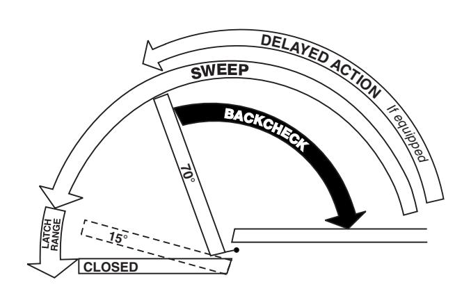
Closer Adjustment
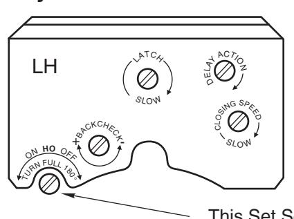
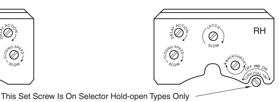
Closing speeds can be adjusted to suit local conditions and requirements. Label on closer face designates the purpose of each adjustment screw. Adjustments are for speed control.
- The Delay Action valve allows adjustment from full open to 65° closed position. (Optional)
- B. The Closing Speed valve allows adjustment from full open to 15° on units without the Delay Action feature.
- C. The Closing Speed valve allows adjustment from 65° to 15° closed position on closers with Delay Action feature.
- D. Latch valve allows adjustment from 15° to closed position.
- E. Important: Backcheck adjustment must be adjusted to vary resistance from light to firm at 60° of door open. Do not use Backcheck as deadstop. This is an intensity valve not speed control.
Closer Removal or Reinstallation
Before removing or installing closer, close down valve screws. When reinstalling, lock closer in hold-open position if provided.
Closer Removal:
- 1. Remove through bolts, arm cap and loosen arm locking screw.
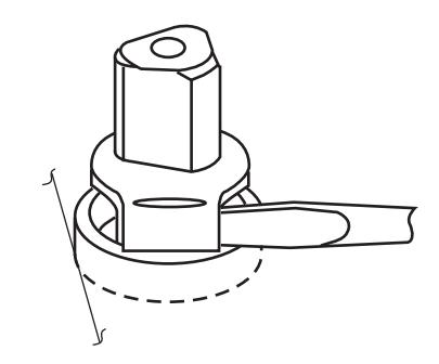
- Open door to hold-open or (approx.) 90° and close. (If non hold-open is being removed, insert a flat blade (10" min) screwdriver between spindle and torque washer to prevent spindle from turning.)
- 3. Remove arm, shim and torque washer from spindle.
- 4. With door open, remove threshold.
- 5. Remove closer mounting screws (4) and slide closer out under door.
Closer Reinstallation:
Reverse above procedure when reinstalling closer.
Before attaching arm, closer spindle must be in hold-open or rotated to 90°.
Non hold-open closers will require the use of a flat blade (10" min.) screwdriver to rotate the spindle.
Technical Product Support: Monroe, NC 28112 USA Phone: 800.438,1951 ext: 6030
Techsupport.NortonRixson@assaabloy.com
NortonRixson.com