Norton Rixson 210 Series Closer Hold Open Tri Packed Installation Instructions
Open the original PDF document
View PDF
- This sheet covers 3 installation options, select appropriate installation.
- · All measurements are to be made manually.
INSTALLATION INSTRUCTIONS
Power sizes 1 thru 6
Hold Open Models
Incorrect installation or adjustment could cause damage or injury. Read and follow instructions carefully.
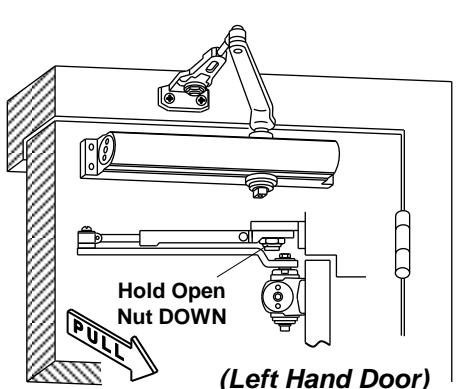
Option A – Regular Arm Installation
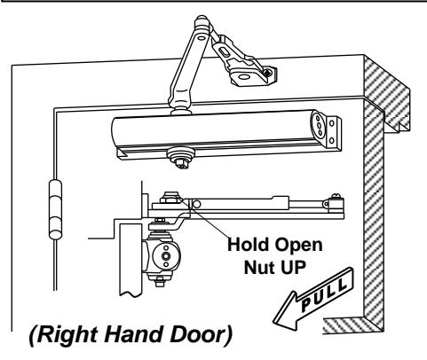
Option A instructions:
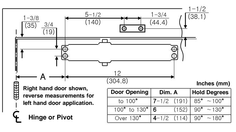
- 1. Select degree of opening from table and use template dimensions shown above. Mark four (4) holes on door for closer and two (2) holes on frame for arm shoe.
- Drill pilot holes in door and frame for #14 all-purpose screws or drill and tap for 1/4-20 machine screws.
- 3. Install adjustable forearm/arm shoe assembly to frame using screws (g) or (h).
- 4. Install main arm to top pinion shaft using screw (e).
- 5. Mount closer on door using screws (c) or (d).
SPRING POWER ADJUSTING NUT MUST BE POSITIONED AWAY FROM HINGE EDGE.
- Adjust length of adjustable forearm so that forearm is perpendicular to frame when assembled to preloaded main arm. Secure forearm to main arm with screw provided.
- Adjust closing speed, back check control and spring power of door, following instructions as shown page 2 "How To Adjust Spring Power".
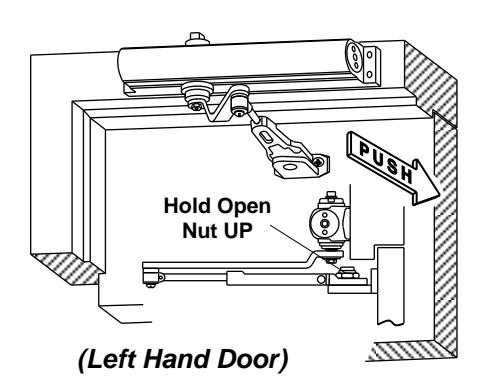
Option B – Top Jamb Installation
Inches (mm) Door Opening Dim. A Hold Degrees Hinge or Pivot to 100° (191)~100 Left hand door shown, 100° to 130 90 130 (152)reverse measurements for Over 130 (114)90° ~180 4-1/2 right hand door application. (304.8)-7/8(48)Φ (19) (13)(44.4)(140)
Option B instructions:
- Using the measurements from diagram A, mark screw hole center locations. Mark four (4) holes on frame to mount door closer and two (2) holes on door to mount shoe.
- 2. Drill pilot holes in door and frame, drill 3/16"(4.8mm) diameter holes for self tapping screws or drill and tap #7 (.201" diameter) for 1/4-20 machine screws.
- 3. Install adjustable forearm/arm shoe to door using screws (a) or (b).
- 4. Mount closer on frame using screws (c) or (d).
SPEED ADJUSTING VALVES MUST BE POSITIONED TOWARD HINGE SIDE.
- 5. Install main arm to bottom pinion shaft, perpendicular to door. Secure tightly with arm screw/washer (e).
- 6. Adjust length of forearm so that forearm is perpendicular to frame when assembled to preloaded main arm. Secure forearm to main arm with screw.
- 7. Adjust door's closing speed and power, see page 2 for reference.
- 8. Install cover using small screw (j).
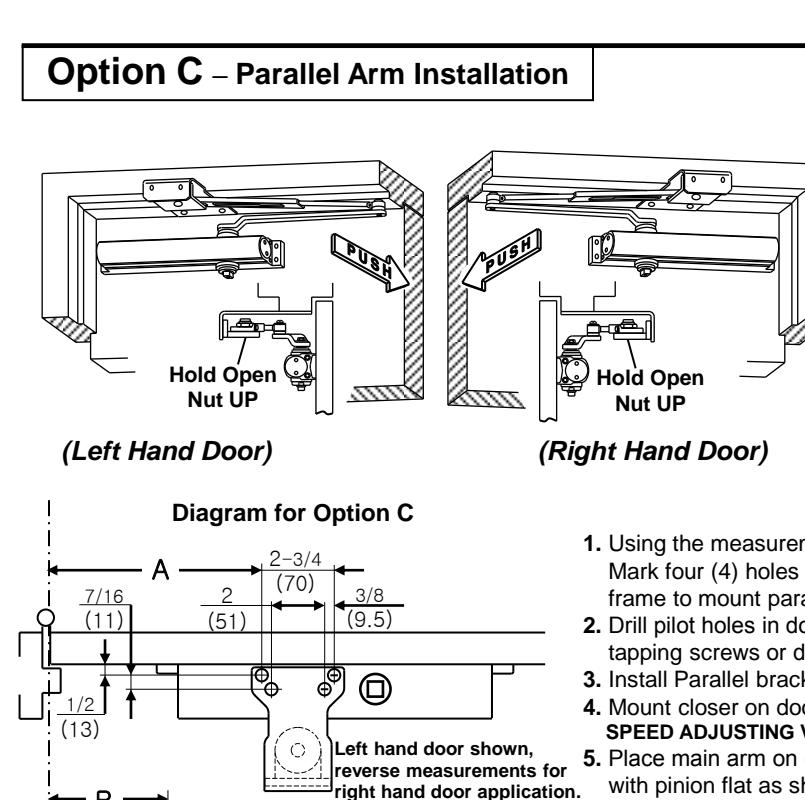
- 1. Using the measurements from diagram C, mark screw hole center locations. Mark four (4) holes on door to mount door closer and four (4) holes on frame to mount parallel bracket.
- 2. Drill pilot holes in door and frame, drill 7/32"(5.5mm) diameter holes for self tapping screws or drill and tap #7(.201" diameter) for 1/4-20 machine screws.
- 3. Install Parallel bracket to frame using screws (g) or (h).
- 4. Mount closer on door using screws (c) or (d).
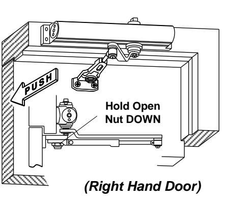
- SPEED ADJUSTING VALVES MUST BE POSITIONED AWAY FROM HINGE SIDE.
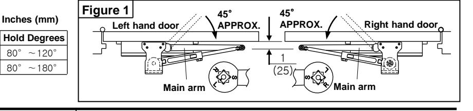
- 5. Place main arm on closer pinion shaft, indexing main arm mark "L" or "R" with pinion flat as shown in Figure 1. Secure tightly with screw/washer (e).
- 6. Remove arm shoe from forearm, install rod and forearm to bracket using the screw (g), (i).
- 7. With door closed, adjust length of forearm so that the tip of the main arm is approximately 1" (25mm) away from being parallel with door, when connected to the forearm. Secure with screw/washer (f).
- 8. Adjust door's closing speed and power, see below.
CLOSING CYCLE
9. Install cover using small screw (j).
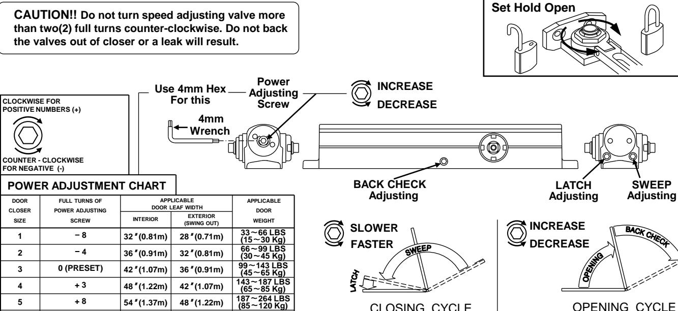
DOOR CLOSER ADJUSTMENT
0 o
(304.8)
Dim. A
9-1/2
(241)
Dim. B
(95)80° ~120
80°
3-3/4
(178) 1-1/4 (32)
(89)
(19)
Hine
or
Pivot
Door Opening
To 120
Over 120
CAUTION!! Do not turn speed adjusting valve more
54 " (1.37m)
58 " (1.47m)
48 "(1.22m)
54 " (1.37m)
264~330 LBS (120~150 Kg)
OPENING CYCLE
6
+ 11