Norton Rixson 20 Heavy-Duty Floor Closer 3, 4 Offset Pivoted – Handed, 180 Top Pivot – Non-Handed Installation …_20
Open the original PDF document
View PDF20 Floor Closer
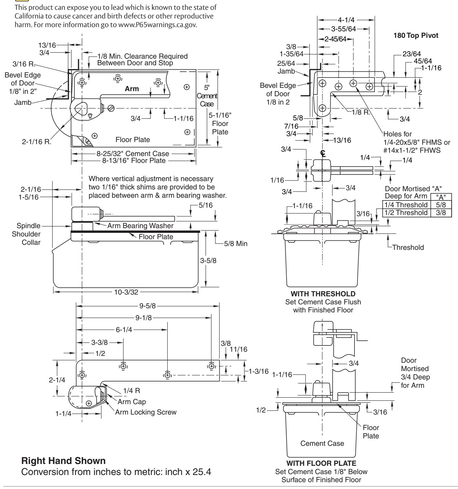
3/4" Offset Pivoted - Handed 180 Top Pivot - Non Handed Installation Instructions


How To Determine Hand of Door
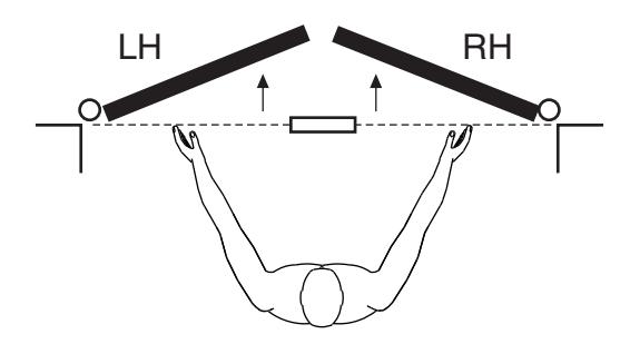
Face a door swinging open away from you. If it opens to the right, it is right hand. If it opens to the left, it is left hand.
Top Pivot Jamb Portion Top Pivot Door Portion Intermediate Pivot (Side Jamb) Arm Cap RIGHT HAND installation IMPORTANT: Use plumb line to make sure that center line of top pivot pin lines up with center line of closer spindle. Spindle Arm Knuckle Arm Locking Screw
1. Locating Closer
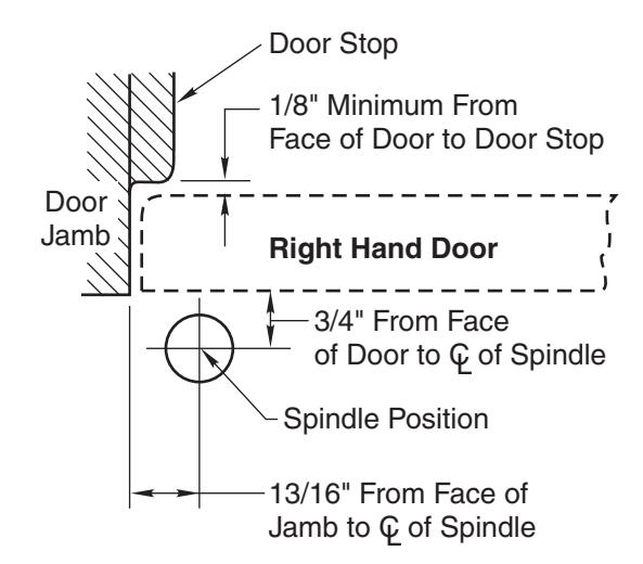
- A. Measure 13/16" out from door jamb.
- B. Allow 1/8" minimum clearance from door stop to door face. Measure door thickness. Add 3/4".
- C. Where lines meet determines center line of closer.
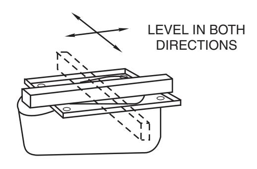
2. Install Cement Case in Floor
- A. For floor plate application: Cement case is set 1/8" (3.2mm) below floor level.
- B. For threshold application: Cement case is set flush with floor.
- C. Set cement case in floor and block in position.
- D. Case should be parallel with center line of door.
- E. CEMENT CASE SHOULD BE LEVEL. Place levels per Illustration.
- F. Grout in cement case with closer. Cement should not get between closer and case.
3. Install Top Pivot & Closer Arm
- A. Install top pivot in door per template.
- B. Install top pivot in frame per template.
- C. Center line of pivot should line up with center line of closer. Use plumb line as illustrated.
- D. If side pivot is used, see template for intermediate pivot.
- E. Install door closer arm in bottom of door per template.

4. Hang Door
4a
Right Hand Shown
4b
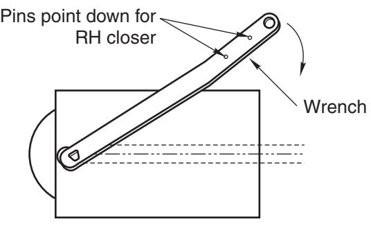
CAUTION: Closer is shipped with Closing Speed valve down. DO NOT FORCE VALVE DOWN.
- A. Using wrench, turn spindle until wrench is parallel with center line of closer. (Illustration 4a)
- B. Set door on closer spindle. DO NOT FORCE DOOR CLOSED WHILE "STROKE" VALVE IS TURNED DOWN.
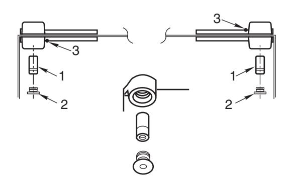
- C. Push item 1 "top pivot pin" into place. Attach "cap" item 2. (Illustration 4b) CAP MUST BE TIGHTENED SECURELY.
- D. Open Stroke valve (counterclockwise) one turn.
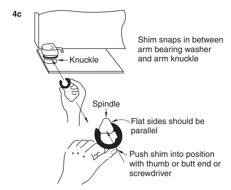
- E. If door drags at floor (or threshold, if used), raise door to desired clearance and insert one or more 1/16" shims. (Illustration 4c)
- F. While working door back and forth TIGHTEN ARM LOCKING SCREW SECURELY with wrench furnished.
- G. Put arm cap on closer spindle and secure TIGHTLY with cap screw furnished.

Closer Adjustment
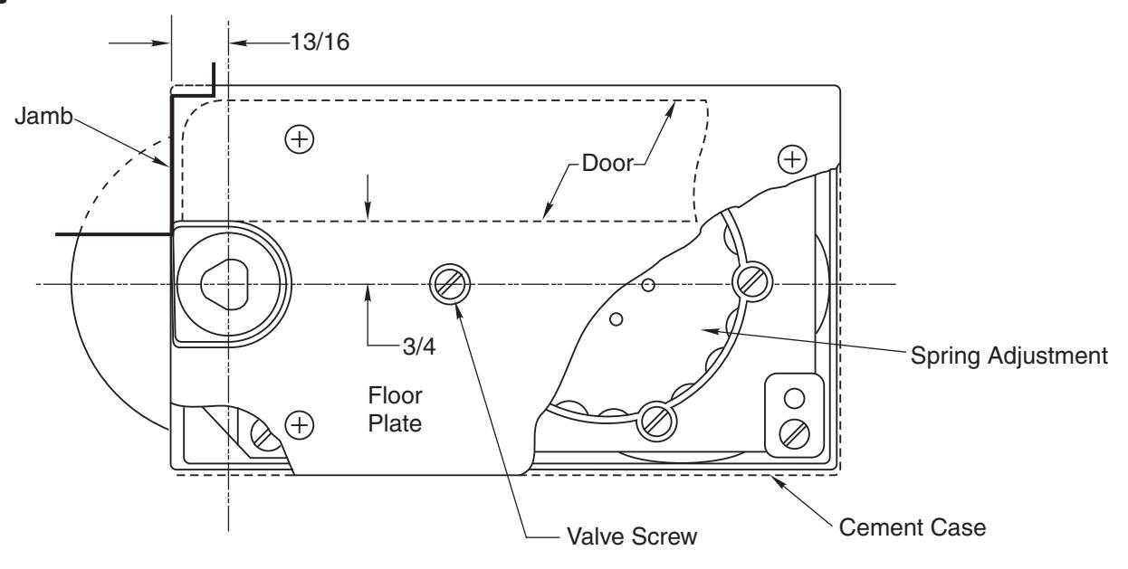
Closing speed can be adjusted to suit local conditions and requirements. With a screw driver turn the adjustment screw that projects through the floor plate or threshold, either in or out as the case may be until the desired action is attained. Turn this valve
screw to the right, clockwise, to decrease closing speed and to the left to increase the closing speed. FORCING THIS SCREW DOWN WILL IMPAIR ITS OPERATION. Important: Spindle centerline must be maintained.
Spring Power Adjustments
This closer can be adjusted for increased or decreased spring power.
These adjustments if required should be done by an authorized repair agency.
Repairs, parts replacement or internal adjustments must be done by a Norton Rixson authorized repair agency. Consult nortonrixson.com for an authorized repair agency in your area.