Norton Rixson 1600 Series UNI-1601, UNI-1603BC, UNI-1604BC UniTrol Non-Handed Door Closer Non-hold Open and Hold…_80-9316-2533-020
Open the original PDF document
View PDF1600 Series UniTrol Non-Handed Door Closer
Arm Models UNI-1601, UNI-1603BC, and UNI-1604BC

Installation Instructions
Non-hold Open and Hold Open (H) models, adjustable size 1-6 (UNI-1601(H) & model) and size 3 & 4 (UNI-1603BC(H) and UNI-1604BC(H) models). Hold open models are not UL-listed.


/ WARNING
This product can expose you to lead which is known to the state of California to cause cancer and birth defects or other reproductive harm.
For more information go to: www.P65warnings.ca.gov.
READ AND FOLLOW ALL INSTRUCTIONS. SAVE THESE INSTRUCTIONS.
| Arm Identification (Stamped on Arm) | ||||
|---|---|---|---|---|
| Door Width | Main Arm | Non Hold Open | Hold Open | |
|
28" - 32"
(0.70 - 0.80m) |
9-1/2"
(241mm) |
6100-11 | 6100-1 | |
|
33" - 41"
(0.85 - 1.00m) |
11"
(279mm) |
6100-13 | 6100-3 | |
|
42" - 48"
(1.05 - 1.20m) |
12-1/2"
(318mm) |
6100-14 | 6100-4 | |

1600 Series UniTrol Non-Handed Closer
ATTENTION:
An incorrectly installed or improperly adjusted door closer can cause property damage or personal injury. These installation instructions should be followed to avoid the possibility of misapplication or misadjustment.
- For special applications, a separate door and frame preparation template is packed with these instructions. Use this instruction sheet for installation sequence and closer adjustments only.
- Doors should be hung on ball bearing or anti-friction hinges
- Door and frame must be properly reinforced.
- Always consult door/frame manufacturer for fastener compatibility.
- Adjust closing time speed between 4 and 7 seconds from 90° to 0°. Use of door by handicapped, elderly or small children may require greater closing time.
- These door closers should NOT be installed on exposed side (weather side) of exterior doors.
- Dimensions are given in inches (millimeters).
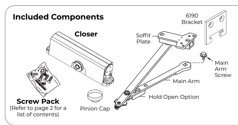
Supplied Hardware
| Mounting Hardware | Door or Frame | Drill | ||
|---|---|---|---|---|
|
Closer, Soffit Plate, 6190 Bracket:
1/4-14 x 1-1/2 Oval Flat Head Self Drilling Screw |
Wood/Metal | 3/16" (4.8mm) for wood | ||
| Soffit Plate, 6190 Bracket: 1/4-20 x 3/4 Oval Flat Head Mach. Screw | Metal |
Drill #7 (.201 dia. or 5.1mm)
Tap 1/4-20 |
||
|
Closer:
Sleeve Nut and Bolt (SNB) with 1/4-20 x 3/4 Oval Flat Head Mach. Screw (recommended) |
Hollow Metal |
9/32" (7.0mm) thru
3/8" (9.5mm) door face opposite to closer |
||
| Aluminum or Wood | 3/8" (9.5mm) thru | |||
| Danassassassassassassas |
Closer:
Thru Bolt and Grommet Nut (TBGN) (optional) |
All |
9/32" (7.0mm) thru
3/8" (9.5mm) dia. x 3/8" (9.5mm) deep, door face opposite to closer |
|
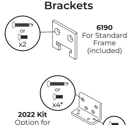
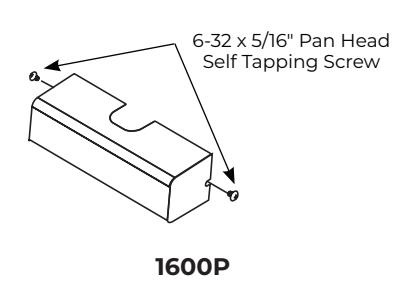
Reinforcing Kit
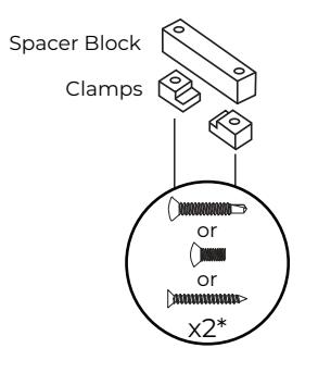
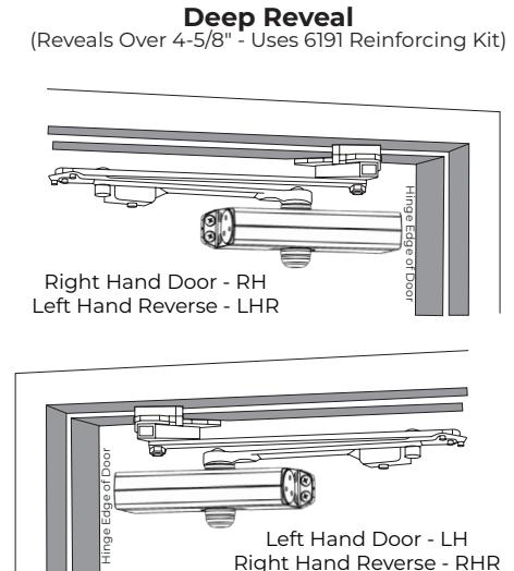
6191 Kit Option for Deep Reveal (Refer to Figure 2 on page 4) *screws included in 6191 Kit.
Drop Plates
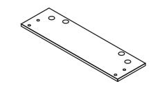
1688 Drop Plate For narrow top rail
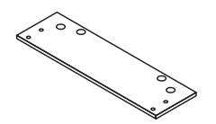
1688C Drop Plate For use with optional cover
Cover
x4*
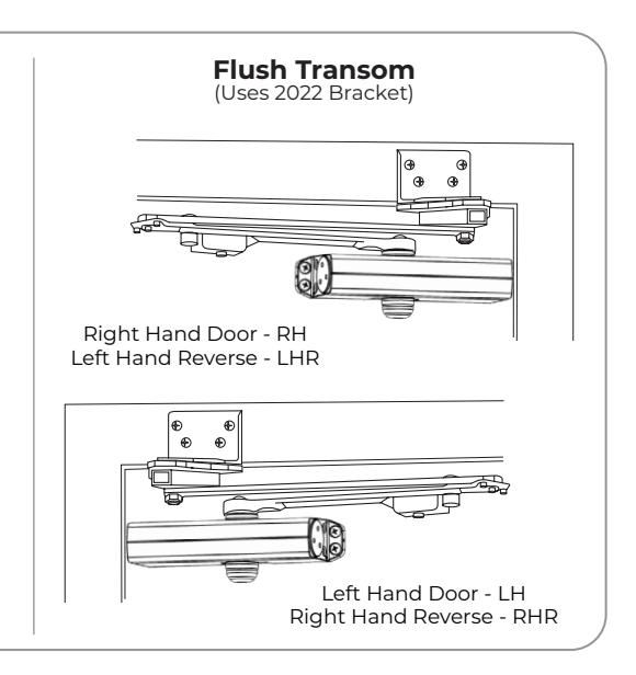
Flush Transom
*screws included in 2022 Kit.
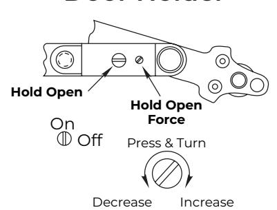
Door Holder

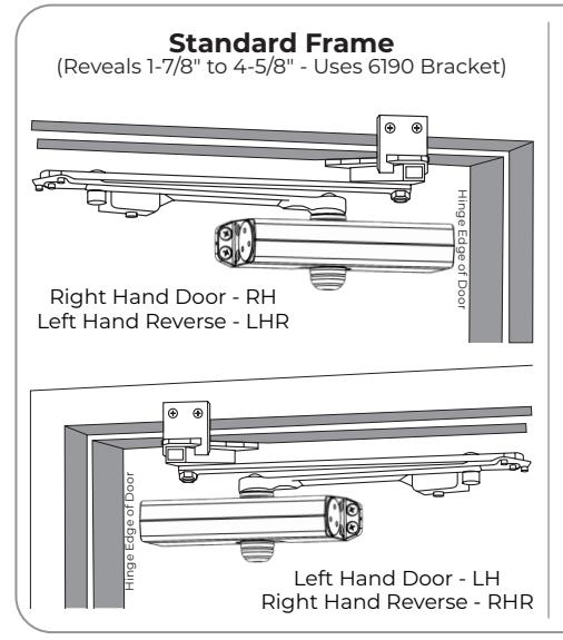
1600 UniTrol Arm - Templates (Right Hand Shown)
1-7/8" - 4-5/8" Standard Frame Reveal (With Door Template)
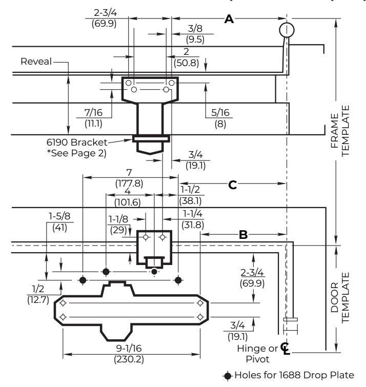
NOTES:
- 1. IMPORTANT: Door template is typical for all installations. Frame template must be selected according to frame reveal.
- 2. If top rail is as narrow as 2-5/8" (67mm) and prevents closer from being mounted directly to door surface, use 1688 Drop Plate. Prepare door and frame accordingly.
| 28" - 32" Wide Doors | ||||
|---|---|---|---|---|
| Opening | 1 | • | ||
| Hold Open | Stop | Α | В | С |
| 85° | 90° | 10-1/2 (267) | 8-5/8 (219) | 9-5/8 (244) |
| 90° | 95° | 9-3/4 (248) | 8 (203) | 9 (229) |
| 95° | 100° | 9-1/4 (235) | 7-1/2 (191) | 8-1/2 (216) |
| 100° | 105° | 8-7/8 (225) | 7-1/8 (181) | 8-1/8 (206) |
| 105° | 110° | 8-1/2 (216) | 6-3/4 (171) | 7-3/4 (197) |
| 110° | 115° | 8-1/8 (206) | 6-3/8 (162) | 7-3/8 (187) |
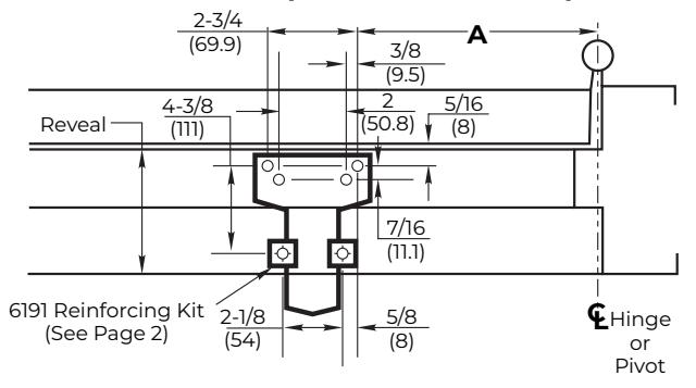
Over 4-5/8" Deep Frame Reveal Template
| 33" - 41" Wide Doors | ||||
|---|---|---|---|---|
| Opening | , | • | ||
| Hold Open | Stop | Α | В | C |
| 85° | 90° | 12-5/8 (321) | 11 (279) | 12 (305) |
| 90° | 95° | 12 (305) | 10-3/8 (264) | 11-3/8 (289) |
| 95° | 100° | 11-3/8 (289) | 9-3/4 (248) | 10-3/4 (273) |
| 100° | 105° | 10-7/8 (276) | 9-1/4 (235) | 10-1/4 (260) |
| 105° | 110° | 10-3/8 (264) | 8-3/4 (222) | 9-3/4 (248) |
| 110° | 115° | 10 (254) | 8-3/8 (213) | 9-3/8 (238) |
Flush Transom Template 2022 Bracket *See Page 2) -----------------------------------
| 42" - 48" Wide Doors | ||||
|---|---|---|---|---|
| Opening | , | |||
| Hold Open | Stop | A | В | С |
| 85° | 90° | 15 (381) | 13-1/4 (337) | 14-1/4 (362) |
| 90° | 95° | 14-1/4 (362) | 12-1/2 (318) | 13-1/2 (343) |
| 95° | 100° | 13-5/8 (346) | 11-7/8 (302) | 12-7/8 (327) |
| 100° | 105° | 13 (330) | 11-1/4 (286) | 12-1/4 (311) |
| 105° | 110° | 12-1/2 (318) | 10-3/4 (273) | 11-3/4 (298) |
| 110° | 115° | 12 (305) | 10-1/4 (260) | 11-1/4 (286) |
3
1600 Series UniTrol Non-Handed Closer
1600 UniTrol Arm Installation (Right Hand Shown)
1. Prepare door and frame.
- 1. Be sure that arm is correct for door width. See "Components" on page 1.
- 2. Be sure that correct frame and door template combination is used to prepare for installation. See "Templates" on page 3.
-
3. Using dimensions for hold-open or door stop angle desired, mark and drill
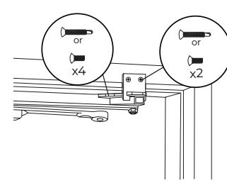
- y Four (4) holes on door for closer (or drop plate)
- y Six (6) holes on frame for soffit plate and 6190 bracket (See Figure 1) or
- y Six (6) holes on frame for soffit plate and 6191 reinforcing kit (See Figure 2) or
- y Four (4) holes on frame for 2022 angle bracket (See Figure 3)
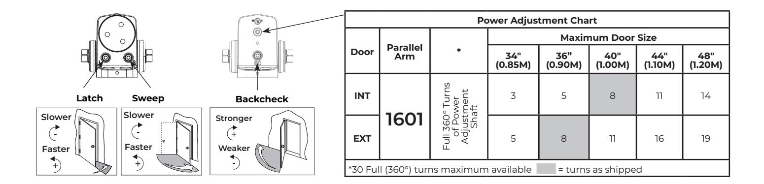
- 4. UNI1601 ONLY: Set approximate closing power using "Spring Power Adjustment" chart on page 5.
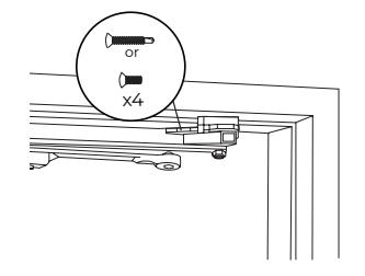
Figure 1. 1-7/8" - 4-5/8" Standard Frame With 6190 Bracket
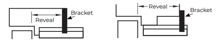
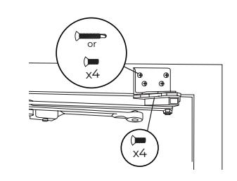
Figure 2. Over 4-5/8" Deep Reveal With 6191 Reinforcing Kit
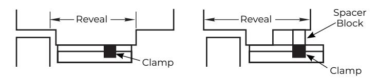
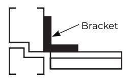
Figure 3. Flush Transom With 2022 Bracket
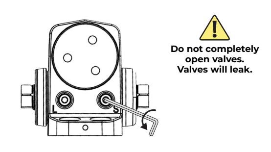
2. Close latch and sweep valves.
3. Install arm to frame.
Standard Frame 6190 Bracket
Deep Reveal 6191 Kit (Refer to 6191 Kit on page 2)
Flush Transom 2022 Bracket (Refer to 2022 Kit on page 2)
4. Mount drop plate (if used) and closer.
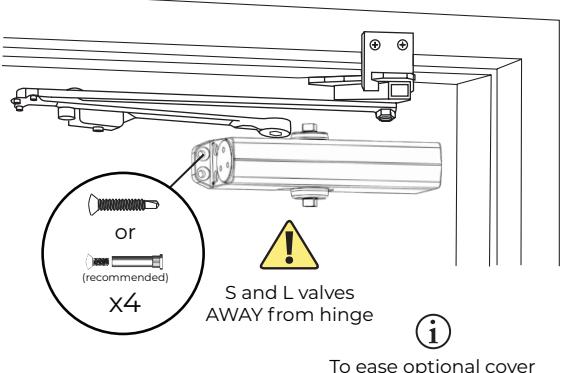
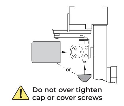
To ease optional cover installation, insert cover screws onto closer (leaving a slight gap) before mounting closer.
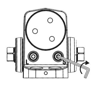
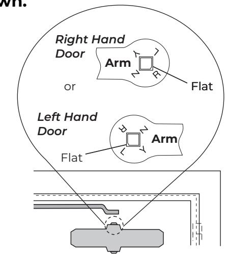
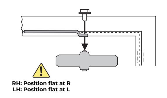
5. Rotate closer pinion to align flat as shown.
1600 Series UniTrol Non-Handed Closer

6. Attach arm to closer.
7. Open latch and sweep valves.
The 1600 UniTrol Arm Closer has now been installed.
• Continue with closer adjustments and decorative cap or cover installation.
Closer Adjustments

Use provided hex wrench to turn valves. NEVER force valves out of closer. NEVER completely close backcheck valve. Door must be open to adjust spring closing power. Refer to the chart.
Use of a power drill will void the Warranty.
Pinion Cap or Cover
Screw pinion cap onto pinion shaft by hand or with a Phillips screwdriver.
OR
Slide cover over closer and secure mounting screws after installation is complete.
5

Technical Product Support: Monroe, NC 28112 USA Phone: 877.974.2255 ext: 2 Techsupport.NortonRixson@assaabloy.com NortonRixson.com