Norton Rixson 147 and F147 Pivot Set, 3, 4 Offset, Handed Installation Instructions_IS-147
Open the original PDF document
View PDF147 or F147 Pivot Set
3/4" Offset, Handed Installation Instructions


WARNING
This product can expose you to lead which is known to the state of California to cause cancer and birth defects or other reproductive harm. For more information go to www.P65warnings.ca.gov.
Ce produit peut vous exposer au plomb qui, dans l'état de la Californie, est reconnu pour causer le cancer, des anomalies congénitales ou d'autres problèmes de reproduction. Pour plus d'informations, visitez: www.P65warnings.ca.gov.
IMPORTANT: It is responsibility of door and frame manufacturers to check hardware schedule and prepare doors and frames. The following instructions cover field prep.
1. Prepare opening.
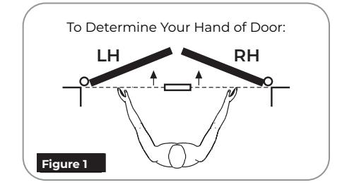
- 1. Determine hand of door for proper placement of pivot set. (Figure 1)
- 2. Confirm pivot side of door frame is both plumb and straight with respect to frame rabbet and frame face surfaces.
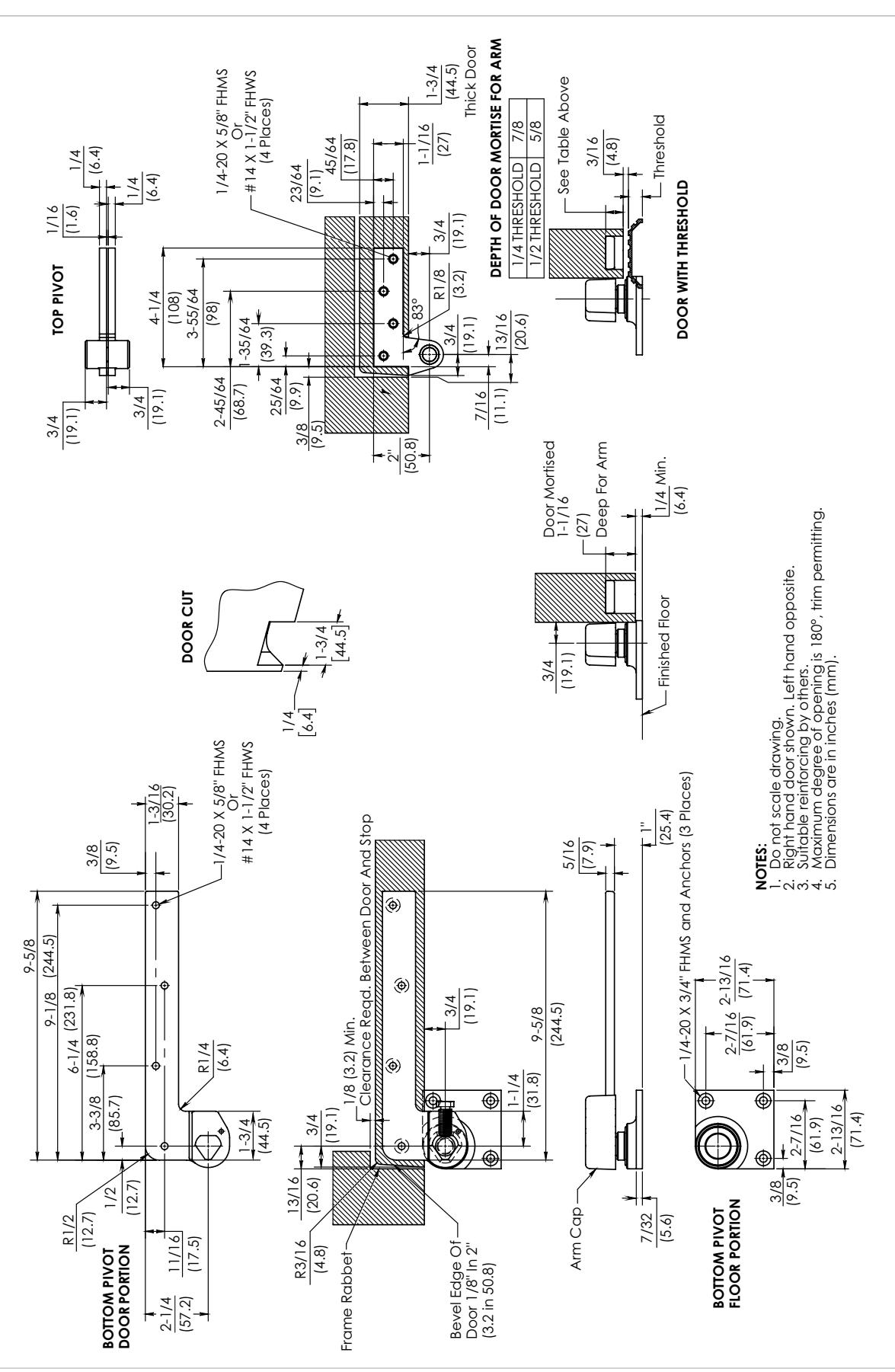
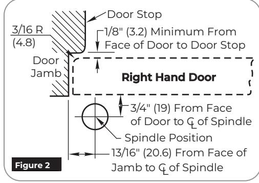
- 3. Mark frame header and door for top pivot. (Figure 2) Using template PS30300, note the requirement for door radius on heel edge of door.
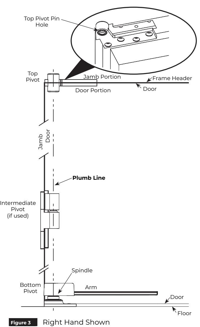
- 4. Install jamb portion of top pivot in frame header using four (4) 1/4-20 x 5/8" FHMS or #14 x 1-1/2" FHWS screws provided. (Figure 3)
- 5. Using Norton Rixson alignment tool 2604, secure plumb line to jamb portion top pivot pin. (Figure 3)
- 6. Using plumb line, locate bottom pivot floor portion spindle centerline. With bottom pivot floor portion as a template, mark location of mounting holes onto floor. (Figure 3)
NOTE: Confirm floor portion placement using template PS30300 with respect to frame rabbet and frame face. If not accurate, frame may not meet straight and plumb requirements of step 2 above.
147 or F147 Pivot Set

2. Prepare door.
- 1. Bevel pivot edge of door. Provide radius and minimum clearance specified per template PS30300.
- 2. Mortise and prepare holes in top of door for top pivot door portion and in bottom of door for bottom pivot door portion.
NOTE: Mortise depth in bottom of door must be coordinated with required clearance between door bottom and floor.
See template PS30300 for mortise depth with and without threshold.
3. If M19/M190 intermediate pivot is used, refer to IP50050 to prepare frame and door.
3. Install floor portion of bottom pivot.
- 1. Prepare floor to receive floor portion of bottom pivot.
- 2. Set provided anchors securely in floor.
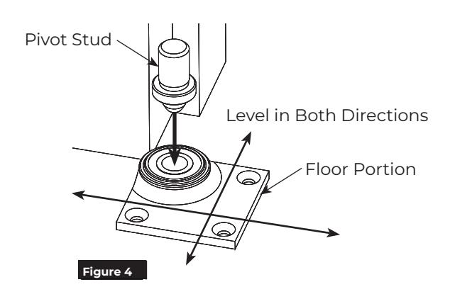
- 3. Install floor portion securely to floor using three (3) 1/4-20 x 3/4" FHMS. (Figure 4)
NOTE: Care must be taken that floor portion of bottom pivot is level.
4. Insert pivot stud in floor portion. (Figure 4)
4. Install top pivot and bottom arm into door.
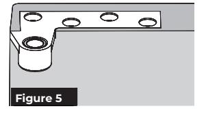
- 1. Install top pivot door portion using four (4) 1/4-20 x 5/8" FHMS or #14 x 1-1/2" FHWS screws provided. (Figure 5)
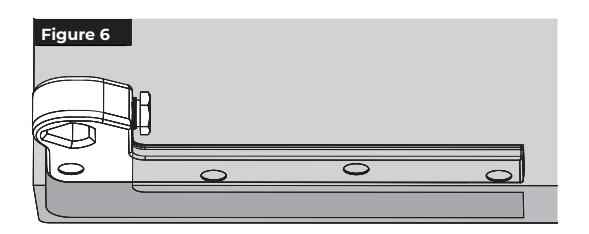
- 2. Install bottom arm into door using four (4) 1/4-20 x 5/8" FHMS or #14 x 2" FHWS screws provided. (Figure 6)
NOTE: Centerline of top pivot must align with centerline of bottom pivot stud. If door and frame is pre-prepped, follow steps 5 and 6 of "Prepare opening" to confirm this alignment requirement.

5. Hang door.

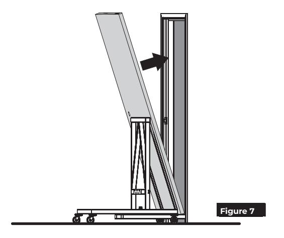
Caution: Know weight of door before attempting to install. Determine proper equipment needed to prevent door from falling. (Figure 7)
- 1. Set door on floor pivot stud and tilt top of door pivot portion into top jamb portion. (Figure 7)
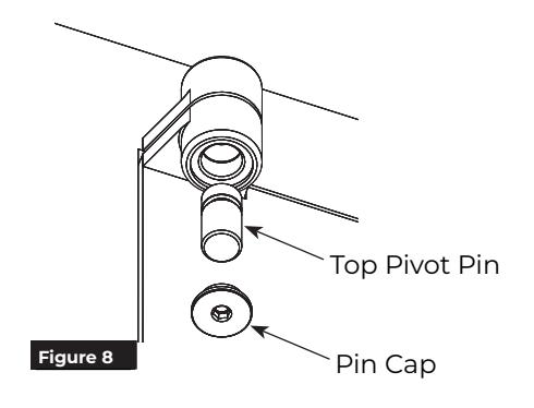
- 2. Push top pivot pin into place. (Figure 8)
- 3. Attach cap into top pivot pin using 3/16" hex wrench. (Figure 8)

Caution: Cap must be tightened securely.
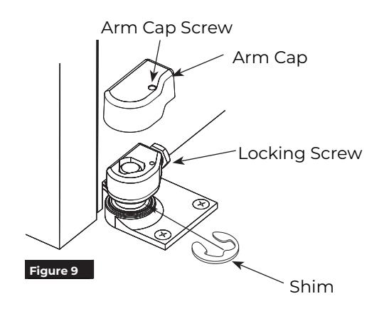
- 4. Tighten bottom pivot arm locking screw. (Figure 9)
- 5. If door drags at floor (or threshold, if used) loosen arm locking screw and raise door to desired clearance and insert one or more 1/16" (1.6) shims. Retighten arm locking screw securely. (Figure 9)
- 6. Place arm cap on arm and secure with cap screw furnished. (Figure 9)
- 7. If using intermediate pivot(s), install now. Refer to IS-(F)M19(0) installation instructions.


Caution: Know weight of door before attempting removal from frame. Determine proper equipment needed to prevent door from falling. (Figure 7)
- 1. If using intermediate pivot(s), remove pivot pin to detach door from frame portion of pivot.
- 2. Remove arm cap from bottom pivot and loosen arm locking screw.
- 3. Secure door so it will not fall from opening during following steps.
- 4. Remove door portion cap of top pivot.
- 5. Remove frame portion cap of top pivot.
- 6. With door securely held, carefully remove top pivot pin.
- 7. Leaning door at header to allow top of door to clear frame rabbet, lift door off of bottom pivot stud.
Technical Product Support: Monroe, NC 28112 USA Phone: 877.974.2255 ext: 2 Techsupport.NortonRixson@assaabloy.com NortonRixson.com