Norton Door Closers 161BF Series Closer Hold Open Installation Instructions
Open the original PDF document
View PDFINSTALLATION INSTRUCTIONS
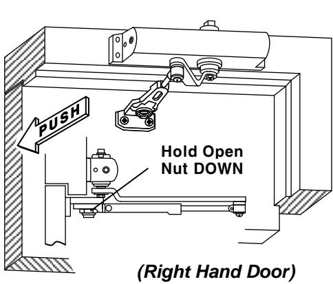
HOLD-OPEN ARM
Incorrect installation or adjustment could cause damage or injury. Read and follow instructions carefully.
Power size 1 thru 4
Inches (mm)
Option A – Regular Arm Installation
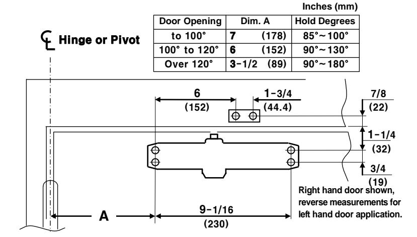
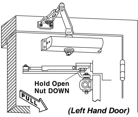
Option A instructions:
- 1. Select degree of opening from table and use template dimensions as shown. Mark four (4) holes on door for closer and two (2) holes on frame for arm shoe.
- 2. Drill pilot holes in door and frame for #14 all-purpose screws or drill and tap for 1/4-20 machine screws.
- Install adjustable forearm/arm shoe assembly to frame using screws (a) or (b) Reference page 2.
- 4. Install main Arm to top pinion shaft using screw (e).
- 5. Mount closer on door using screws (c) or (d).
- SPRING POWER ADJUSTING NUT MUST BE POSITIONED AWAY FROM HINGE EDGE.
- 6. Adjust forearm so that it is perpendicular to frame when assembled to preloaded main arm. Secure forearm to main arm with screw provided.
- 7. Adjust closing speed, backcheck control and spring power of door, following instructions as shown page 2.
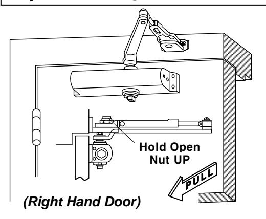
Option B – Top Jamb Installation
Door Opening Hold Degrees Dim. A Hinge or Pivot To 100° 7 -1/2 (191) 85°~100° Left hand door shown, 100° to 120° 90°~130° (152) reverse measurements for Over 120° 90°~180° 3-1/2 (89) right hand door application. 9-1/16 1-1/2 (230)(38) ė ( 3/4 1/2 (19) 1 - 3/4(13) (152) (44.4)
Option B instructions:
- 1. Select degree of opening from table and use template dimensions as shown Mark four (4) holes on frame for closer and two (2) holes on frame for arm shoe.
- 2. Drill pilot holes in door and frame for #14 all-purpose screws or drill and tap for 1/4-20 machine screws.
- 3. Install adjustable forearm/arm shoe assembly to door using screws (a) or (b) Reference page 2.
- 4. Mount closer body on frame using screws (c) or (d).
- 5. Install main arm to bottom pinion shaft, perpendicular to door. Secure tightly with arm screw/washer (e).
SPEED ADJUSTING VALVE MUST BE POSITIONED TOWARD HINGE SIDE.
- 6. Adjust length of forearm so it is perpendicular to frame when assembled to preloaded main arm. Secure forearm to main arm with screw.
- 7. Adjust door's closing speed and power, see page 2 for reference.
9-1/4 (235) 7 -5/8 (194)
7 -3/4 (197) 6 -1/8 (156)
5-3/4 (146) 4-1/8 (105)
To 100°
100° to 130°
Over 130°
¢
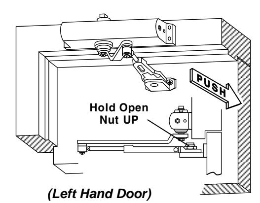
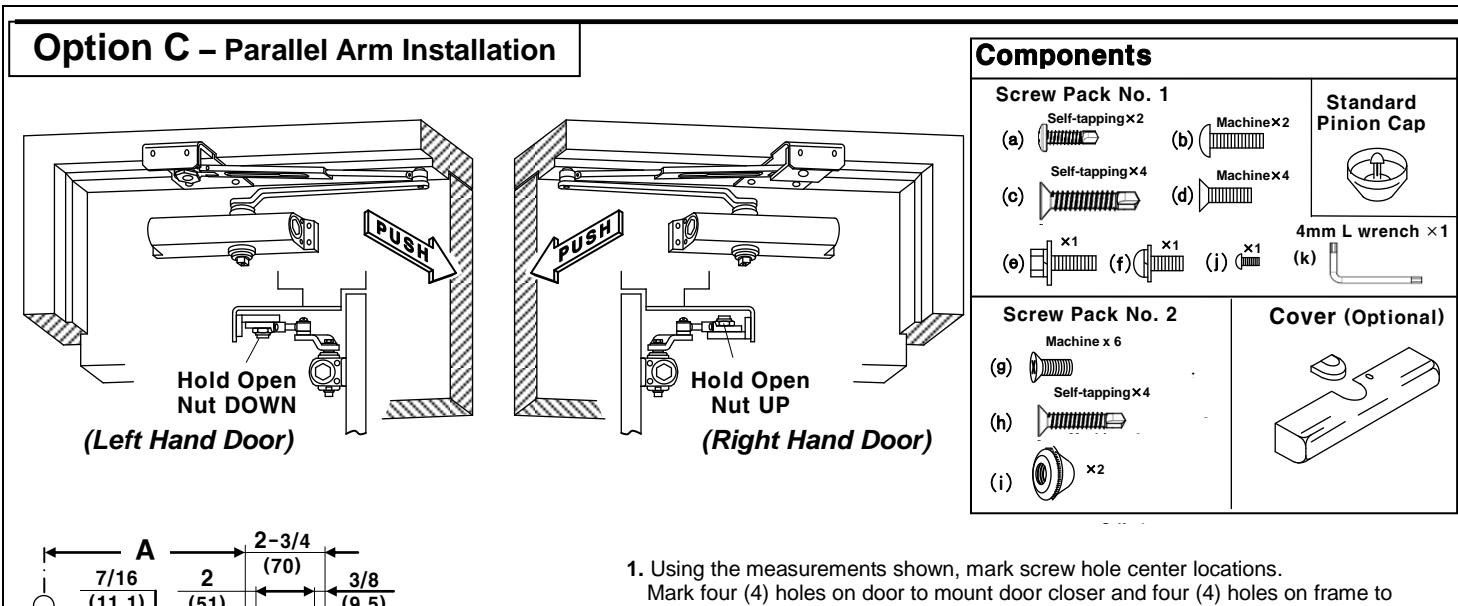
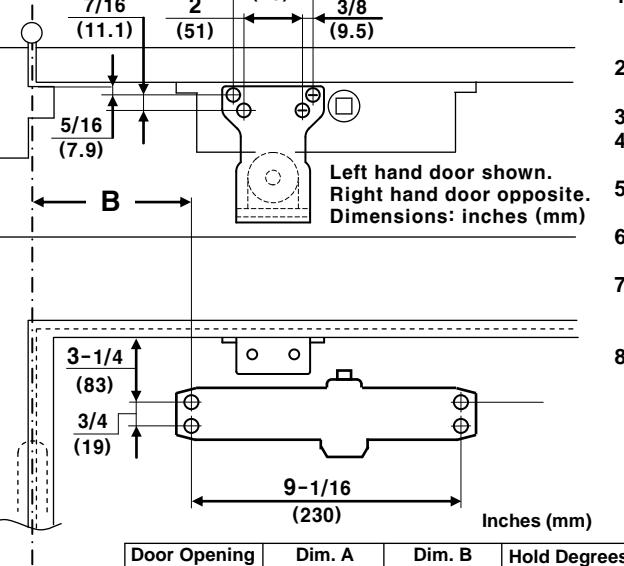
- mount parallel bracket.
- 2. Drill pilot holes in door and frame, drill 7/32" (5.5mm) diameter holes for self-tapping screws or drill and tap #7(.201" diameter) for 1/4-20 machine screws.
- 3. Install Parallel bracket to frame using screws (g) or (h).
- 4. Mount closer on door using screws (c) or (d). SPEED ADJUSTING VALVES MUST BE POSITIONED AWAY FROM HINGE SIDE.
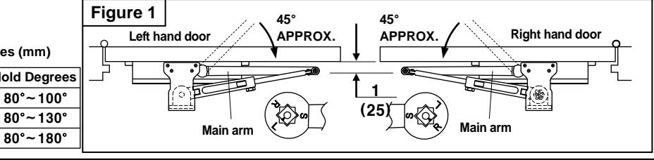
- 5. Place main arm on closer pinion shaft, indexing main arm mark "L" or "R" with pinion flat as shown in Figure 1. Secure tightly with screw/washer (e).
- 6. Remove arm shoe from forearm, install rod and forearm to bracket using the screw (g), (i).
- 7. With door closed, adjust length of forearm so that the tip of the main arm is approximately 1" (25mm) away from being parallel with door, when connected to the forearm. Secure with screw/washer (f).
- 8. Adjust door's closing speed and power, see below.
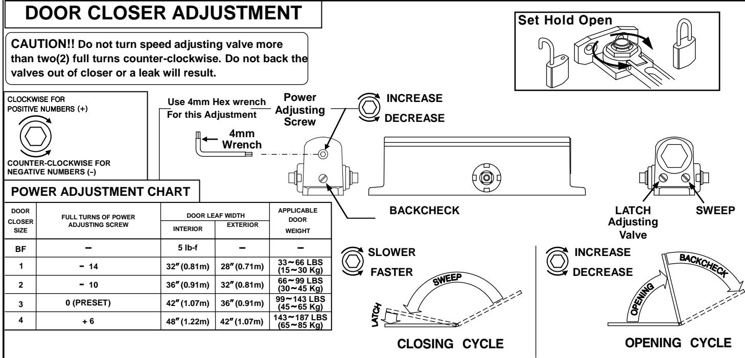

The closing force is adjustable from a size 1 to size 4, as outlined in ANSI Standard A156.4. When these series of door closers are installed and adjusted to conform to ADA reduced opening force requirements (5 lbs max.) for Interior doors, they may not have adequate closing force to reliably close and latch door. Power adjustments charted on this page are recommended where possible, to ensure proper door control.

By law the Americans with Disabilities Act (ADA) may require that door closer installation comply with accessibility guidelines.