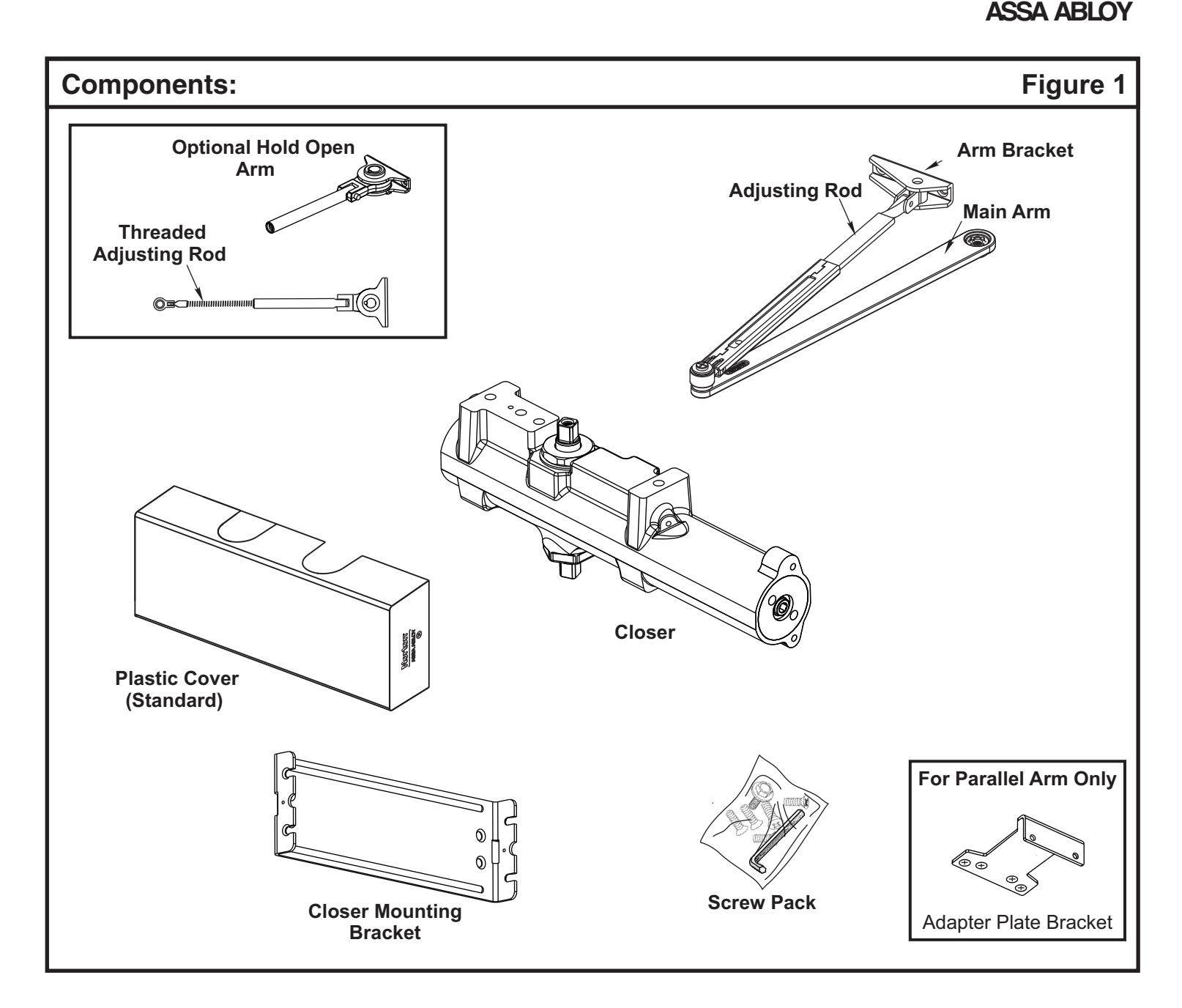
Norton 9500 Series Door Closer Tri-Style (Regular,Top Jamb,Parallel) Non-Hold Open or Hold Open Installation Instructions
Open the original PDF document
View PDF

ASSA ABLOY
ASSA ABLOY Multi-Sized 1 thru 6 Non-Hold Open and Hold Open Models 9500 Series Installation Instructions
80-9395-9511-020 REV-2 (08-16)
Regular Arm
Pages 5 & 6
Parallel Arm
Pages 7 & 8
Top Jamb Mount
Pages 9 & 10

IMPORTANT:
- An improperly installed or incorrectly adjusted door closer may cause property damage or personal injury; and will void product warranty.
- To avoid personal injury, DO NOT DISASSEMBLE THIS DOOR CLOSER BODY.
- Door closers must be securely fastened to a properly reinforced door and frame with fasteners provided.
- Door closers with the HOLD OPEN ARM option are not permitted to be installed in fire door assemblies.
BEFORE INSTALLING:

- The Americans with Disabilities Act (ADA) requires that doors having door closers have an opening force not to exceed 5 lbf. Use standard templating for regular arm and parallel arm applications. Jamb mounted applications use the template for 140° door opening to achieve the required opening force.
- The door closer's power size adjustment feature may require adjustment to its lowest setting to comply with ADA opening force guidelines.
- An auxiliary door stop, by others, is strongly recommended to avoid damage to the door closer and adjacent property.
- Doors should be hung on ball bearing or anti-friction hinges/pivots.
- Door closer must not be installed on the exterior of a door in an exterior wall of a building.
- ADA compliant closers
| Size of Door & Door Closer | |||||
|---|---|---|---|---|---|
|
Type
of Installation |
Interior |
Exterior
In-swinging |
Exterior
Out-swinging |
Recommended
Closer Size |
**Max.
Opening Force lbs/f |
|
Regular &
Top Jamb |
2'4"
3'0" 3'6" 4'0" 4'6" 5'0" |
2'6"
3'0" 3'6" 4'0" |
3'0"
3'6" 4'0" 4'6" |
1
2 3 4 5 |
8
14 16 22 24 26 |
|
Parallel
Arm |
2'4"
2'6" 3'0" 3'6" 4'0" 4'6" |
2'6"
3'0" 3'6" 4'0" |
1
2 3 4 5 6 |
8
14 16 22 24 26 |
|
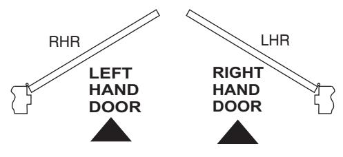
TO DETERMINE HAND OF YOUR DOOR:
** NOTE: These forces are for standard templating with bearing type hinges and do not accout for pressure differentials and draft.


| Preparation for Fasteners | Figure 2 | ||
|---|---|---|---|
| Fasteners | Door or Frame | Drill-Sizes | |
| Standard |
Aluminum
or Metal |
No drill required | |
| #12-14 Self-Drilling Screw |
Wood
(see Note) |
1/8" (3.2 mm) | |
| 1/4" - 20 machine screw | Metal |
Drill: #7 (0.201" dia.)
Tap: 1/4" - 20 |
|
| Optional |
Sleeve nuts and bolts
1-9/32" (33) = 1-3/8" (35) Door Thk. 1-21/32 (42) = 1-3/4" (44) & Over Dr. Thk. |
Hollow
Metal |
9/32" (7 mm) through;
3/8" (9.5 mm) door face opposite to closer |
|
Aluminum
or Wood |
3/8" (9.5 mm) through | ||
|
Through-bolts and
grommet-nuts |
All |
9/32" (7 mm);
3/8" (9.5 mm) dia. x 3/8" (9.5 mm) deep on door opposite to closer |
|
Note: Wood doors/frames: drill 1/8" (3.2) pilot hole when using Self-Drilling Screws.
Always consult door/frame manufacturer for fastener compatibility with the material of their door/frame.
- It is recommended that the door, on which the door closer will be installed, be hung on ball bearing hinges. Door must swing freely.
- A separate door stop, supplied by others, is recommended to prevent damage to the door closer, closer arm; or to the door, frame or adjacent walls.
- Door and Frame must be properly reinforced, or use of special fasteners employed, to prevent the mounting screws from pulling out.
- All dimensions are given in inches with corresponding metric dimensions (millimeters) in parentheses.

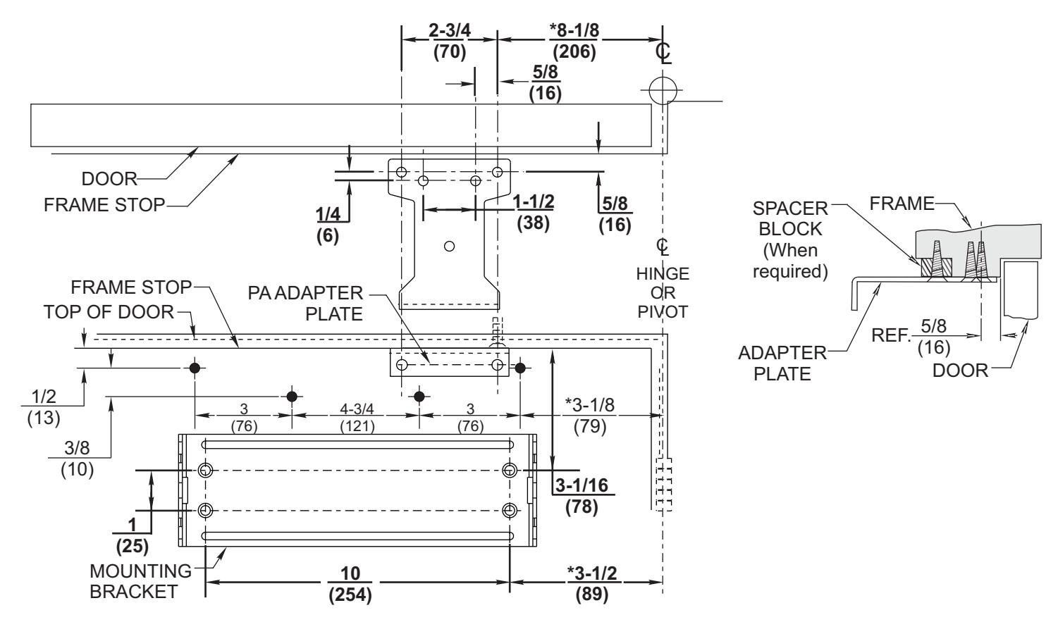
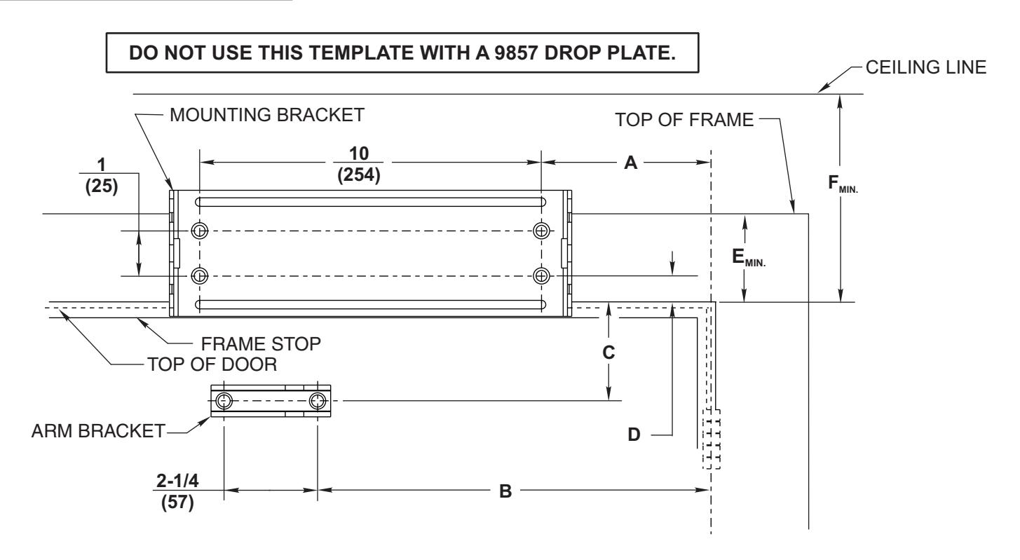
Regular Arm Template
If top rail is 3 (76) or greater " , use the template for the Closer Mounting Bracket provided. If top rail is 1-3/4 (45) to 2-15/16 (75), use 9586 Drop Plate Dimensions denoted by " .
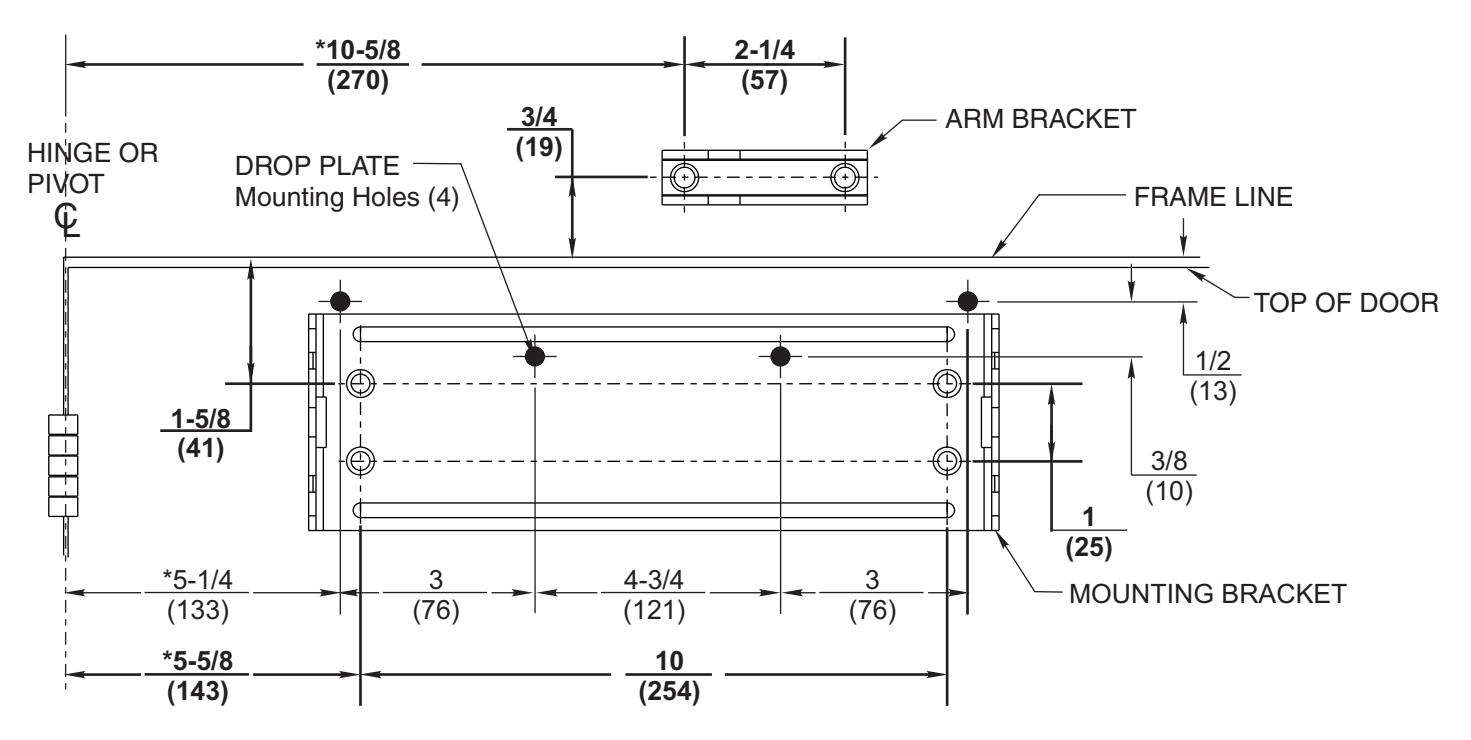
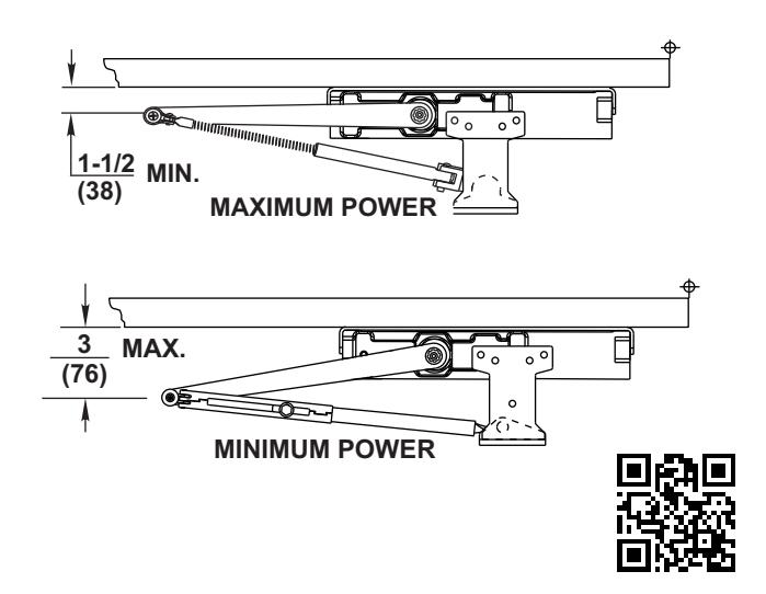
To obtain extra closing force add 3 (76) to dimensions marked. " This will limit degree of door opening to 110°. *
NOTES:
- Check hand of door, see page 2.
- Right Hand Application Shown. Left Hand Opposite.
- Dimensions given in inches (mm). Do Not Scale Drawing.
- Closer must be installed in a true horizontal plane to ensure proper closer performance.
- Door opening (up to 180°) is dependent upon door, frame, wall and hinge/pivot conditions permitting.
- Minimum clearance required over door:
Non-Hold Open: 1-1/2" (39) Hold Open: 1-11/16" (43)

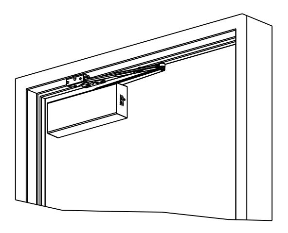
Regular Arm Installation Sequence
- • Select angle of opening and use dimensions shown in template and chart to locate 4 holes on door for Closer Mounting Bracket (or 4 holes for optional drop plate) and 2 holes on frame face for arm bracket. For applications that are different from above, a separate template will be supplied for door and frame preparation.
- Prepare door and frame for fasteners using "Preparation for Fasteners" chart, Figure 2, Page 4.
- Fasten Closer Mounting Bracket to door. Fasten optional drop plate to door, only if it is required for the door conditions.
- Install closer body with tube end away from hinge, with valves:
Down for Left Hand door UP for Right Hand door.
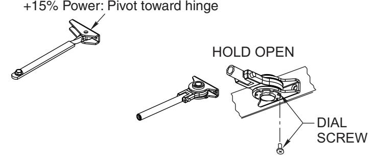
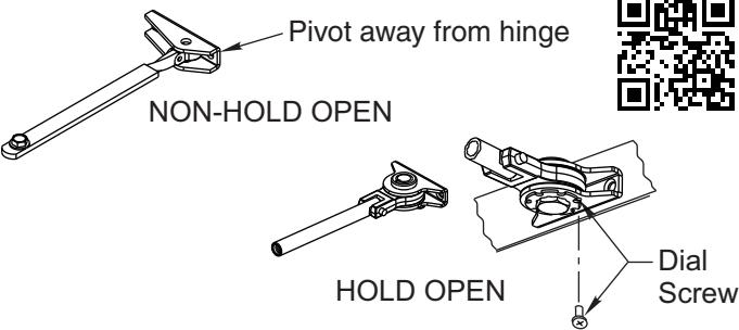
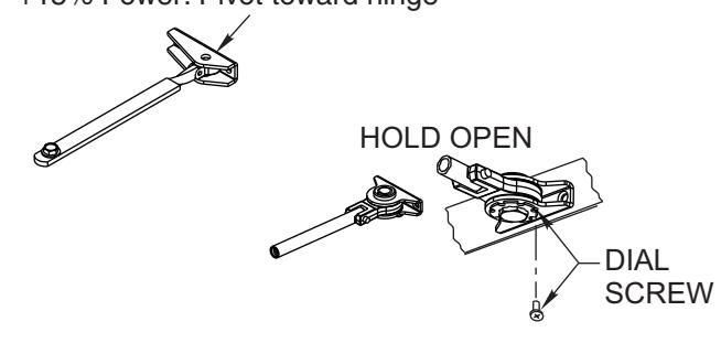
• Fasten arm bracket to frame. For standard non-hold open mounting, position with pivot point away from hinge. For additional 15% closing force, reposition arm mounting bracket so that pivot point is toward hinge. For hold open mounting, position so that dial screw is on UNDERSIDE of bracket.
Standard:Pivot away from hinge NON-HOLD OPEN
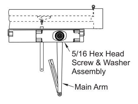
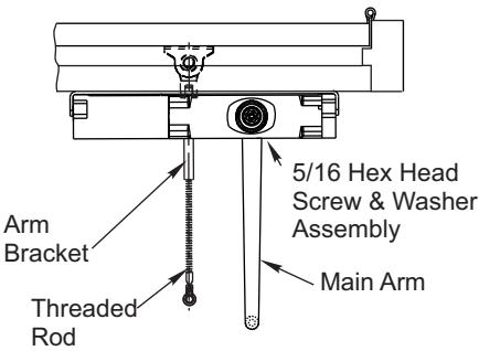
• Attach main arm to closer. For non-hold open mounting, main arm projects straight out at 90° angle to door. Install and tighten arm screw & washer assembly.
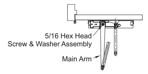
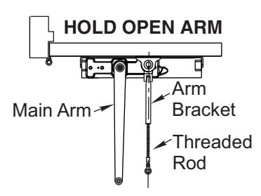
For hold open mounting, main arm projects straight out at 90° angle to door. Remove arm screw and washer from elbow joint and disassemble arm. Thread the rod into the arm bracket as shown below. Install and tighten arm screw & washer.
• Preload and adjust arm.
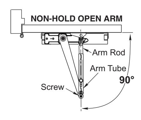
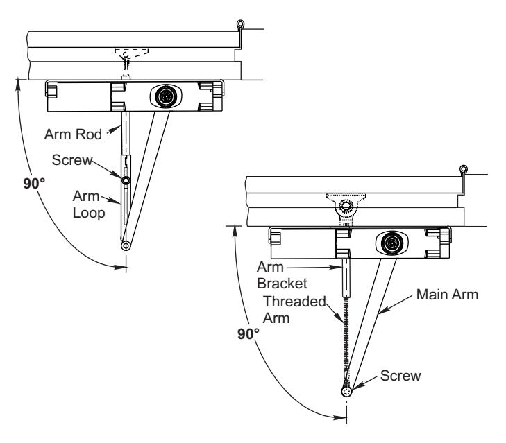
NON-HOLD OPEN ARM ONLY:
Open door and slide arm rod into arm loop. Close door, swing arms so adjusting arm is 90° to frame. With 7/16" wrench INSTALL and TIGHTEN SCREW SECURELY.
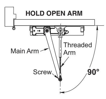
HOLD OPEN ARM ONLY:
While door is closed, adjust the threaded arm in the arm bracket until the bearing fits back onto the elbow joint on the main arm at 90° as shown below. RE-INSTALL AND TIGHTEN SCREW SECURELY.
• Make closer adjustments using information on page 11, then install closer cover.

Parallel Arm Template
If top rail is 5-1/4 (133) or greater, use the template for the Closer Mounting Bracket provided. If top rail is 1-3/4 (44) to 5-1/8 (130), use 9588 Drop Plate Dimensions denoted by +.
* To obtain extra closing force add 3" (77) to dimensions marked. This will limit degree of door opening to 110°.
NOTES:
- Check hand of door, see page 2.
- Right Hand Application Shown. Left Hand Opposite.
- Dimensions given in inches (mm). Do Not Scale Drawing.
- Closer must be installed mounted level to ensure proper closer performance.
- Door opening (up to 180°) is dependent upon door, frame, wall and hinge/pivot conditions permitting.

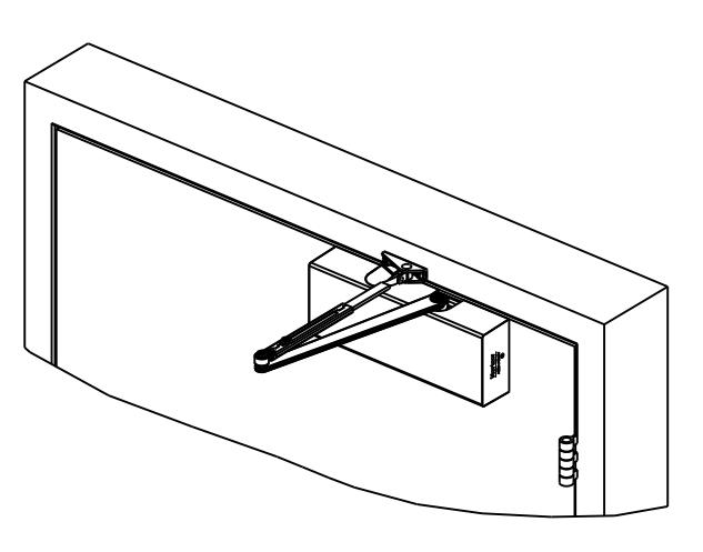
Parallel Arm Installation Sequence
- Select angle of opening and use dimensions shown in template to locate 4 holes on door for Closer Mounting Bracket (or 4 holes for optional drop plate) and 2 holes on jamb for adapter plate bracket. For applications that are different from above, a separate template will be supplied for door and frame preparation.
- Prepare door and frame for fasteners using "Preparation for Fasteners" chart, Figure 2, Page 4.
- Fasten Closer Mounting Bracket to door. Fasten optional drop plate to door, only if it is required for the door conditions.

- Fasten adapter plate bracket on jamb.
- Install closer body with tube end toward hinge, with valves:
Down for Left Hand door UP for Right Hand door.

• Mount arm bracket onto adapter plate bracket. For nonhold open mounting, position with pivot point away from hinge. For hold open mounting, position so that dial screw is facing DOWN.
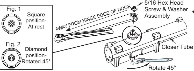
• Attach main arm to closer. Using hex wrench provided, turn closing speed and latching speed valves clockwise until completely closed. DO NOT OVER TIGHTEN. Using wrench, turn under side of spindle 45° toward the closer
tube until it reaches the diamond position (fig. 2 below). Immediately place arm on spindle so that it is parallel to the closer body. Install and tighten arm screw and washer assembly. Reopen valves.

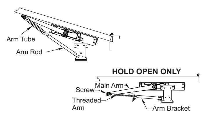
• Connect and position arms. Open door and slide arm rod into arm loop. Close door, swing arms so that they form a "V" position. With 7/16 wrench, " INSTALL AND TIGHTEN SCREW SECURELY. For hold open mounting, Remove main arm screw from elbow joint and disassemble arm. Thread the rod into the arm bracket as shown below. While door is closed, adjust the threaded arm in the arm bracket until the bearing fits back onto the elbow joint on the main arm and forms a "V" as shown below. RE-INSTALL AND TIGHTEN SCREW SECURELY.
• Power adjustment. To increase the power of the closer, readjust the arm so it is nearer the door. To decrease power, re-adjust the arm so it is farther away from the door and then secure screw in arm loop (non-hold open) or elbow joint (hold open).
• Make closer adjustments using information on page 11, then install closer cover.

Top Jamb Template
NOTES:
- Check hand of door, see page 2.
- Right Hand Application Shown. Left Hand Opposite.
- Dimensions given in inches (mm). Do Not Scale Drawing.
- Closer must be installed mounted level to ensure proper closer performance.
- All degrees of door opening are dependent upon door, frame, wall and hinge/pivot conditions permitting.
| OPENING MAXIMUM | Α | В | HINGE CONDITION |
|---|---|---|---|
| 110° |
6-7/8
(175) |
14
(356) |
|
| 140° |
5-1/8
(130) |
12-1/2
(318) |
Butts, Offset Pivots, and Swing Clear |
| 180° |
3-3/8
(86) |
10-1/2
(267) |
Hinges |
| 140° |
5-1/8
(130) |
12-3/8
(314) |
* CENTER
HUNG |
Dimensions "A" and "B" are taken from centerline of hinge as shown and apply to pivot point of swing clear hinges. Offset and center hung pivots.
|
HEADER
WIDTH |
С | D | E | F |
|---|---|---|---|---|
| STANDARD | 1-1/2 | 3/4 | 2-3/8 | 4 |
| STANDARD | (38) | (19) | (60) | (102) |
| NARROW | 1-7/8 | 3/8 | 1-3/4 | 3-1/2 |
| IVAINOVV | (48) | (10) | (45) | (89) |
* Must be single acting door.

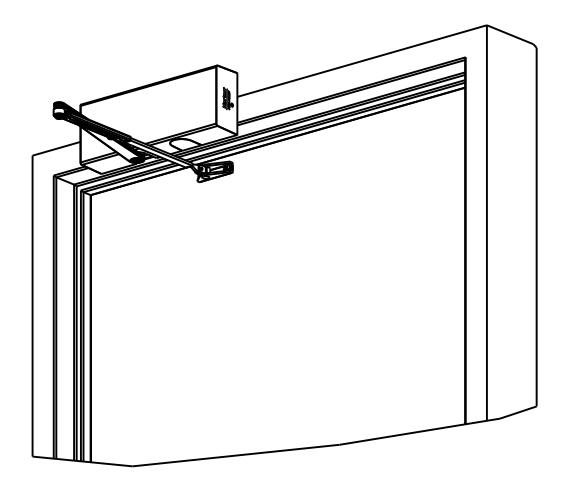
Top Jamb Installation Sequence
- Select angle of opening and use dimensions shown in template and chart to locate 4 holes on frame for Closer Mounting Bracket and 2 holes on door for adaptor plate. For applications that are different from above, a separate template will be supplied for door and frame preparation.
- Prepare door and frame for fasteners using "Preparation for Fasteners" chart, Figure 2, Page 4.
- Fasten Closer Mounting Bracket to jamb.
- Install closer body with tube end away from hinge, with valves:
Up for Left Hand door Down for Right Hand door.
• Fasten arm bracket to door. For standard non-hold open mounting, position with pivot point away from hinge. For additional 15% closing force, reposition arm mounting bracket so that pivot point is toward hinge. For hold open mounting, position so that dial screw is facing DOWN.
Standard:Pivot away from hinge +15% Power: Pivot toward hinge NON-HOLD OPEN
• Attach main arm to closer. For non-hold open mounting, main arm projects straight out at 90° angle to door. Install and tighten arm screw & washer assembly.
For hold open mounting, main arm projects straight out at 90° angle to door. Remove arm screw and washer from elbow joint and disassemble arm. Thread the rod into the arm bracket as shown below. Install and tighten arm screw & washer.
• Preload and adjust arm.
NON-HOLD OPEN ARM ONLY:
Open door and slide arm rod into arm loop. Close door, swing arms so adjusting arm is 90° to frame. With 7/16" wrench INSTALL and TIGHTEN SCREW SECURELY.
HOLD OPEN ARM ONLY:
While door is closed, adjust the threaded arm in the arm bracket until the bearing fits back onto the elbow joint on the main arm at 90° as shown below. RE-INSTALL AND TIGHTEN SCREW SECURELY.
• Make closer adjustments using information on page 11, then install closer cover.

Unit Adjustment

Spring Power Adjustment
Locate spring power adjuster from Illustration below
Size 1 thru 6 Adjustment See Chart
SPRING POWER ADJUSTMENT CHART
- All 9500 closers are factory set at an approximate Size 3.
- Adjust closer as necessary for door size using this chart.
- Readjustment may be required to suit prevailing conditions.
| Size of Door |
Spring Power Adjustment
No. Full Turns Clockwise |
||||
|---|---|---|---|---|---|
| Interior | Exterior | Exterior | Lquivalent | ||
|
In
Swing |
Out
Swing |
Regular & TJ Mounting |
Parallel Arm
Mounting |
(Approx.) | |
| 2 ' 4 " (712) | 2 ' 6" (764) | 1-5 | 2-7 | 3 | |
| 2 ' 6 '' (764) | 3 ' 0" (915) | 5-8 | 7-11 | 4 | |
| 3 ' 0 '' (915) | 3 ' 6" (1067) | 2 ' 6" (764) | 8-13 | 11-15 | 5 |
| 3 ' 6 '' (1067) | 4 ' 0" (1219) | 3 ' 0" (915) | 13-15 | 15-17 | 6 |
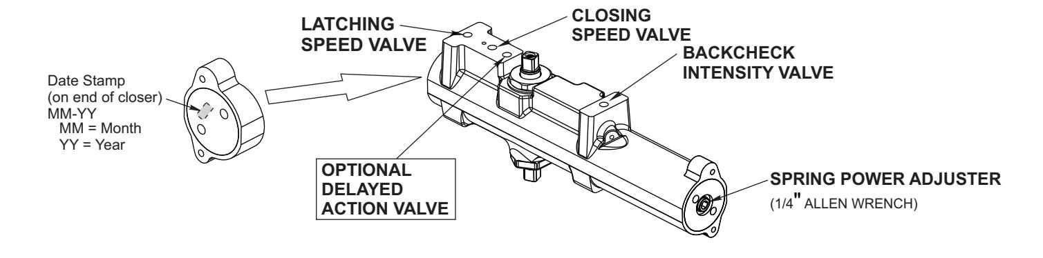

Closing Speed Valve (1/8 Allen Wrench Provided)
Factory preset for typical doors.
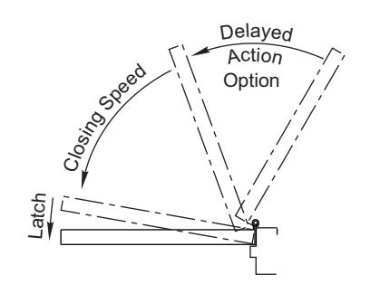
To adjust speed of door closing from fully open to a position 2" to 5" from closed, turn Closing Speed Valve CLOCKWISE to SLOW closing, COUNTER-CLOCKWISE to SPEED closing.
Latching Speed Valve (1/8 Allen Wrench Provided)
Factory preset for typical doors.
After closing speed has been obtained, turn latching speed valve CLOCKWISE to SLOW latching or COUNTER-CLOCKWISE to SPEED latching for last 2" to 5" of door travel.
NOTE: Set combination of CLOSING and LATCHING speeds to between 3 and 7 seconds Use of door by handicapped, elderly or small children may require even greater closing time.
Delayed Action Valve (1/8 Allen Wrench Provided)
Factory preset for typical doors.
Turn valve CLOCKWISE to SLOW closing, COUNTER-CLOCKWISE to SPEED closing. Delayed action may be adjusted from 20 seconds to 90 seconds, depending on degree of door swing. Delay occurs at the beginning of the door closing cycle from fully open down to 70°, where the closing speed valve then begins its control.
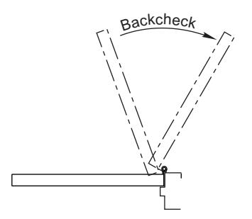
Backcheck Intensity Valve
Factory preset for typical doors.
Turn valve COUNTER-CLOCKWISE to reduce backcheck or CLOCKWISE to increase backcheck. (Backcheck should be set to give a soft cushioning action, not a sudden stop.)
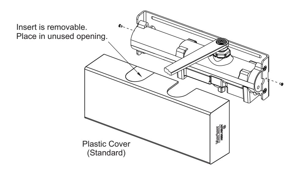
Installing Cover


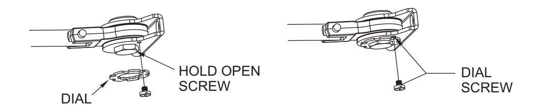
To Adjust Hold Open
Open the door to desired position and tighten the hold open screw firmly (For RH application, turn screw on underside CLOCKWISE. For LH application, turn screw COUNTER-CLOCKWISE.) Place the hold open dial over the hex head of the bracket screw so that one of the slots in the dial is directly over small screw hole tapped in bracket. Seat the dial tightly over the bracket. INSERT DIAL SCREW AND TIGHTEN SECURELY.