Norton 9500 Series Door Closer Slide Track Push or Pull Non-Hold Open or Hold Open Installation Instructions
Open the original PDF document
View PDF

9510 Series Installation Instructions
Slide Track Application (100° Maximum Door Swing) H.O. Bumper Stop
80-9395-9516-020 (08-13)
PUSH SIDE

IMPORTANT:
- An improperly installed or incorrectly adjusted door closer may cause property damage or personal injury; and will void product warranty.
- To avoid personal injury, DO NOT DISASSEMBLE THIS DOOR CLOSER BODY .
- Door closers must be securely fastened to a properly reinforced door and frame with fasteners provided.
- Door closers with the HOLD OPEN TRACK option are not permitted to be installed in fire door assemblies
BEFORE INSTALLING:

- The Americans with Disabilities Act (ADA) requires that doors having door closers have an opening force not to exceed 5 lbf.
- The door closer's power size adjustment feature may require adjustment to its lowest setting to comply with ADA opening force guidelines.
- ADA compliant closers are: 9530 & 9540.
| Size of Door & Door Closer | ||||||
|---|---|---|---|---|---|---|
|
Type
of Installation |
Interior |
Exterior
In-swinging |
Exterior
Out-swinging |
Recommended
Closer Size |
**Max.
Opening Force lbs/f |
|
|
PULL
SIDE Mounting |
2'6"
3'0" 3'6" 4'0" |
2'6"
3'0" 3'6" *4'0" |
1
2 3 4 5 |
8
14 16 22 24 26 |
||
|
PUSH
SIDE Mounting |
2'6"
3'0" 3'6" 4'0" |
2'6"
3'0" *3'6" *4'0" |
1
2 3 4 5 |
8
14 16 22 24 26 |
||
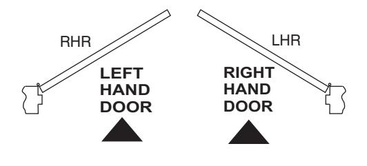
TO DETERMINE HAND OF YOUR DOOR:
** NOTE: These forces are for standard templating with bearing type hinges and do not account for pressure differentials and draft.


| Preparation for Fasteners | Figure 2 | ||
|---|---|---|---|
| Fasteners | Door or Frame | Drill-Sizes | |
| Standard |
Aluminum
or Metal |
No drill required | |
| #12-14 Self-Drilling Screw |
Wood
(see Note) |
3/16" (4.30 mm) | |
| 1/4" - 20 machine screw | Metal |
Drill: #7 (0.201" dia.)
Tap: 1/4" - 20 |
|
| Optional |
Hollow
Metal |
9/32" (7 mm) through;
3/8" (9.5 mm) door face opposite to closer |
|
|
Aluminum
or Wood |
3/8" (9.5 mm) through | ||
|
Through-bolts and
grommet-nuts |
All |
9/32" (7 mm);
3/8" (9.5 mm) dia. x 3/8" (9.5 mm) deep on door opposite to closer |
|
Note: Wood doors/frames: drill 1/8" (3.2) pilot hole when using Self-Drilling Screws.
Always consult door/frame manufacturer for fastener compatibility with the material of their door/frame.

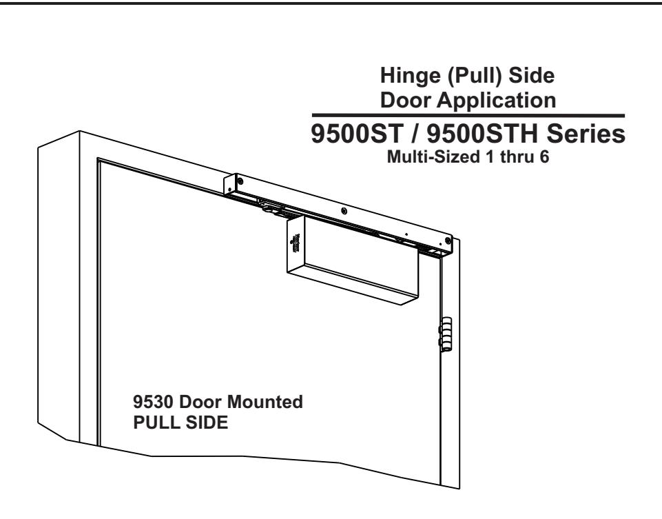
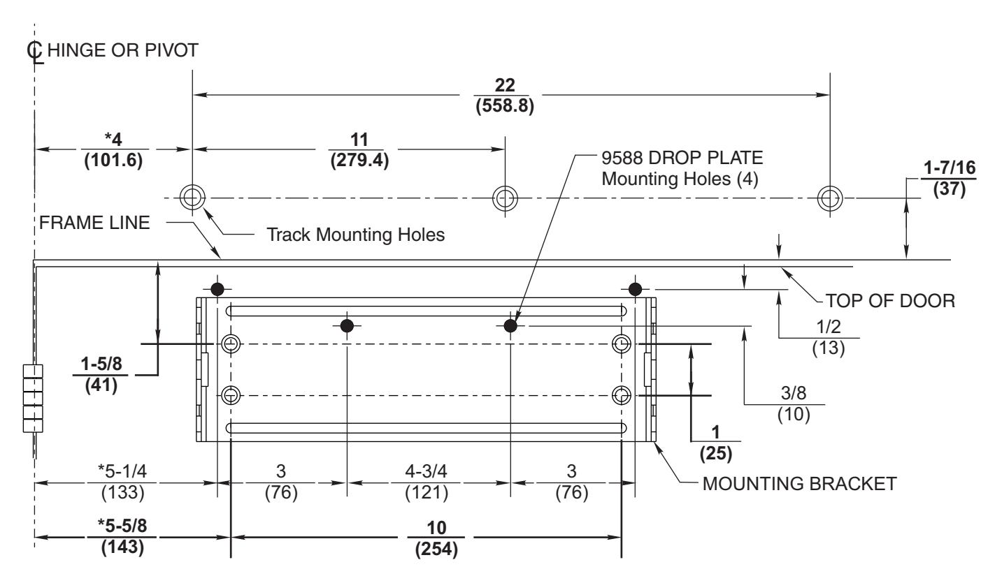
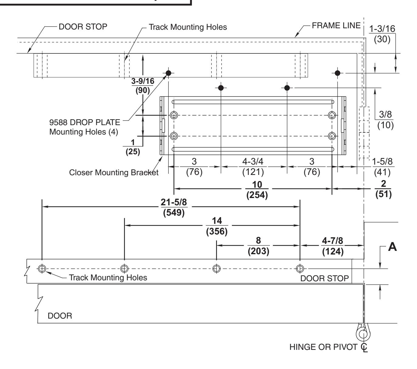
9530 Pull Side Track Template
- Door will travel additional 5° to dead stop.
- Door hold open position adjustable from 85° to 120° of door opening.
NOTES:
- Check hand of door, see page 2.
- Right Hand Application Shown. Left Hand Opposite.
- Dimensions given in inches (mm). Do Not Scale Drawing.
- Closer must be installed mounted level to ensure proper closer performance.
- Minimum clearance required over door: 2" (51).
- Minimum top rail: Without drop plate 3" (76), With drop plate 1-1/4" (32).

9530 Pull Side Track Installation Sequence
- Select angle of opening and use dimensions shown in template to locate 4 holes on door for Closer Mounting Bracket (or 4 holes for optional drop plate) and 3 holes on jamb for track.
- For applications that are different from above, a separate template will be supplied for door and frame preparation.
- Prepare door and frame for fasteners using "Preparation for Fasteners" chart, Figure 2, Page 4.
- Fasten Closer Mounting Bracket to door. Fasten optional drop plate to door, only if it is required for the door conditions.
- Install closer body with tube end away from hinge, with valves: Down for Left Hand door / UP for Right Hand door.
- Attach Track to Frame. With spring buffer toward hinge edge of frame and open side facing down, fasten track assembly to frame.
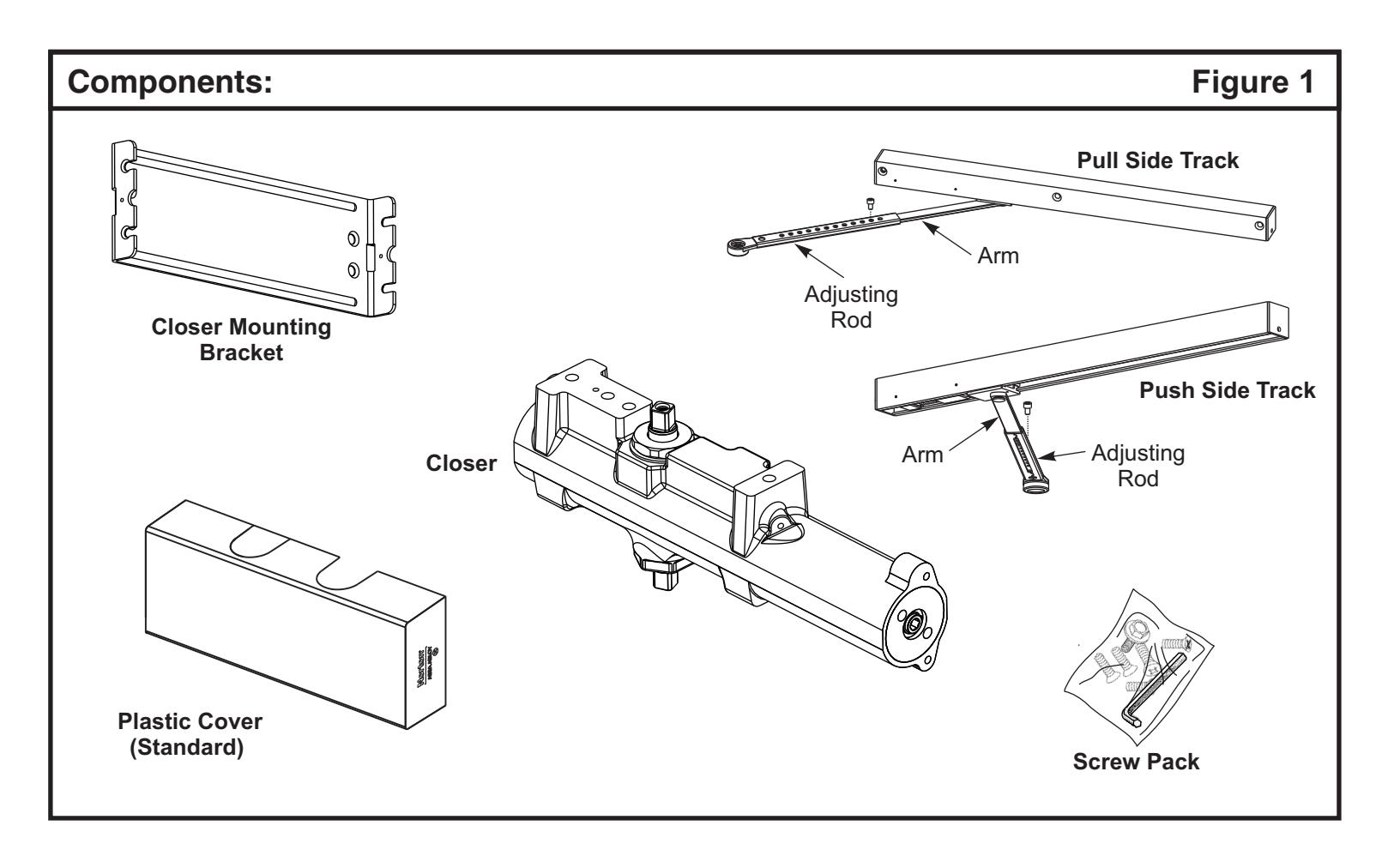
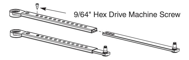
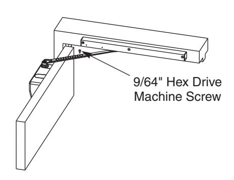
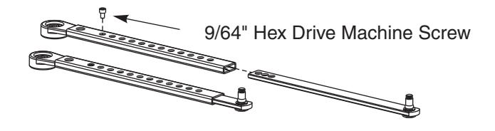
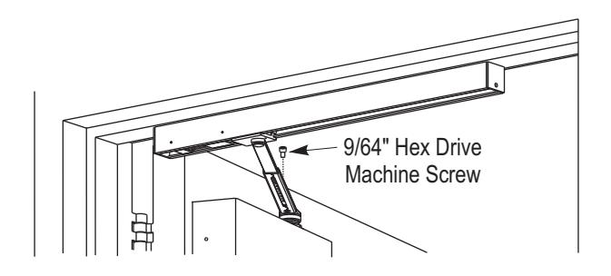
- Adjust Arm to Shortest Length. Install 9/64" hex drive socket head screw from screw pack to the arm's shortest length as shown.
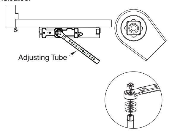
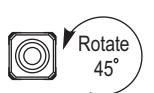
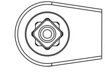
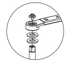
• Place Slide Arm on Pinion Shaft. Place the slide arm and two washers on the pinion shaft, indexed as shown below. Secure the arm with the arm screw and washer as indicated.
-
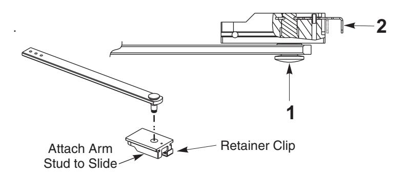
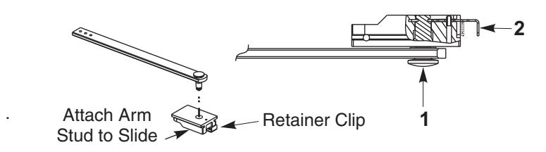
Insert Arm Stud into Slide Block
- 1) Insert the arm stud into the slide block in the track assembly.
- 2) Secure by pushing in on the retainer clip that extends from the slide block in the track, until it is flush with the slide block.
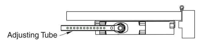
• Adjusting Door Opening / Hold Open Angle Open the door until the slider is against the cushioned stop or engaged in hold open (A1 Option only). Remove the 9/64" hex drive socket head screw from the arm. Open the door to the desired angle and install the hexdrive screw into the hole in the adjusting rod that is aligned with the hole in the adjusting tube.
• Make closer adjustments using information on page 9, then install closer cover. See Page 6 for ENGAGE/DISENGAGE Hold Open instructions.

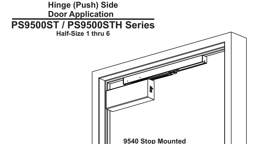
9540 Push Side Track Template
NOTES:
- Check hand of door, see page 2.
- Right Hand Application Shown. Left Hand Opposite.
- Dimensions given in inches (mm). Do Not Scale Drawing.
- Closer must be installed in a true horizontal plane to ensure proper closer performance.
- Minimum stop width: See Dimension A on the chart below.
- Minimum top rail: Without drop plate 5-1/2" (140), With drop plate 2-1/2" (64).
- Door will travel additional 5° to dead stop.
- Door hold open position adjustable from 85° to 110° of door opening.
Mount the Track CENTERED on the Stop with the following minimum distances from the door side of the stop.
|
A
Min |
|
|---|---|
| 1 (25) | 1-3/4 (45) |
| 3/4 (19) | 1-1/2 (38) |
Page 7

9540 Push Side Track Installation Sequence
-
Select angle of opening and use dimensions shown in template to locate 4 holes
on door for Closer Mounting Bracket (or 4 holes
for optional drop plate) and 4 holes on jamb for track.
- For applications that are different from above, a separate template will be supplied for door and frame preparation.
- Prepare door and frame for fasteners using "Preparation for Fasteners" chart, Figure 2, Page 4.
- Fasten Closer Mounting Bracket to door. Fasten optional drop plate to door, only if it is required for the door conditions
- Install closer body with tube end away from hinge, with valves: Down for Left Hand door / UP for Right Hand door.
- Attach Track to Frame. With spring buffer toward hinge edge of frame and open side facing down, fasten track assembly to frame.
- Adjust Arm to Shortest Length. Install 9/64" hex drive socket head screw from screw pack to the arm's shortest length as shown.
Place Slide Arm on Pinion Shaft. Continued at right, place the slide arm and two washers on the pinion shaft, indexed as shown at right. Secure the arm with the arm screw and washer as indicated.

-
· Insert Arm Stud into Slide Block
- 1) Insert the arm stud into the slide block in the track assembly.
- Secure by pushing in on the retainer clip that extends from the slide block in the track, until it is flush with the slide block.
Adjusting Door Opening / Hold Open Angle Open the door until the slider is against the cushioned stop or engaged in hold open.
Remove the 9/64" hex drive socket head screw from the arm. Open the door to the desired angle and install the hex-drive screw into the hole in the adjusting rod that is aligned with the hole in the adjusting tube.
Make closer adjustments using information on page 9, then install closer cover. See Page 10 for ENGAGE/DISENGAGE Hold Open instructions.

Unit Adjustment

Spring Power Adjustment
Locate spring power adjuster from Illustration below
Size 1 thru 6 Adjustment See Chart
SPRING POWER ADJUSTMENT CHART
- All 9500 closers are factory set at an approximate Size 3.
- Adjust closer as necessary for door size using this chart.
- Readjustment may be required to suit prevailing conditions.
| Size of D | Spring Power | ||||
|---|---|---|---|---|---|
| Interior |
Exterior
In Swing |
Exterior
Out Swing |
Adjustment
No. Full Turns Clockwise |
Equivalent
Closer Size (Approx.) |
|
| 2'4" (712) | 2 ' 6" (764) | 2-7 | 3 | ||
| 2 ' 6 '' (764) | 3 ' 0" (915) | 7-11 | 4 | ||
| 3 ' 0 '' (915) | 3 ' 6" (1067) | 2'6" (764) | 11-15 | 5 | |
| 3 ' 6 '' (1067) | 4 ' 0" (1219) | 3 ' 0" (915) | 15-17 | 6 | |
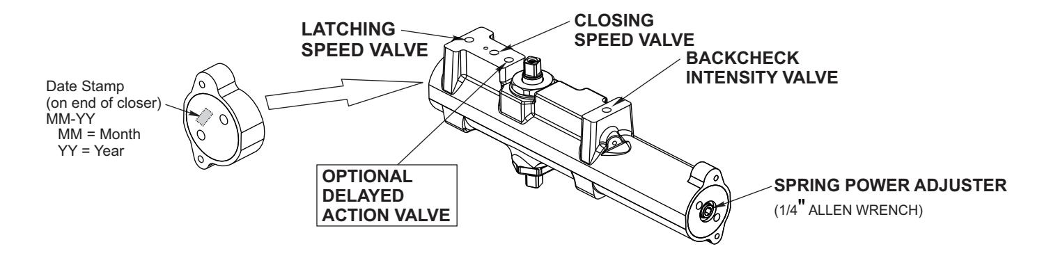

Closing Speed Valve (1/8 Allen Wrench Provided)
Factory preset for typical doors.
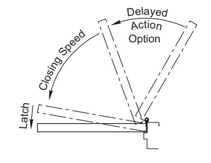
To adjust speed of door closing from fully open to a position 2" to 5" from closed, turn Closing Speed Valve CLOCKWISE to SLOW closing, COUNTER-CLOCKWISE to SPEED closing.
Latching Speed Valve (1/8 Allen Wrench Provided)
Factory preset for typical doors.
After closing speed has been obtained, turn latching speed valve CLOCKWISE to SLOW latching or COUNTER-CLOCKWISE to SPEED latching for last 2" to 5" of door travel.
NOTE: Set combination of CLOSING and LATCHING speeds to between 3 and 7 seconds Use of door by handicapped, elderly or small children may require even greater closing time.
Delayed Action Valve (1/8 Allen Wrench Provided)
Factory preset for typical doors.
Turn valve CLOCKWISE to SLOW closing, COUNTER-CLOCKWISE to SPEED closing. Delayed action may be adjusted from 20 seconds to 90 seconds, depending on degree of door swing. Delay occurs at the beginning of the door closing cycle from fully open down to 70°, where the closing speed valve then begins its control.
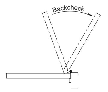
Backcheck Intensity Valve
Factory preset for typical doors.
Turn valve COUNTER-CLOCKWISE to reduce backcheck or CLOCKWISE to increase backcheck. (Backcheck should be set to give a soft cushioning action, not a sudden stop.)
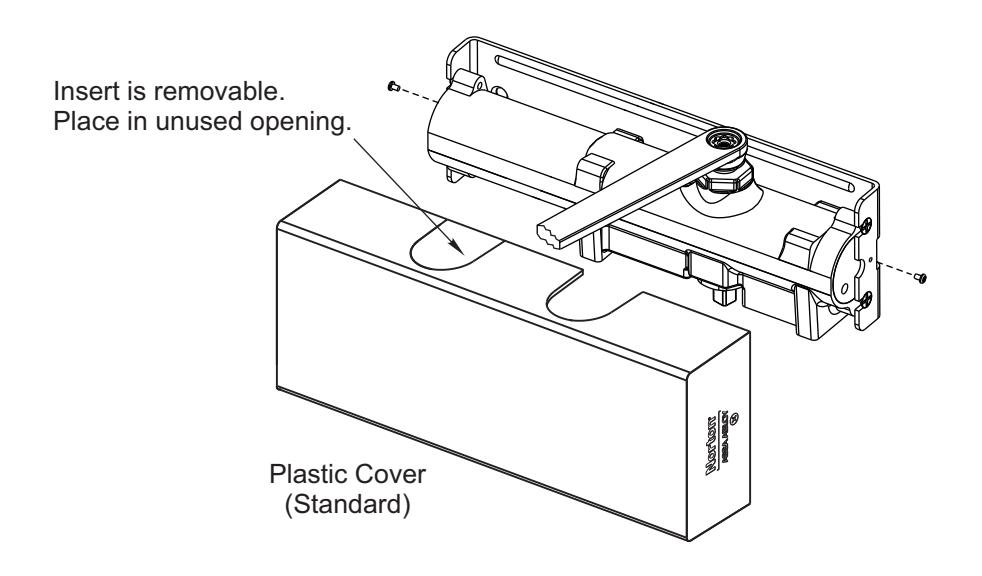
Installing Cover

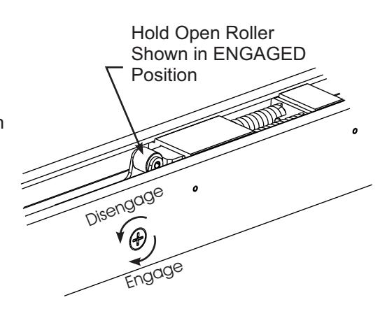
Engage/Disengage Hold Open
Hold Open Models Only: Turn Screw 1/2 Revolution to Engage / Disengage Hold Open.

3000 Highway 74 East • Monroe, NC 28112 Tel: (877)-974-2255 • Fax: (800)-338-0965 www.nortondoorcontrols.com