Norton 9500 Series Door Closer Regular Rigid Non-Hold Open Installation Instructions
Open the original PDF document
View PDF

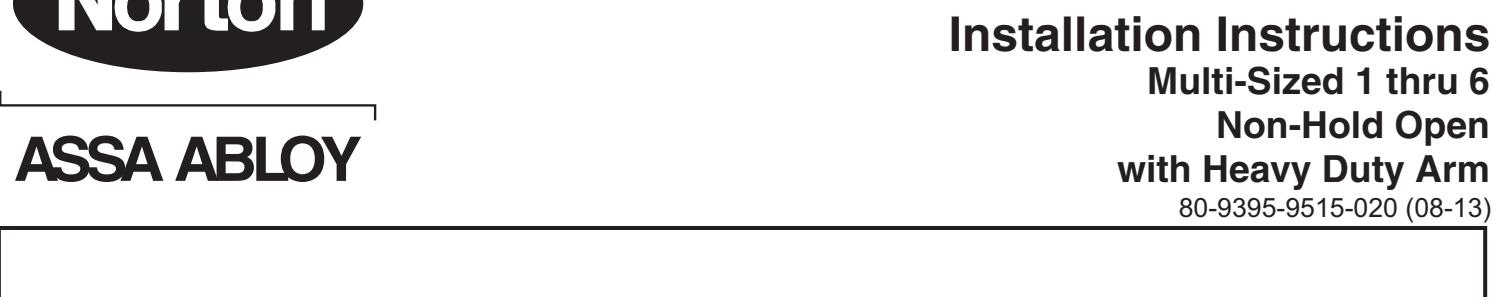
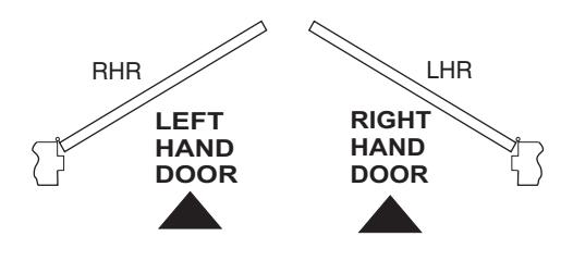
9510 Series Installation Instructions Multi-Sized 1 thru 6 Non-Hold Open with Heavy Duty Arm

IMPORTANT:
- An improperly installed or incorrectly adjusted door closer may cause property damage or personal injury; and will void product warranty.
- To avoid personal injury, DO NOT DISASSEMBLE THIS DOOR CLOSER BODY .
- Door closers must be securely fastened to a properly reinforced door and frame with fasteners provided.
BEFORE INSTALLING:

- The Americans with Disabilities Act (ADA) requires that doors having door closers have an opening force not to exceed 5 lbf. Use standard templating for regular arm and parallel arm applications. Jamb mounted applications use the template for 140° door opening to achieve the required opening force.
- The door closer's power size adjustment feature may require adjustment to its lowest setting to comply with ADA opening force guidelines.
- ADA compliant closers are: 9500.
| Size of Door & Door Closer | |||||||
|---|---|---|---|---|---|---|---|
|
Type
of Installation |
Interior |
Exterior
In-swinging |
Recommended
Closer Size |
**Max.
Opening Force Ibs/f |
|||
| 2'4" | 1 |
8
14 |
|||||
|
Regular
Arm |
3'0"
3'6" |
2'6" | 3 | 16 | |||
| 4'0" | 3'0" | 4 | 22 | ||||
| 4'6" | 3'6" | 5 | 24 | ||||
| 5'0" | *4'0" | 6 | 26 | ||||
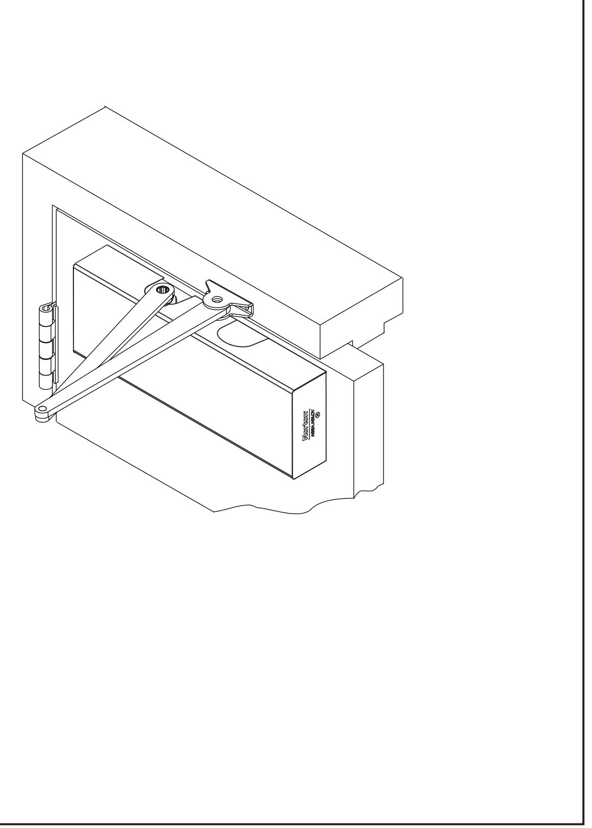
TO DETERMINE HAND OF YOUR DOOR:
** NOTE: These forces are for standard templating with bearing type hinges and do not account for pressure differentials and draft.


| Preparation for Fasteners | Figure 2 | |||
|---|---|---|---|---|
| Fasteners | Door or Frame | Drill-Sizes | ||
|
Aluminum
or Metal |
No drill required | |||
| Standard | #12-14 Self-Drilling Screw |
Wood
(see Note) |
3/16" (4.30 mm) | |
| 1/4" - 20 machine screw | Metal |
Drill: #7 (0.201" dia.)
Tap: 1/4" - 20 |
||
| Optional |
Hollow
Metal |
9/32" (7 mm) through;
3/8" (9.5 mm) door face opposite to closer |
||
|
Aluminum
or Wood |
3/8" (9.5 mm) through | |||
|
Through-bolts and
grommet-nuts |
All |
9/32" (7 mm);
3/8" (9.5 mm) dia. x 3/8" (9.5 mm) deep on door opposite to closer |
||
Note: Wood doors/frames: drill 1/8" (3.2) pilot hole when using Self-Drilling Screws.
Always consult door/frame manufacturer for fastener compatibility with the material of their door/frame.

HD Regular Arm Template
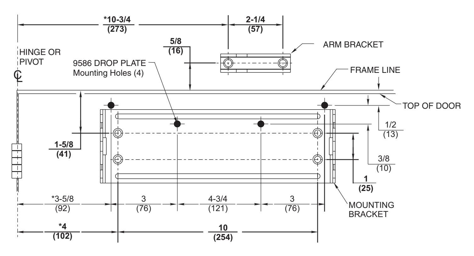
To obtain extra closing force add 3" (77) to dimensions marked. This will limit degree of door opening to 130°.
NOTES:
- Check hand of door, see page 2.
- Right Hand Application Shown. Left Hand Opposite.
- Dimensions given in inches (mm). Do Not Scale Drawing.
- Closer must be mounted level to ensure proper closer performance.
- Door opening (up to 180°) is dependent upon door, frame, wall and hinge/pivot conditions permitting.
- Maximum Hinge Side Reveal 1/8" (3).

HD Regular Arm Installation Sequence
- Select angle of opening and use dimensions shown in template to locate 4 holes on door for Closer Mounting Bracket (or 4 holes for optional drop plate) and 2 holes on jamb for arm bracket.
- For applications that are different from above, a separate template will be supplied for door and frame preparation.
- Prepare door and frame for fasteners using "Preparation for Fasteners" chart, Figure 2, Page 4.
- Fasten Closer Mounting Bracket to door. Fasten optional drop plate to door, only if it is required for the door conditions.
- Install closer body with tube end away from hinge, with valves: Down for Left Hand door / UP for Right Hand door.
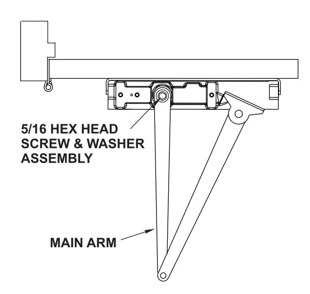
- Position arm on closer. Main arm projects straight out at 90° angle to door. Install and tighten 5/16 Hex Head Arm Screw & Washer assembly.
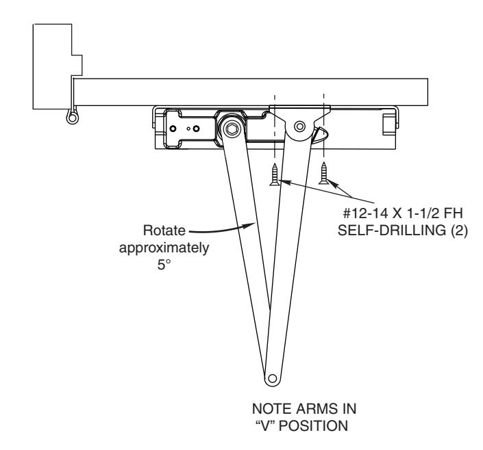
• Preload and fasten arm to frame. Close door, swing arms so that they form a "V" position. Align holes in arm bracket with pre-drilled holes on frame and install attaching screw.
• Make closer adjustments using information on page 7, then install closer cover.

Unit Adjustment

Spring Power Adjustment
Locate spring power adjuster from Illustration below
Size 1 thru 6 Adjustment See Chart
SPRING POWER ADJUSTMENT CHART
- All 9500 closers are factory set at an approximate Size 3.
- Adjust closer as necessary for door size using this chart.
- Readjustment may be required to suit prevailing conditions.
| Size of Door | Spring Power | |||
|---|---|---|---|---|
| Interior |
Exterior
In Swing |
Exterior
Out Swing |
Spring Power
Adjustment No. Full Turns Clockwise |
Equivalent
Closer Size (Approx.) |
| 2 ' 4" (712) | 2 ' 6" (764) | 1-5 | 3 | |
| 2 ' 6 '' (764) | 3 ' 0" (915) | 5-8 | 4 | |
| 3 ' 0 '' (915) | 3 ' 6" (1067) | 2 ' 6" (764) | 8-13 | 5 |
| 3 ' 6 '' (1067) | 4 ' 0" (1219) | 3 ' 0" (915) | 13-15 | 6 |
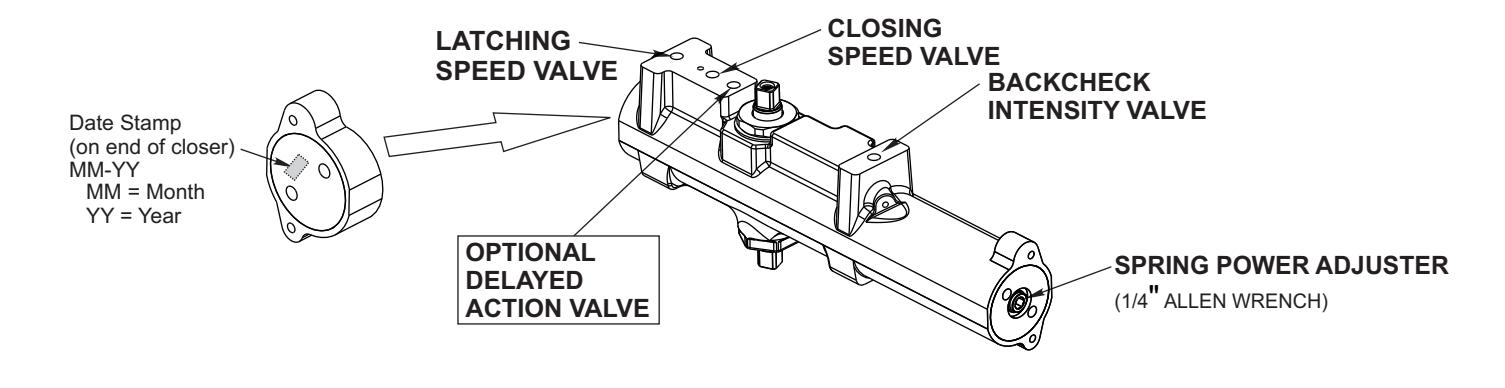

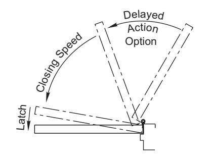
Closing Speed Valve (1/8 Allen Wrench Provided)
Factory preset for typical doors.
To adjust speed of door closing from fully open to a position 2" to 5" from closed, turn Closing Speed Valve CLOCKWISE to SLOW closing, COUNTER-CLOCKWISE to SPEED closing.
Latching Speed Valve (1/8 Allen Wrench Provided)
Factory preset for typical doors.
After closing speed has been obtained, turn latching speed valve CLOCKWISE to SLOW latching or COUNTER-CLOCKWISE to SPEED latching for last 2" to 5" of door travel.
NOTE: Set combination of CLOSING and LATCHING speeds to between 3 and 7 seconds Use of door by handicapped, elderly or small children may require even greater closing time.
Delayed Action Valve (1/8 Allen Wrench Provided)
Factory preset for typical doors.
Turn valve CLOCKWISE to SLOW closing, COUNTER-CLOCKWISE to SPEED closing. Delayed action may be adjusted from 20 seconds to 90 seconds, depending on degree of door swing. Delay occurs at the beginning of the door closing cycle from fully open down to 70°, where the closing speed valve then begins its control.
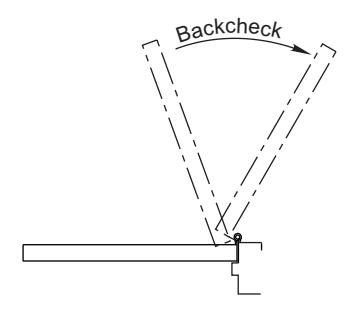
Backcheck Intensity Valve
Factory preset for typical doors.
Turn valve COUNTER-CLOCKWISE to reduce backcheck or CLOCKWISE to increase backcheck. (Backcheck should be set to give a soft cushioning action, not a sudden stop.)
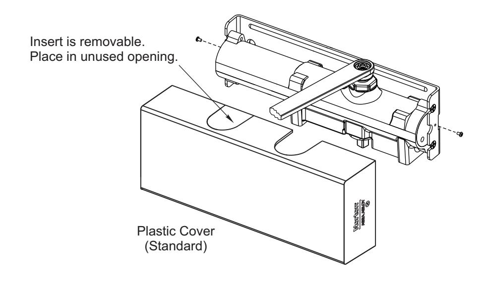
Installing Cover


ASSA ABLOY
3000 Highway 74 East • Monroe, NC 28112 Tel: (877)-974-2255 • Fax: (800)-338-0965 www.nortondoorcontrols.com