Norton 8000H Series Tri-Style Non-Handed Hold Open Door Closers 8100H 8300H 8500H 8301H 8501H Installation Instructions
Open the original PDF document
View PDF8000H
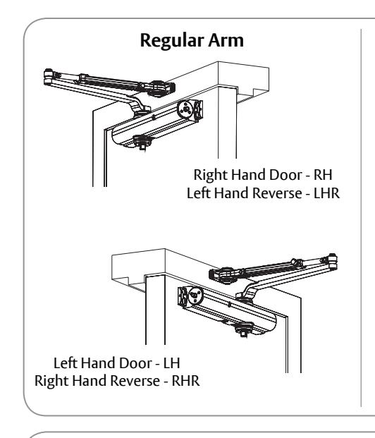
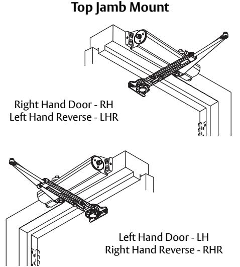
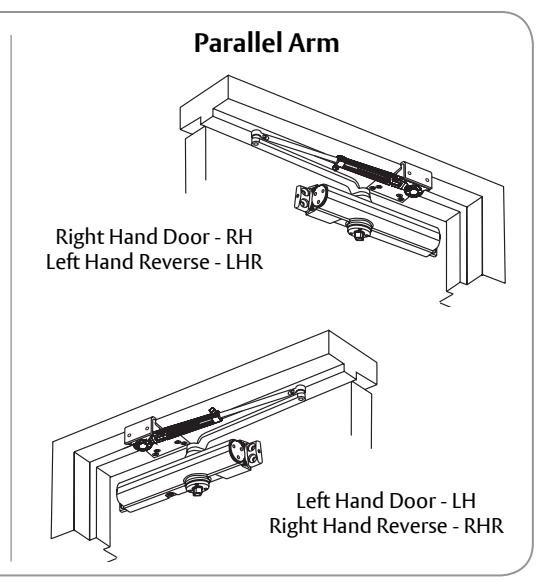
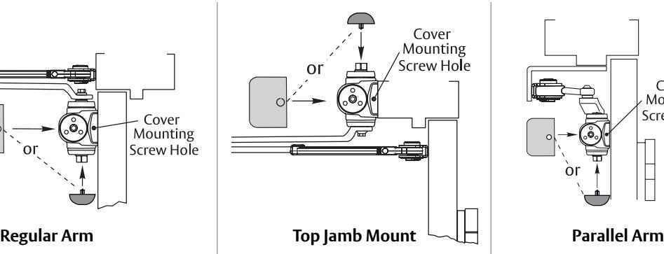
Non Handed Door Closer Regular Arm Top Jamb Mount Parallel Arm
With or without DA suffix (delayed action)
Hold Open Arm Models
Adjustable (Sizes 1-6) 8101H

ASSA ABLOY, the global leader in door opening solutions

WARNING
This product can expose you to lead which is known to the state of California to cause cancer and birth defects or other reproductive harm. For more information go to www.P65warnings.ca.gov.
Ce produit peut vous exposer au plomb qui, dans l'état de la Californie, est reconnu pour causer le cancer, des anomalies congénitales ou d'autres problèmes de reproduction. Pour plus d'informations, visitez: www.P65warnings.ca.gov.
Before You Begin
ATTENTION:
An incorrectly installed or improperly adjusted door closer can cause property damage or personal injury. These installation instructions should be followed to avoid the possibility of misapplication or misadjustment.
- "DA" suffix (Delayed Action) is an optional feature.
- For special applications, a separate door and frame preparation template is packed with these instructions. Use this instruction sheet for installation sequence and closer adjustments only.
- Doors should be hung on ball bearing or anti-friction hinges.
- A separate door stop is recommended.
- Always consult door/frame manufacturer for fastener compatibility.
- Door and frame must be properly reinforced.
- Adjust closing time speed between 3 and 7 seconds from 90° to 0°. Greater closing times may be required for elderly or handicapped.
- These door closers should NOT be installed on exposed side (weather side) of exterior doors.
- Dimensions are given in inches (millimeters).
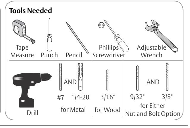
| Mounting Hardware | Door or Frame | Drill |
|---|---|---|
|
Closer, H/O Shoe or Optional PA Bracket:
1/4-14 x 1-1/2 Oval Flat Head Mach. Screw |
Wood
3/16" (4.76mm) |
|
|
Closer, H/O Shoe or Optional PA Bracket:
1/4-20 x 3/4 Oval Flat Head Mach. Screw |
Drill #7 (.201 dia. or 5.10mm) | |
|
H/O Shoe to Optional PA Bracket:
1/4-20 x 1/2 Oval Flat Head Mach. Screw |
Metal | Tap 1/4-20 |
|
Closer:
Sleeve Nut and Bolt (SNB) |
Hollow Metal |
9/32" (7.00mm) thru
3/8" (9.50mm) door face opposite to closer |
| (optional) | Aluminum or Wood | 3/8" (9.50mm) thru |
|
Closer:
Thru Bolt and Grommet Nut (TBGN) (optional) |
All |
9/32" (7.00mm) thru
3/8" (9.50mm) dia. x 3/8" (9.500mm) deep, door face opposite to closer |
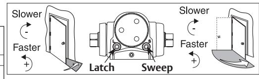
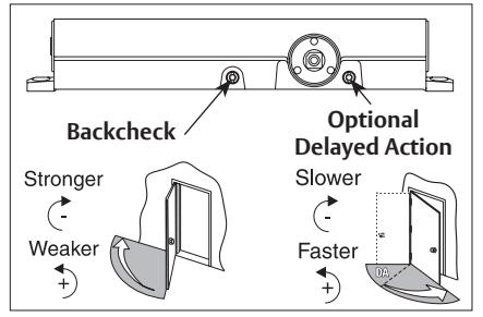
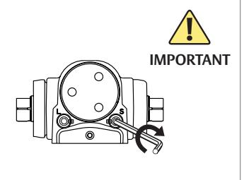
Closer Adjustments

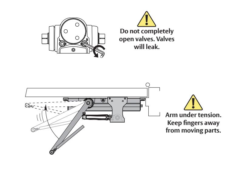
Use provided hex wrench to turn valves. NEVER force valves out of closer. NEVER completely close backcheck valve.
Door must be open to adjust spring closing power. Refer to chart. Do not use a power drill. Warranty will be void.
| Spring Closing Power |
Number of Turns
Required |
||||||
|---|---|---|---|---|---|---|---|
| Ä | TYPE | MAXIMUM DOOR SIZE | |||||
| DOOR |
OF
INST. |
* |
34"
(0.85M) |
36"
(0.90M) |
42"
(1.05M) |
48"
(1.20M) |
|
| 8500 | Regular Arm Top Jamb Parallel Arm | 5 | 8 | 11 | 13 | ||
| 8300, 8 | INTE | Parallel Arm | TUR | 7 | 10 | 13 | 16 |
| 0, 83 | EXTERIOR | Parallel Arm H Regular Arm Top Jamb Top Jamb Top Jamb Top Jamb Top Jamb | 7 | 10 | 13 | 16 | |
| 8100, | Parallel Arm | 9 | 12 | 15 | 18 | ||
| *20 | *20 FULL (360°) TURNS MAX. AVAILABLE = 10 TURNS AS SHIPPED | ||||||
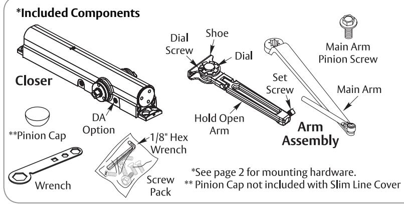
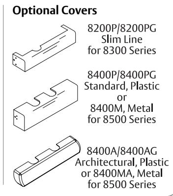
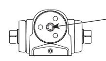
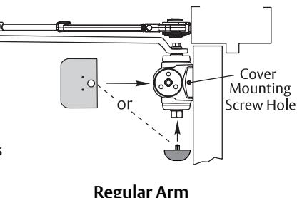
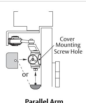
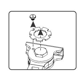
Pinion Cap and Cover

Do not over tighten cap or cover screws.
Architectural ("A") covers cannot be used on parallel mounted closers with doors swinging over 120°.

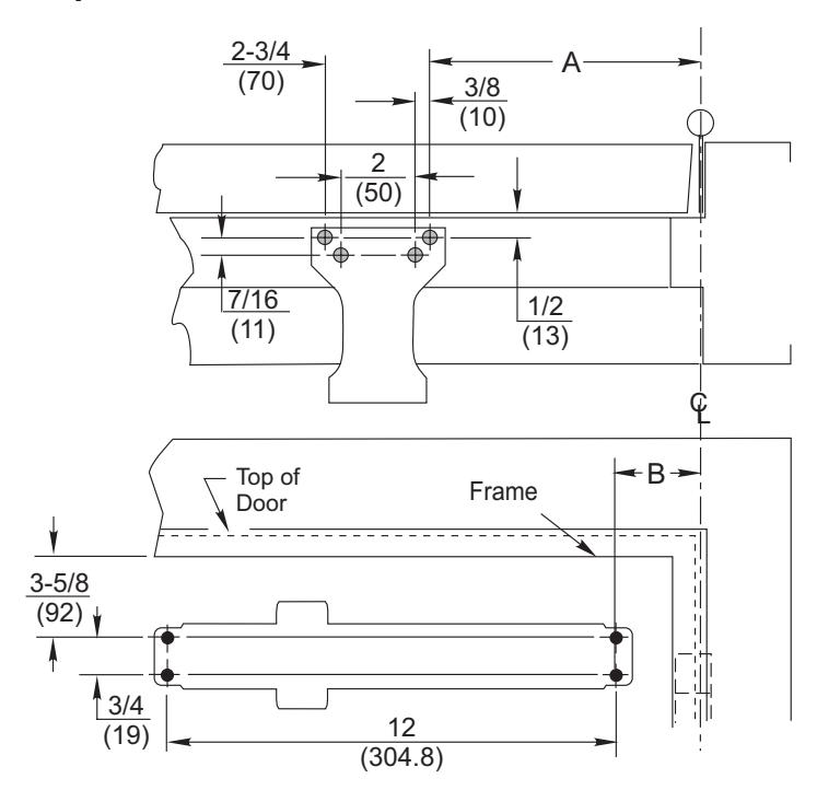
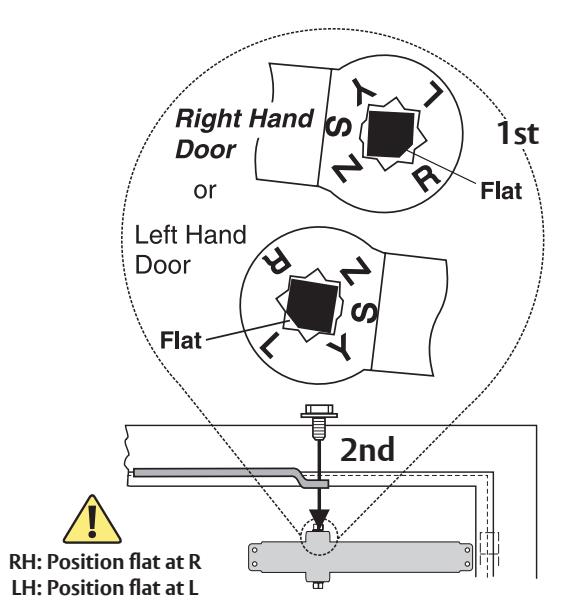
8000H Regular Arm Installation (Right Hand Shown)
1. Prepare door and frame.
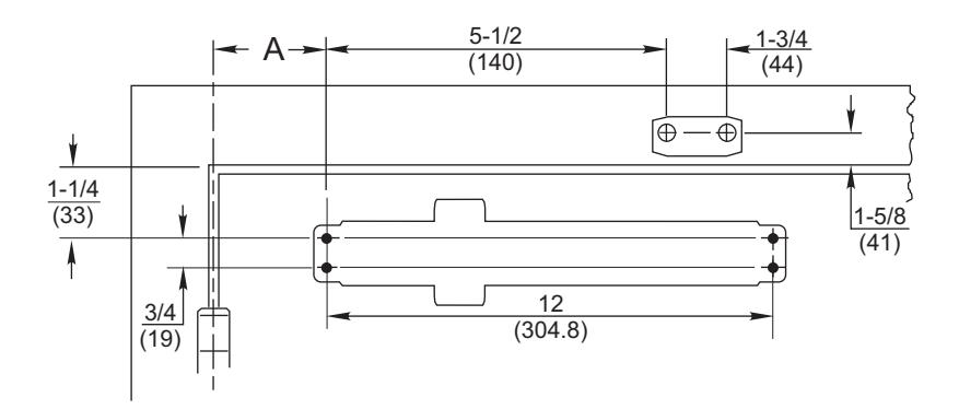
| Opening | Dimension "A" |
|---|---|
| To 100° |
7-1/2
(191) |
| 101° to 130° |
6
(152) |
| 131° to *180° |
4-1/2
(114) |
Door/Wall/Hardware/Jamb * conditions permitting
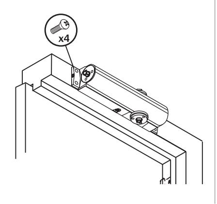
2. Mount closer to door. 3a. Remove dial from Hold Open arm.
3b. Install separate arms.
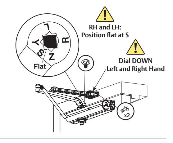
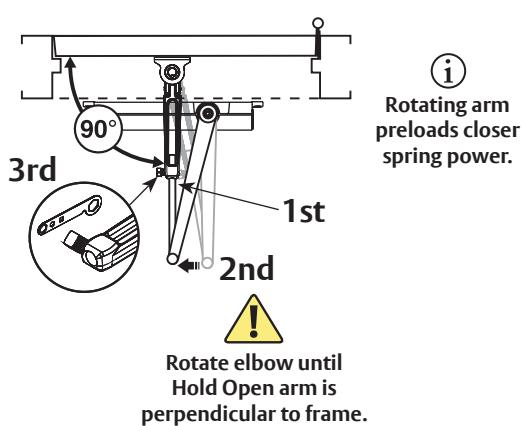
4. Connect arms, preload spring and tighten set screw.

You've installed the 8000H Hold Open Closer - Regular Arm.
Go to page 2 for closer adjustments and decorative cap or cover installation.

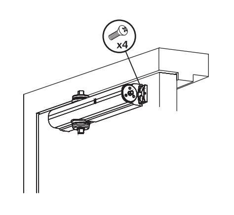
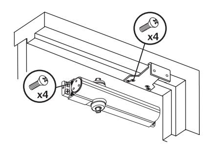
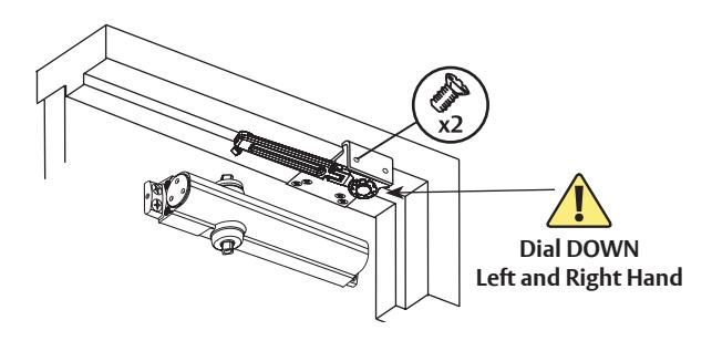
8000H Top Jamb Mount Installation (Right Hand Shown)
1. Prepare door and frame.
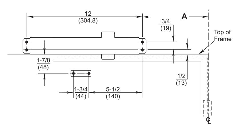
| Opening | Dimension "A" |
|---|---|
| To 100° |
7-1/2
(191) |
| 101° to 130° |
6
(152) |
| 131° to *180° |
4-1/2
(114) |
Door/Wall/Hardware/Jamb * conditions permitting
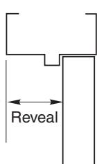
A longer connecting rod is required for reveals greater than 3" (76)
2. Mount closer to frame.
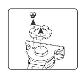
3a. Remove dial from Hold Open arm.
3b. Install separate arms.
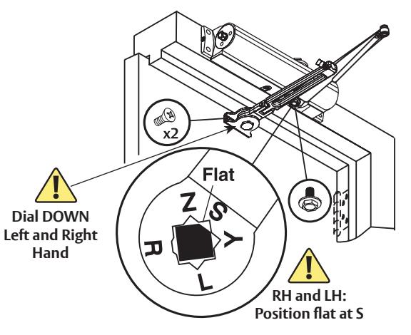
4. Connect arms, preload spring and tighten set screw.
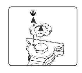
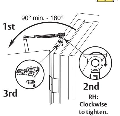
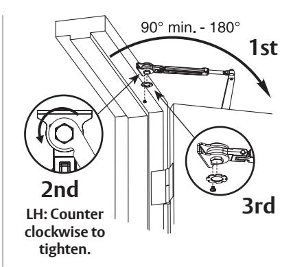
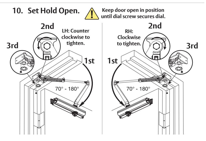
5. Set Hold Open.
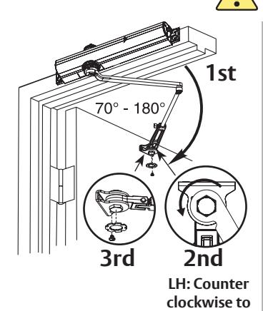
tighten.
Keep door open in position until dial screw secures dial.
to tighten.
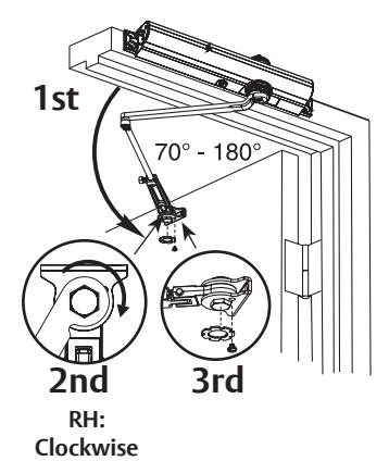
You've now installed the 8000H Hold Open Closer - Top Jamb Mount.
Go to page 2 for closer adjustments and decorative cap or cover installation.

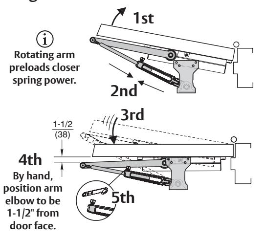
8000H Parallel Arm Installation (Right Hand Shown)
1. Prepare door and frame.
|
Door
Opening |
A | ВФ |
|---|---|---|
| To 120° |
9-1/2
(241) |
3-3/4
(95) |
| *121° to 180° |
7
(178) |
1-1/4
(32) |
* Door/Wall/Hardware/Jamb conditions permitting
2. Close latch and sweep valves.
3. Remove dial from Hold Open arm.
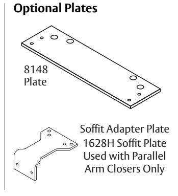
4. Install soffit plate and mount closer.
5. Install Hold Open arm to plate.
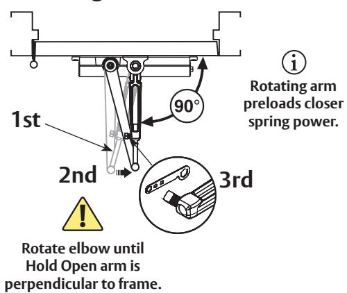
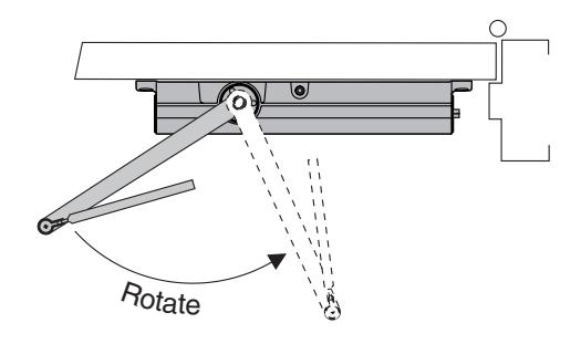
6. Place main arm on closer spindle and rotate.


8000H Parallel Arm Installation (Right Hand Shown) continued
7. Remove arm and attach as shown.
8. Open latch and sweep valves.
9. Connect arms, preload spring and tighten set screw.
You've now installed the 8000H Hold Open Closer - Parallel Arm.
Go to page 2 for closer adjustments and decorative cap or cover installation.
www.nortondoorcontrols.com
Norton Technical Product Support: Monroe, NC 28112 USA Phone: 800.438.1951 ext: 6030 TechSupport.Norton@assaabloy.com