Norton 8000 Series Door Closer Parallel Arm Door Controls UNI8000 Unitrol (Parallel) Arm Non-Hold Open or Hold Open Installation Instructions
Open the original PDF document
View PDF

Installation Instructions Parallel Arm Door Controls
An incorrectly installed or improperly adjusted door closer can cause property damage or personal injury. These instructions should be followed to avoid the possibility of misapplication or misadjustment.
2
Non Hold Open & Hold Open Models:
Series UNI-8300/UNI-8500
Available in sizes 2-3-4-5 or 6. Each power size can be increased by 50%.
Series UNI-8301/UNI-8501
Can be adjusted through a range of 1 through 6.
Standard Frame
"H" suffix indicates Hold Open Arm
"DA" suffix (Delayed Action) is an optional feature.
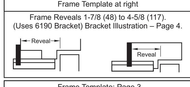
Installation 1-7/8 to 4-5/8 Frame Reveals (Uses 6190 Bracket). Bracket illustration page 4. Door and frame preparation See Page 2
Deep Frame Installation
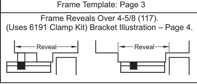
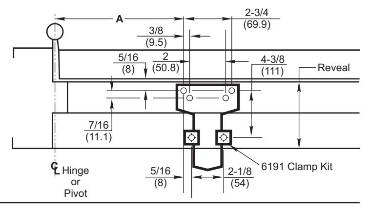
Frame Reveals Over 4-5/8 (Uses 6191 Clamp Kit). Bracket illustration page 4. Door preparation page 2 Frame preparation page 3
Flush Transom Installation
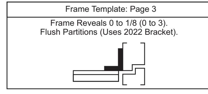
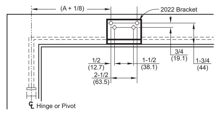
Flush Partitions (Uses 2022 Bracket). Bracket illustration page 4 Door preparation page 2 Frame preparation page 3

NOTE: For special applications a separate door and frame preparation template is packed with these instructions
Use this instruction sheet for installation sequence and closer adjustments only
- It is recommended that the door on which the door closer will be installed be hung on ball bearing hinges. Door must swing freely
- · Door and Frame must be properly reinforced, or use of special fasteners employed, to prevent the mounting screw from pulling out.
- · All dimensions are given in inches with corresponding metric dimensions (mm) in parenthesis.
Door Template Typical for All Installations Frame Template for 1-7/8 to 4-5/8 Reveals

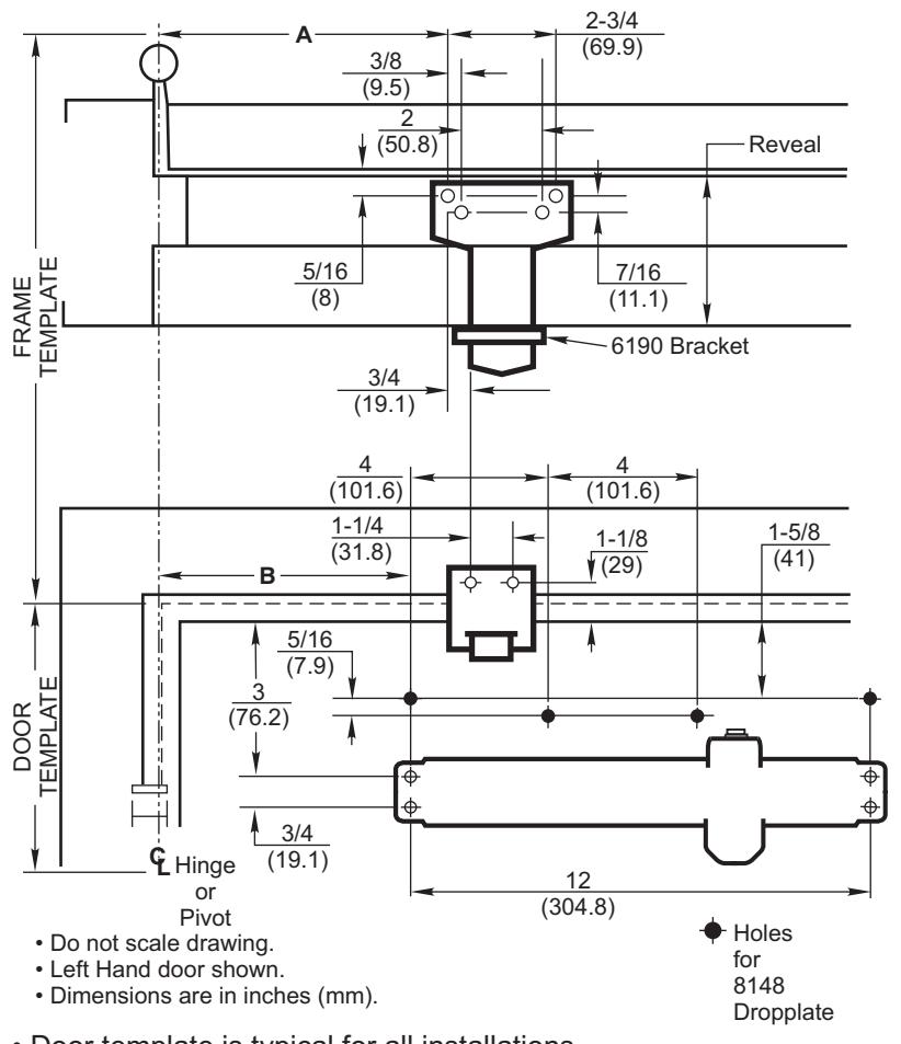
- Door template is typical for all installations.
- Frame template must be selected according to frame reveal:
| Inches | mm | Inches | mm | Inches | mm |
| 5/16 | 7.9 | 3-1/4 | 83 | 8-7/8 | 225 |
| 3/8 | 9.5 | 3-5/8 | 90 | 9-1/4 | 235 |
| 7/16 | 11.1 | 4 | 101.6 | 9-3/4 | 248 |
| 1/2 | 12.7 | 4-3/8 | 111 | 10-1/8 | 257 |
| 3/4 | 19.1 | 4-1/2 | 114 | 10-3/8 | 264 |
| 1-1/8 | 29 | 4-7/8 | 124 | 10-1/2 | 267 |
| 1-1/4 | 31.8 | 5-1/8 | 130 | 11 | 279 |
| 1-1/2 | 38.1 | 5-1/4 | 133 | 11-1/2 | 292 |
| 1-5/8 | 41 | 5-3/4 | 146 | 12 | 305 |
| 1-3/4 | 44 | 6-1/4 | 159 | 12-1/8 | 308 |
| 1-7/8 | 48 | 6-3/4 | 171 | 12-1/2 | 318 |
| 2 | 50.8 | 7-1/8 | 181 | 12-3/4 | 324 |
| 2-1/8 | 54 | 7-1/2 | 191 | 13-5/8 | 346 |
| 2-1/2 | 63.5 | 7-5/8 | 194 | 14-1/4 | 362 |
| 2-3/4 | 69.9 | 8-1/8 | 206 | 15-1/8 | 384 |
| 2-7/8 | 73 | 8-1/4 | 210 | ||
| 3 | 76 | 8-1/2 | 216 |
| Preparation for Fasteners | ||||||
|---|---|---|---|---|---|---|
| Fa | Fasteners | Drill-Sizes | ||||
| Self-Drilling Screw | Aluminum or Metal | No drill required | ||||
| Standard | Wood | 3/16" (4.30 mm) | ||||
| 1/4" - 20 machine screw | Metal |
Drill: #7 (0.201" dia.)
Tap: 1/4" - 20 |
||||
| Optional | Sleeve nuts and bolts |
Hollow
Metal |
9/32" (7 mm) through;
3/8" (9.5 mm) door face opposite to closer |
|||
|
Aluminum
or Wood |
3/8" (9.5 mm) through | |||||
| Through-bolts and grommet-nuts | All |
9/32" (7 mm);
3/8" (9.5 mm) dia. x 3/8" (9.5 mm) deep on door opposite to closer |
||||
| Dimensions for Doors 28" to 32" Wide | |||||||
|---|---|---|---|---|---|---|---|
| Opening | Dimension A | Dimension B | |||||
| Hold Open | Stop | Inches mm. Inches m | |||||
| 85° | 90° | 10-3/8 | 264 | 5-1/8 | 130 | ||
| 90° | 95° | 9-3/4 | 248 | 4-1/2 | 114 | ||
| 95° | 100° | 9-1/4 | 235 | 4 | 102 | ||
| 100° | 105° | 8-7/8 | 225 | 3-5/8 | 92 | ||
| 105° | 110° | 8-1/2 | 216 | 3-1/4 | 83 | ||
| 110° | 115° | 8-1/8 | 206 | 2-7/8 | 73 | ||
| Dimensions for Doors 33" to 41" Wide | |||||||
|---|---|---|---|---|---|---|---|
| Opening | Dimension A | Dimension B | |||||
| Hold Open | Stop | Inches mm. Inches mi | |||||
| 85° | 90° | 12-3/4 32 | 7-1/2 | 191 | |||
| 90° | 95° | 12 | 305 | 6-3/4 | 171 | ||
| 95° | 100° | 11-1/2 | 292 | 6-1/4 | 159 | ||
| 100° | 105° | 11 | 279 | 5-3/4 | 146 | ||
| 105° | 110° | 10-1/2 | 267 | 5-1/4 | 133 | ||
| 110° | 115° | 10-1/8 | 257 | 4-7/8 | 124 | ||
| Dimensions for Doors 42" to 48" Wide | ||||||
|---|---|---|---|---|---|---|
| Opening | Dimension A | Dimension B | ||||
| Hold Open | Stop | Inches mm. Inches m | ||||
| 85° | 90° | 15-1/8 384 9- | 9-3/4 | 248 | ||
| 90° | 95° | 14-1/4 | 362 | 8-7/8 | 225 | |
| 95° | 100° | 13-5/8 | 346 | 8-1/4 | 210 | |
| 100° | 105° | 13 | 330 | 7-5/8 | 194 | |
| 105° | 110° | 12-1/2 | 318 | 7-1/8 | 181 | |
| 110° | 115° | 12-1/8 | 308 | 6-3/4 | 171 | |
Frame Template for Reveals Over 4-5/8 Door Template on Page 2
Frame Template for Flush Partitions Door Template on Page 2
Installation Sequence
Read Front Page.
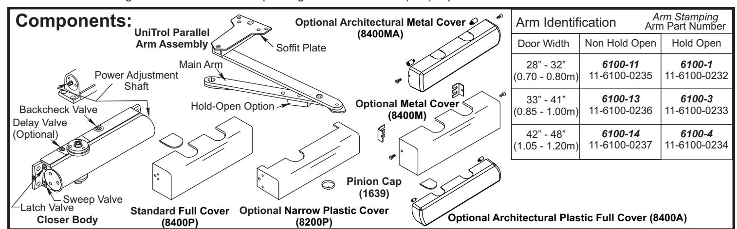
Installations and component identification are on this page. Arm assembly must be correct for width of door, see chart.
• Select Correct Door and Frame Template Combination.
Follow "Template Information" on Page 2 or Pages 2 and 3.
• Mark Location of Mounting Holes.
Use dimensions for hold-open or door stop angle desired. Mark position of 4 holes on door for closer (or drop plate) and 6 holes on frame for soffit plate (or 4 for 2022 angle bracket).
Prepare Holes for Fasteners.
See chart on Page 2.
Set closer average power.
For multi-size closers only, use "Power Setting-Multisize Closers" chart on page 4.
• Mount Closer to Door.
Dropplate first, if used. Place end with "S" and "L" valves toward the lock edge of the door. (Slip clips for optional full metal cover, 8400M, under closer feet, if this cover is used.)
Mount Arm to Frame.
Fasten soffit plate (or 2022 angle bracket if flush partition) to frame. Mount 6190 bracket or 6191 clamps to reinforce soffit plate. Or fasten 2022 bracket to frame and then soffit plate to 2022 bracket.

ASSA ABLOY
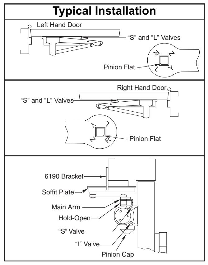
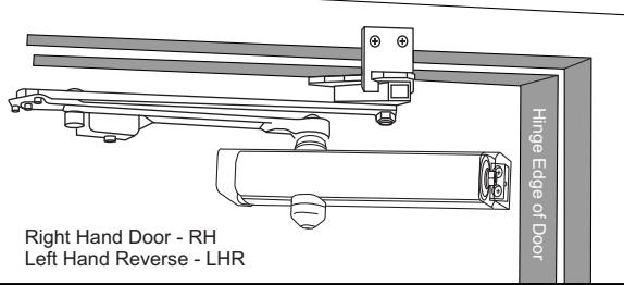
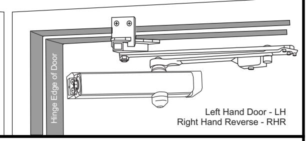
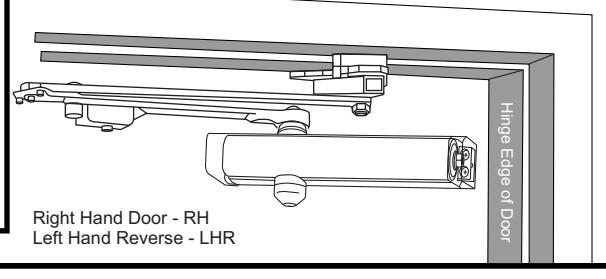
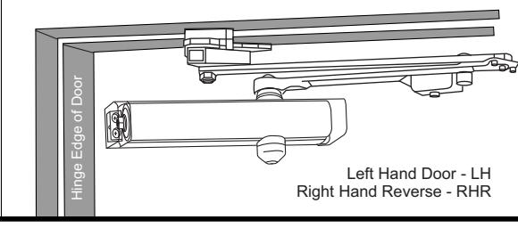
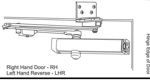
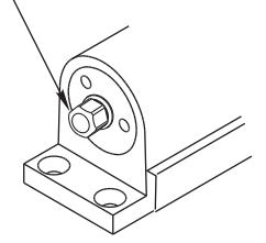
• Install Arm on Pinion Shaft.
Close valves "S" and "L". Rotate pinion over 45° to align main arm letter "R" (right hand) or "L" (left hand) with pinion flat. Fasten with arm screw. See "Typical Installation" figure above right. Re-open valves "S" and "L".
Adjust Closer.
See "Unit Adjustment" on Page 4.
Install Cover and Pinion Cap, if required.
8400 Full Cover: Slide cover insert into the un-used cutout in cover. Install cover using screws provided.
8200P Narrow Cover: Install cover using screws provided. Install pinion cap onto pinion shaft by hand or with a Phillips screw driver - DO NOT OVER TIGHTEN.
8400M Full Metal Cover: Fasten cover to mounting clips with screws provided.
8400MA Metal Architectural Cover: Remove cover insert where pinion is located. Install standoffs in ends of closer. Install cover using screws provided.
8400A Plastic Architectural Cover: Slide cover insert into the un-used cutout in cover. Install standoffs in ends of closer. Snap cover over standoffs.
NOTE: Architectural Covers CAN NOT be used for doors swinging over 120° using parallel mount.
Unit Adjustment
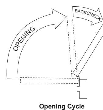
Opening Door Control
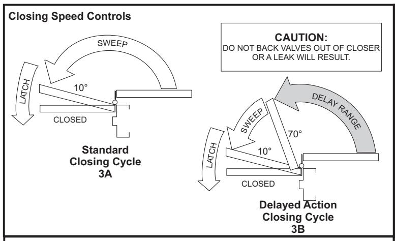
CAUTION:
DO NOT BACK VALVES OUT OF CLOSER OR A LEAK WILL RESULT.
NOTE: By law the Americans with Disabilities Act (ADA) may require that door closer installation comply with accessability guidelines.
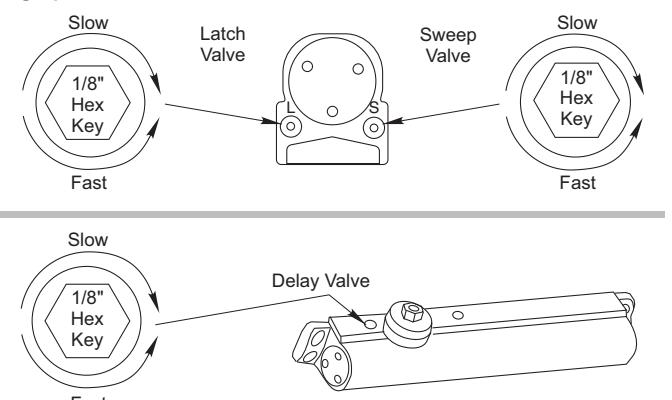
Closing Speed Controls
Backcheck Control
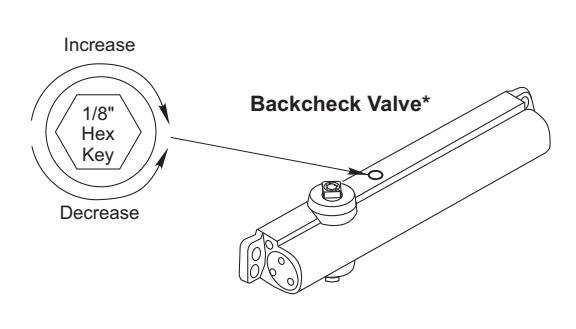
* NEVER close this valve completely.
Closing Power Control
Use 5/16" socket or adjustable wrench for adjustment.
To increase power turn Spring Adjustment Shaft clockwise. A total of 20 360° turns of the nut will provide maximum power.
Power Adjustment Chart (Multi Size Closers)
| • | , | ||||||
|---|---|---|---|---|---|---|---|
| PARALLEL ARM | MAXIMUM DOOR SIZE | ||||||
| DOOR | INSTALLATION | * | 28-32" | 33-41" | 42-48" | Max # | |
| (0.70-0.80 m) | (0.85-1.00 m) | (1.05-1.20 m) | of turns | ||||
| INT | UNI-8301/ |
360°
VS WER MENT FT |
7 | 10 | 16 | 20 | |
| EXT | UNI-8501 |
FULL:
TURI OF PO' ADJUST SHAI |
9 | 12 | 18 | 20 | |
*20 -360° TURNS MAXIMUM AVAILABLE
Door Holder Option
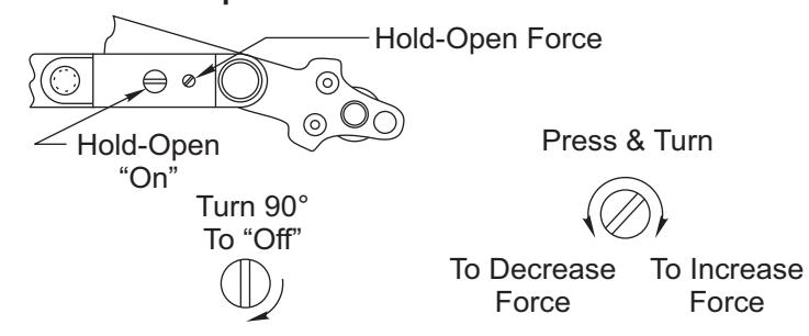
Hold-Open option is found at the arm elbow. To select holdopen "on" or hold-open "off" and to adjust the hold-open force ... use screwdriver as illustrated.
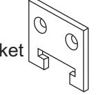
Bracket Illustrations
Standard 6190 Bracket
Deep Reveal Option
Spacer Block Clamps 2 Clamp Screws
4 Bracket
Screws
No. 6191 Reinforcing Kit
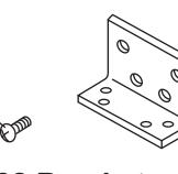
No. 2022 Bracket
Flush Partition Option

3000 Highway 74 East • Monroe, NC 28112 Tel: (877)-974-2255 • Fax: (800)-338-0965 www.nortondoorcontrols.com