Norton 7570 Series Door Closer CLP7570 CLP7770 CloserPlus Arm Non-Hold Open or Hold Open Installation Instructions
Open the original PDF document
View PDFInstallation Instructions
80-9377-0625-020 (03-13)
® CloserPlus Security Door Closer
An incorrectly installed or improperly adjusted door closer can cause property damage or personal injury. These instructions should be followed to avoid the possibility of CAUTION misapplication or misadjustment.
CAUTION
CLP7570/CLP7770 Series CPS7570/CPS7770 Series
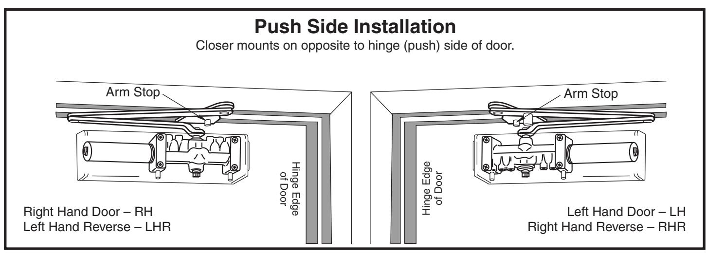
Parallel Non Hold Open or Hold Open Arm
Note: For Special Applications a separate door and frame preparation template is packed with these instructions. Use this instruction sheet for installation sequence and closer adjustments only.
For closers with or without "T" suffix Hold Open Control "T" indicates Thumbturn actuated hold open control.
| Series | |||
|---|---|---|---|
|
Sized*
Closer |
Multi-Sized **
Closer |
Product Type | |
| CLP7770 | CLP7570 |
Security Door Closer
(Door Closer with both a Security Cover and Security Arm) |
|
- * 7770 Series are sized door closers wi h 50% power increase capability. Power size 2 weakest power, power size 6 strongest. CLP t
- ** CLP7570 Series can be adjusted from power size 1 thru 6.
**Note:

- Ÿ Door closer cover is handed and cannot be reversed. All other components are non handed.
- Ÿ It is recommended that the door, on which the door closer will be installed, be hung on ball bearing hinges or offset pivots. Door must swing freely.
- Ÿ A separate door stop, supplied by others, is recommended to prevent damage to the door closer, closer arm, or to the door, frame or adjacent walls.
- Ÿ Door and Frame must be properly reinforced, or use of special fasteners employed, to prevent the mounting screws from pulling out.
- Ÿ All dimensions are given in inches with corresponding metric dimensions (mm) in parenthesis.
- Ÿ Torx tamper resistant drive machine screws are normally supplied with this product.
* For closers with or without "DA" suffix Delayed Action closing feature
Template
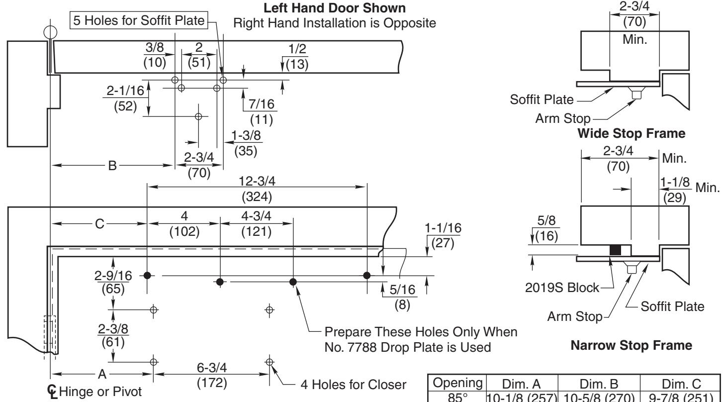
Do Not Scale Drawing Left Hand Door Shown Dimensions are in inches (mm). Maximum Door Swing 180°, conditions permitting.
| Opening | Dim. A | Dim. B | Dim. C | |
|---|---|---|---|---|
| 85° | 10-1/8 (257) | 10-5/8 (270) | 9-7/8 (251) | |
| 90° | 9-1/4 (235) | 9-3/4 (248) | 9 (229.6) | |
| 95° | 8-5/8 (219) | 9-1/8 (232) | 8-3/8 (213) | |
| 100° | 7-7/8 (200) | 8-3/8 (213) | 7-5/8 (194) | |
| 105° | 7-3/8 (187) | 7-7/8 (200) | 7-1/8 (181) | |
| 110° | 6-3/4 (171) | 7-1/4 (184) | 6-1/2 (165) | |
| Preparation for Fasteners | |||||||||
|---|---|---|---|---|---|---|---|---|---|
| Fasteners |
Door or
Frame |
Drill-Sizes | |||||||
| Standard |
1/4" - 20
Machine Screw |
Metal |
Drill: #7 (0.201" dia.)
Tap: 1/4" - 20 |
||||||
| Optional |
Sex Nuts and Bolts
(SNB) |
Hollow
Metal |
9/32" (7 mm); through
3/8" (9.5 mm) on door or transom-face opposite to closer |
||||||
|
Aluminum
or Wood |
3/8" (9.5 mm) through | ||||||||
• set closer power for door size using chart below. For CLP7570 and CPS7570 MODELS ONLY
| Power Adjustment Chart | ||||||||
|---|---|---|---|---|---|---|---|---|
| DOOR |
PARALLEL ARM
INSTALLATION |
* | MAXIMUM DOOR SIZE | |||||
|
32"
(0.81 m) |
36"
(0.9 m) |
42"
(1.1 m) |
48"
(1.2 m) |
|||||
| INT | CLP7570 |
TURNS FROM
ZERO |
0 | 3 | 5 | 8 | ||
| EXT | 4 | 6 | 8 | 12 | ||||
| INT | 0 | 2 | 5 | 8 | ||||
| EXT | CPS7570 | 2 | 5 | 8 | 11 | |||
| *16 -360° TURNS MAXIMUM AVAILABLE | ||||||||
Install closer per instructions with the proper pre-load applied to the arm then adjust spring power. The power adjustment will not work properly if the closer spring is not pre-loaded.
To increase power, use 11/16" wrench to turn power adjustment nut clockwise. To decrease power, turn nut counter clockwise.
DO NOT use a power drill or driver to turn adjustment nut. This will damage closer and void warranty. "Spring Power Adjustment Nut" + -
Page 2 80-9377-0625-020 (03-13)
Installation Sequence
- Ÿ Use template on page 2 to locate holes on door and frame: 4 on door for closer or drop plate. 5 on underside of frame stop for soffit plate.
- Ÿ Prepare door and frame for fasteners using chart on page 2.
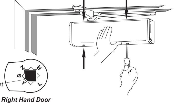
- Ÿ Mount closer on door. (A drop plate is available for use on doors having narrow top rails) Power Adjustment Nut should be away from hinge. Valves are DOWN for Left Hand Door . Valves are UP for Right Hand Door .
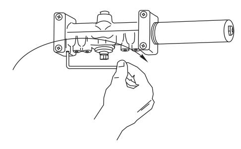
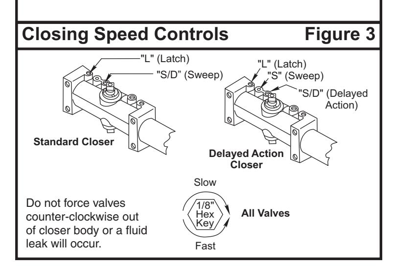
Ÿ Use 1/8" hex wrench to close valves. Turn Clockwise. For STANDARD CLOSER , close valves 'S/D' and 'L'. DELAYED ACTION CLOSER , close valves 'S' and 'L'.
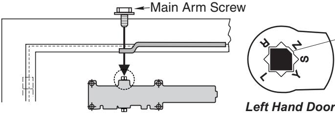
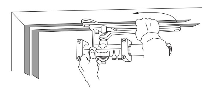
- Ÿ Set handing of "Arm Stop" on soffit plate. See illustration on Page 1 for positions. If required, rotate stop. Secure with 1/4-20 x 5/16 machine screw.
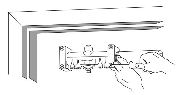
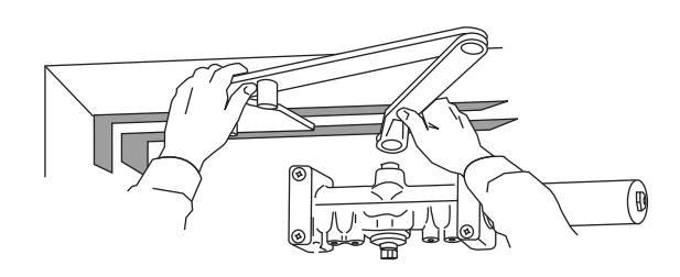
- Ÿ With door closed, use wrench to rotate pinion shaft as illustrated below.
- Ÿ Caution: Closer arm is under spring tension and may be difficult to rotate.
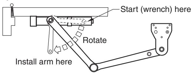
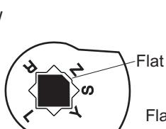
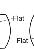
Ÿ Place main arm on shaft, aligning mark on arm with pinion flat on pinion shaft; "Z" for Left Hand Door; "Y" for Right Hand Door. Secure with 1/4-20 x 1/2 (13) with hex head machine screw.

CAUTION! DO NOT BACK VALVES OUT OF CLOSER OR A LEAK WILL RESULT
- Ÿ Reopen valves closed in Step 2. Turn Counterclockwise
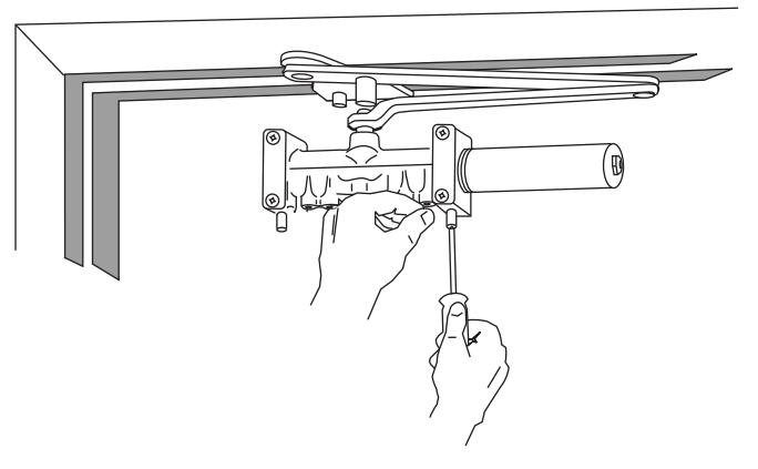
- Ÿ With door closed, align soffit plate with mounting holes in frame. Fasten soffit plate to frame with flat head screws provided.
- Ÿ Adjust closer per instructions on page 4 before installing cover.
Ÿ Install Cover: Screw Standoffs into holes in closer.
Ÿ Fasten cover to closer and cover bracket with 4 #8-32x1/4 round head screws provided.
Page 3 80-9377-0625-020 (03-13)
Unit Adjustment
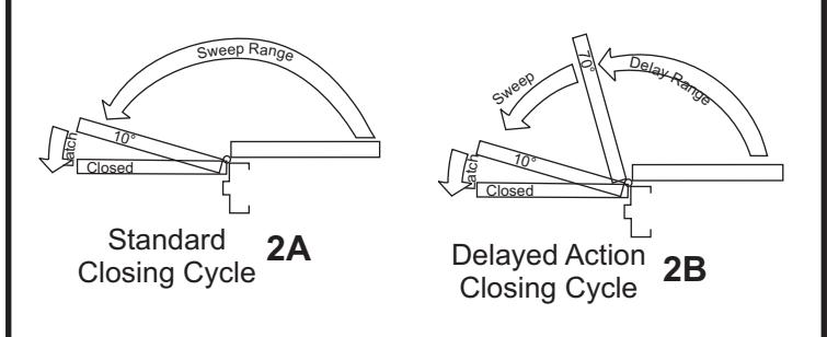
Closing Speed Controls (Figure 2A or 2B and 3.)
- Valve "S/D" Controls Sweep Range on Standard closer (or Delay Range on Delayed Action closer).
- Valve "L" Controls Latch Range.
- Valve "S" Controls Sweep Range only on Delayed Action closer.
Closing Power Control Figure 1 For CLP7570 and CPS7570 Only Set closer to desired size. For recommended sizes, refer to the Power Adjustment Chart on page 2. Install closer per instructions with the proper pre-load applied to the arm then adjust spring power. The power adjustment will not work properly if the closer spring is not pre-loaded. To increase power, use 11/16" wrench to turn power adjustment nut clockwise. To decrease power, turn nut counter clockwise. DO NOT use a power drill or driver to turn adjustment nut. This will damage closer and void warranty. Closing Speed Controls Figure 2
Norton® is a registered trademark of Yale Security Inc., an ASSA ABLOY Group company. Copyright © 2002, 2013, Yale Security Inc., an ASSA ABLOY Group company. All rights reserved. Reproduction in whole or in part without the express written permission of Yale Security Inc. is prohibited.
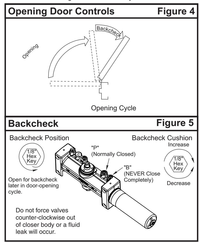
Opening Door Control (Figure 4.)
- Backcheck ("B") valve controls the hydraulic resistance to door opening. NEVER close this valve completely - it is not to provide a positive stop.
- Backcheck position ("P") valve controls the door angle where backcheck cushioning starts. Valve normally closed.
Door Holder Option
The Hold-Open feature is controlled by the hex knob located on the arm of the unit.
Thumbturn Adjustment (Units suffixed "T")
3000 Highway 74 East • Monroe, NC 28112 Tel: (877)-974-2255 • Fax: (800)-338-0965 www.nortondoorcontrols.com
80-9377-0625-020 (03-13) Page 4