Norton 7500 Series Door Closer 7540STH 7740STH Slide Track Push or Pull Hold Open Installation Instructions
Open the original PDF document
View PDF

Installation Instructions
Series 7540STH, 7740STH (Pull Side Mounted) Series PS7540STH, PS7740STH (Push Side Mounted) Door Closers with Slide Track Installations
- With or without "DA" suffix, delayed action closing feature.
- With or without "M" suffix, Metal Cover.
Hold Open Models
CAUTION
An incorrectly installed or improperly adjusted door closer can cause property damage or personal injury. These instructions should be followed to avoid the possibility of misapplication or misadjustment.
Note:
For Special Applications a separate door and frame preparation template is packed with these instructions. Use this sheet for installation sequence and closer adjustments only.
- •Sized Door Closers 7740 have 50% power increase capability. Closer size 2 has the weakest power, closer size 6 has the strongest power.
- •Multi-Sized Closer 7540 can be adjusted from size 1 thru 6.
For Use on Doors with 4½" or 5" Wide Butt Hinges
- Maximum pull side frame reveal is 1/8" (3mm).
- Minimum frame face for pull side is 1-1/8" (26.6mm).
- All components are non handed.
- The use of ball bearing hinges is recommended for the door on which the closer will be installed. Door must swing freely.
- Where severe or abusive conditions are expected a separate door stop, supplied by others, is recommended to assist in preventing damage to the door closer, closer arm; or to the door, frame or adjacent walls.
- Door and frame must be properly reinforced, or the use of special fasteners employed, to prevent door collapse or the mounting screws from pulling out.
- · All dimensions are given in inches with corresponding metric dimensions (millimeters) in parentheses.
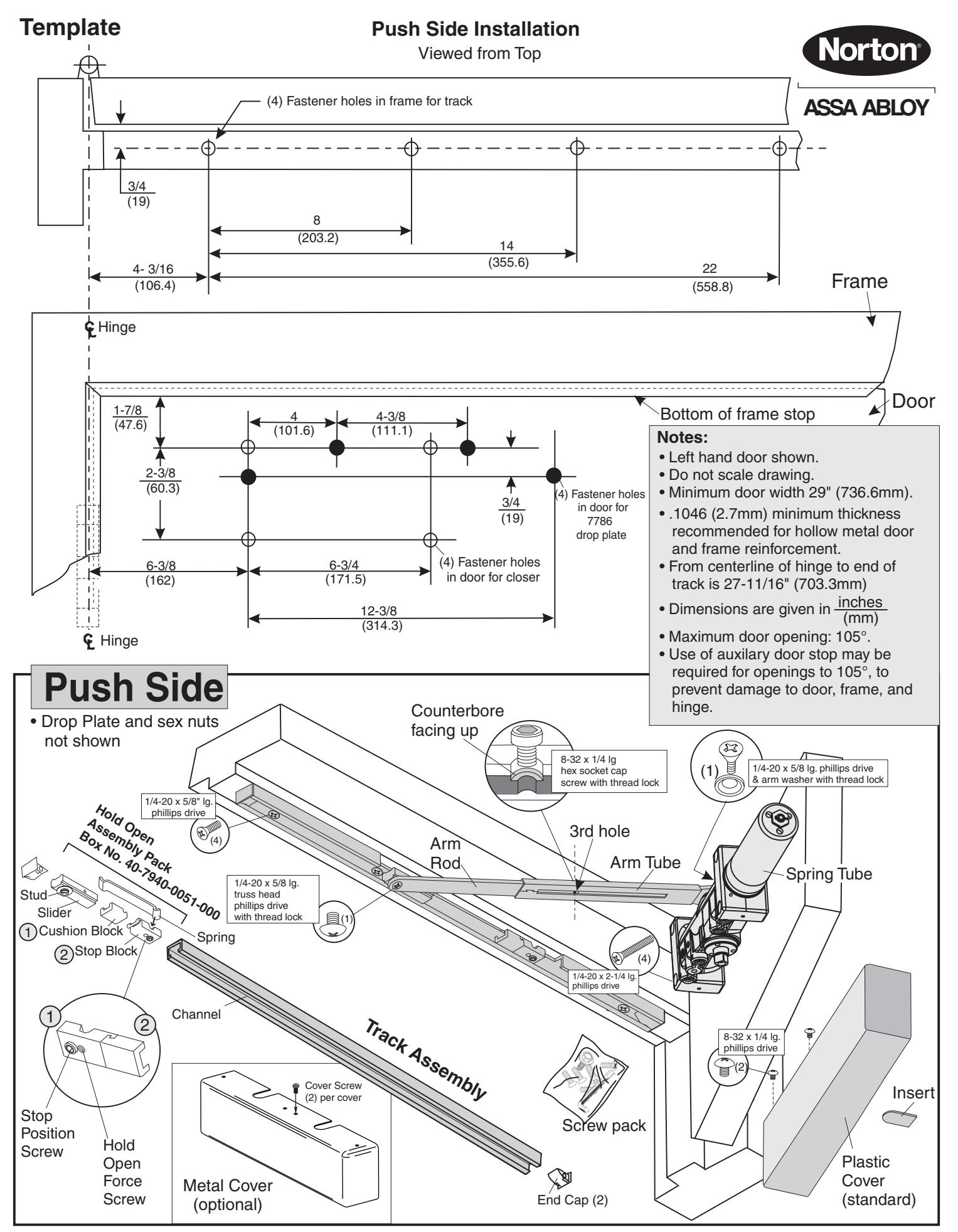
Installation Sequence Pull or Push Side Mount

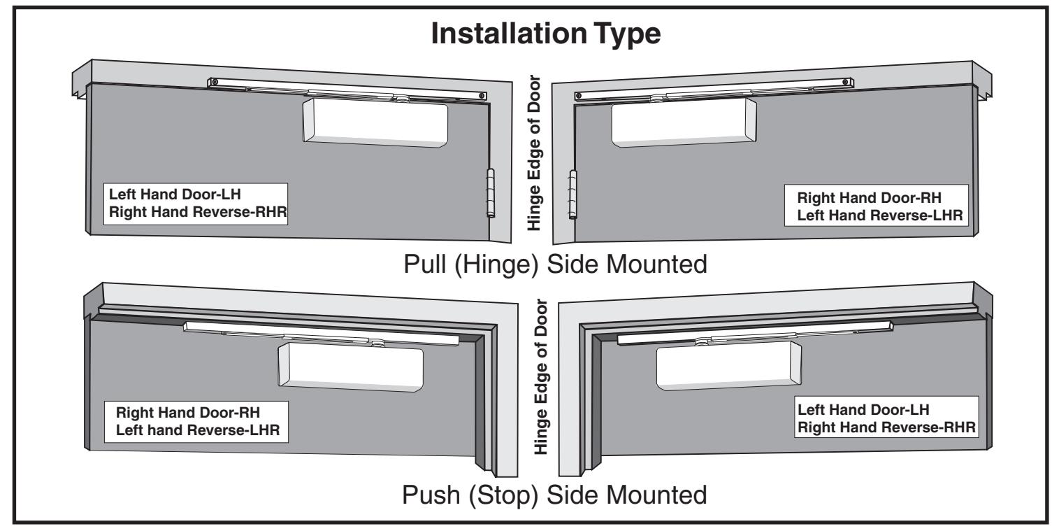
- Determine hand of door and type of installation from illustrations on page 1.
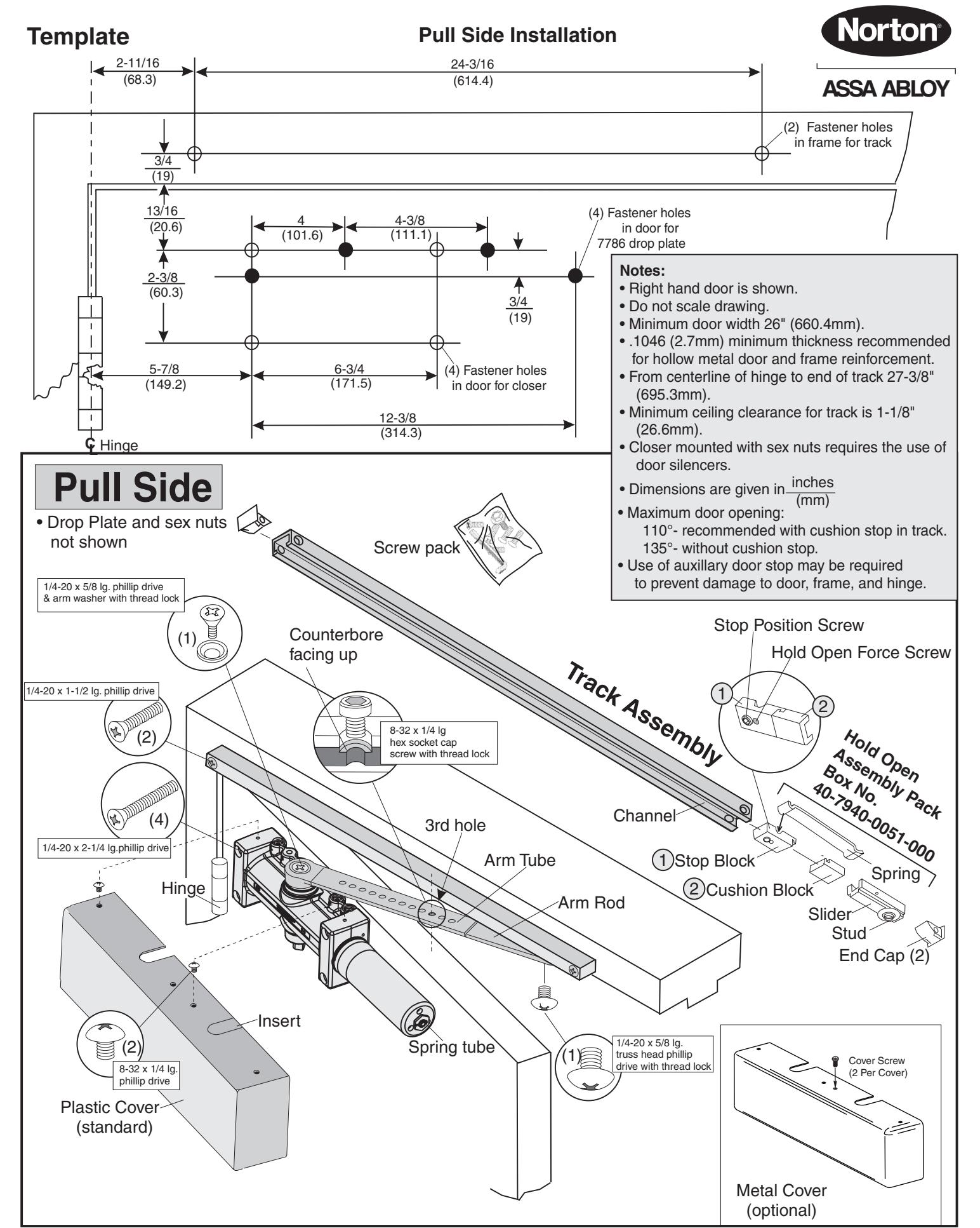
- • Use template dimensions to locate fastener holes on door and frame. See "Preparation for Fasteners" chart below.
Frame: Prepare the frame for mounting track. Drill and tap holes for 1/4-20 machine screws or #14 wood screws.
Door: Prepare the door for mounting closer. Drill and tap (4) holes for 1/4-20 machine screws, #14 wood screws, 3/8 diameter sex-nuts, or through bolts and grommet-nuts.
Note: If drop plate is used, prepare holes for 7786 drop plate instead of closer. Secure drop plate before mounting closer.
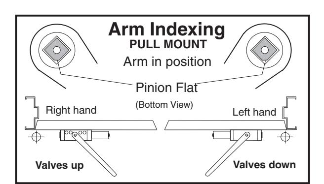
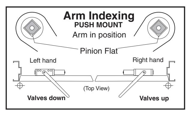
- Fasten closer to door or drop plate. Position spring tube away from hinge. See arm indexing illustrations (above right) for valve positioning (up or down). Secure mounting screws.
- Assemble Slide Arm. Insert flat arm rod into arm tube with the counterbore screw hole facing up. Align counterbore with the 3rd hole in the arm tube and secure with 8-32 x 1/4 long hex socket cap screw. See illustration on page 2 or 4.
- Install arm on closer pinion see arm indexing illustrations (above right). Position slide arm with counterbore facing up and align with pinion flat as illustrated. Install onto pinion. Secure with washer and flat head phillips drive arm screw with thread lock.
• Track Assembly
Remove slider assembly parts from box # 40-7940-0051-000 and insert into channel in the order shown. See illustration on page 2 or 4. Insert end caps into ends of track prior to installing.
| Preparation for Fasteners | ||||
|---|---|---|---|---|
| Fasteners | Door or Frame | Drill Sizes | ||
|
#14 type "A"
S.M. screw Arm: 1-1/4" (32mm) Closer: 2-3/4" (70mm) |
Wood | 7/32" (5.56mm) | ||
|
1/4" -20 machine
screw |
Metal |
drill: #7 (.201")
tap: 1/4" -20 |
||
| Sex-nuts and bolts | Hollow Metal |
9/32" (7.00mm) through
3/8" (9.50mm) door-face opposite to closer |
||
|
Aluminum or
Wood |
3/8" (9.50mm) through | |||
|
Through-bolts and
grommet-nuts (Optional) |
All |
9/32" (7.00mm) through;
3/8" (9.50mm) dia. x 3/8" (10mm) deep door face opposite to closer |
||
- • Install track to frame. Place the assembled slide track against frame with the open side down, stop and cushion blocks toward the hinge. Move the slider to the opposite end of the slide track. Secure slide track with 1/4-20 flat head phillips drive mounting screws.
- • Connect arm to track. Open door approximately 5"(127mm), rotate arm to slider and place end on stud. Push down on arm and tap gently to seat (to prevent stud from turning during assembly). Secure with 1/4-20 x 5/8" long truss (rounded) head phillips drive screw with thread lock. CAUTION: Closer arm is under spring tension and may be difficult to rotate.
- Set hold open angle for door. Open door to the angle you want the door to stop. With the door held at that location, slide stop with cushion block against slider. This may require turning the hold opening force screw (small set screw) with 1/8" hex drive to reduce tension. Tighten the stop position screw (large set screw) with 3/16" hex wrench (from screw pack) until secure. Turn the hold opening force screw until desired hold open tension is achieved, then release.
- Adjust closer (see page 5) before installing cover.
- • Install Cover. Slide insert into cover slot (see illustration). Fasten cover to closer with (2) 8-32 x 1/4" long round head phillips drive screws.
Closer Adjustments
Closing Power
7740 Models come in five different sizes (2 through 6); each power size can be increased by 50%. Adjust as required. See Figure 1.
7540 Models are fully adjustable. For proper sizing see Power Adjustment Chart. To adjust closer power, see Figure 1. Increase or decrease power as necessary.
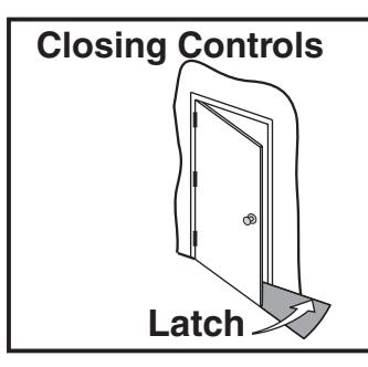
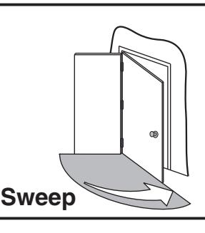
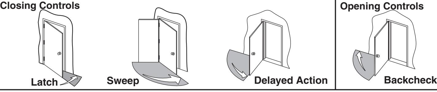
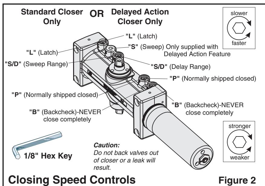
Closing Cycle (see illustrations above).
Valve "L" controls door speed in Latch Range. Valve "S" (optional) Delayed Action Closer only. Controls door speed in Sweep Range.
Valve "SD" controls door speed in Sweep Range for Standard Closer or Delay Range for Delayed Action Closer
Use 1/8" hex-key furnished and adjust all valves as shown in Figure 2.
Attention: Adjust closing speed to between 4 to 7 seconds from 90°. Use of door by handicapped, elderly or small children may require greater closing time.
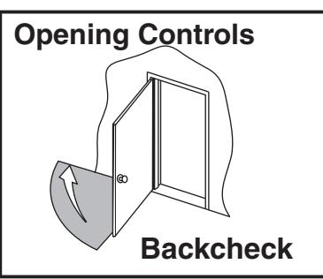
Opening Cycle (see illustration above).
Valve "B" cushions (slows) door opening in the Backcheck Range.
NOTE: Never close this valve completely or damage to closer may occur.
Valve "P" allows "backcheck" to begin later in the opening cycle when required.
| Closing Power Control | Figure 1 | ||
|---|---|---|---|
|
Install closer per instructions
with the proper pre-load applied to the arm then adjust spring power. The power adjustment will not work properly if the closer spring is not pre-loaded. To increase power, use 11/16" wrench to turn power adjustment nut clockwise. To decrease power, turn nut counter clockwise. |
"Spring Power
Adjustment Nut" + - |
||
|
DO NOT use a power drill or driver to turn
adjustment nut. This will damage closer |
|||
| Power Adjustment Chart | ||||
|---|---|---|---|---|
| Full Clockwise Turns of Closer Power Adjustment Nut | ||||
|
Door Size
Inches (mm) |
7540STH
PS7540STH |
|||
| Interior Door | Exterior Door | NOTE: Maximum of | ||
|
28-32
(0.07-0.80) |
0 | 2 |
15 turns (360°) of
Power Adjustment |
|
|
33-36
(0.85-0.90) |
2 | 5 |
Nut. Closer is
shipped set at |
|
|
37-42
(0.95-1.05) |
5 | 8 |
lowest power
setting. |
|
|
43-48
(1.10-1.20) |
8 | 11 | ||

3000 Highway 74 East • Monroe, NC 28112 Tel: (877)-974-2255 • Fax: (800)-338-0965 www.nortondoorcontrols.com
and void warranty.