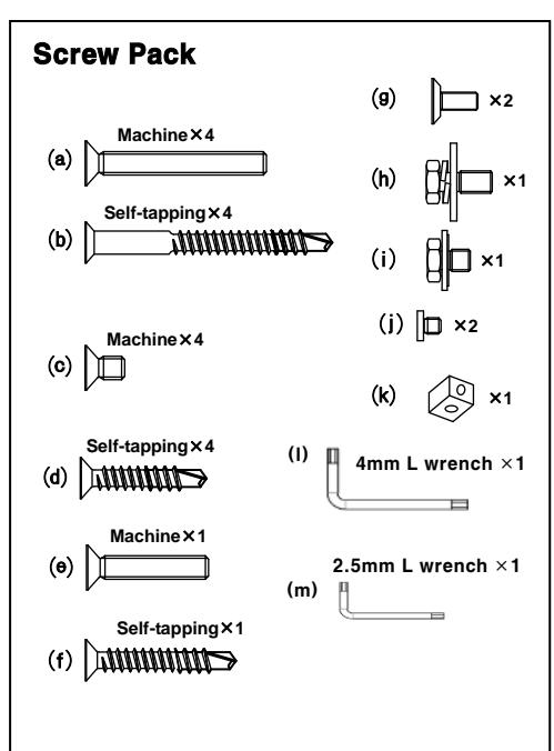
Norton 410 Series Door Closer Non-Hold Open Tri-Packed Installation Instructions
Open the original PDF document
View PDFSTANDARD MOUNT (PULL SIDE) Right Hand Door – RH
|
DOOR CLOSER
SIZE |
MAXIMUM DOOR WIDTH | FULL TURNS OF POWER | |
|---|---|---|---|
|
EXTERIOR
(SWING OUT) |
INTERIOR | ADJUSTMENT SCREW | |
| 1 | 28"(0.71m) | 32"(0.81m) | 7C.C.W |
| 2 | 32"(0.81m) | 36"(0.91m) | 4C.C.W |
| 3 | 36"(0.91m) | 42"(1.07m) | 0(PRESET) |
| 4 | 42"(1.07m) | 48"(1.22m) | 5C.C.W |
| 5 | 48"(1.22m) | 54"(1.22m) | 10C.C.W |
| 6 | 54"(1.37m) | 58"(1.47m) | 15C.C.W |
Left Hand Reverse - LHR
C.W. = CLOCKWISE C.C.W = COUNTER CLOCKWISE
PLEASE NOTE TURNS REQUIRED ARE APPROXIMATE BECAUSE OF VARIOUS DOOR CONDITIONS AND LOCATIONS. YOU MAY HAVE TO FURTHER ADJUST SPRING TENSION TO SUIT YOUR REQUIREMENTS.
IT IS IMPORTANT TO CAREFULLY FOLLOW ALL INSTALLATION AND MOUNTING INSTRUCTIONS WHEN INSTALLING ANY DOOR CLOSER.
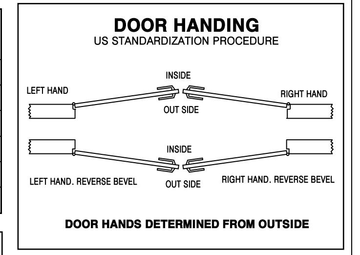
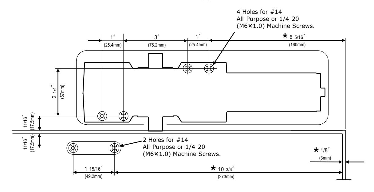
LEFT HAND DOOR shown. RIGHT HAND DOOR is opposite.
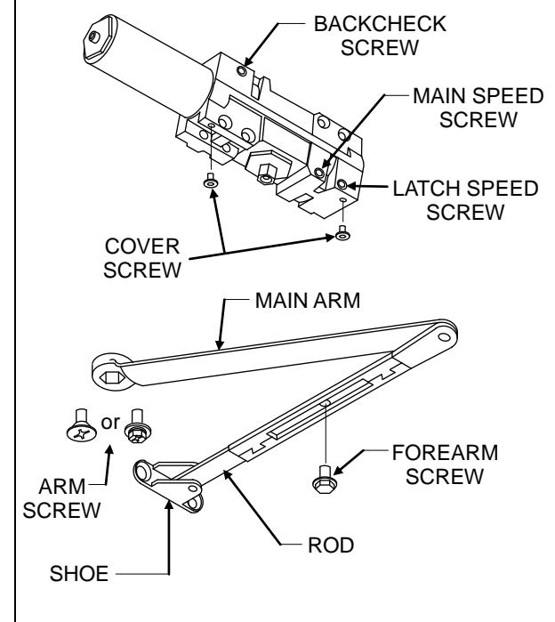
MAIN ARM
COVER
- 1. Adjust spring power to match door width as indicated by chart on page 1.
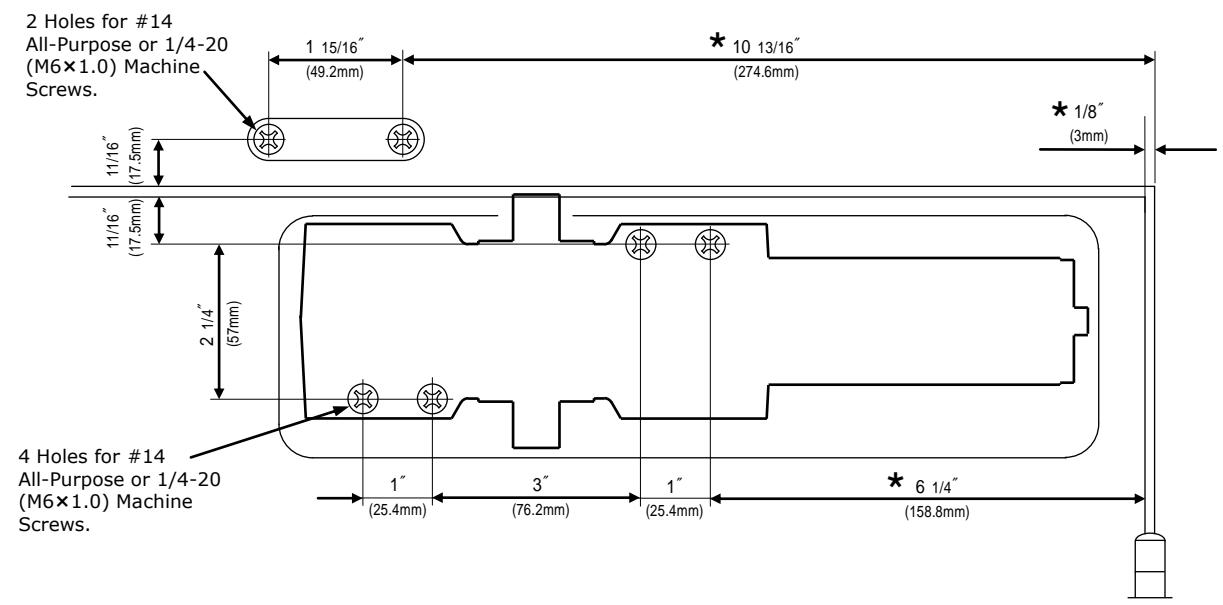
- 2. Mount closer on door as dimensions shown. Tube end toward hinge. If pivots are used, locate closer and shoe from CENTERLINE OF PIVOT.
(For offset pivots, please increase the marked dimensions by 1/8 ″ )
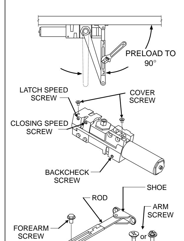
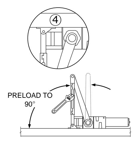
- 3. Place main arm on top of shaft, 100° to closer body, insert arm screw into top of shaft and tighten.
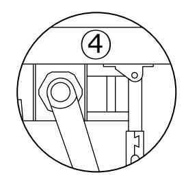
- 4. Attach shoe to frame as shown. (If more latching power is required, rotate shoe 180° from position shown in fig. 4)
- 5. Open door and insert rod in forearm.
- 6. Rotate forearm away from hinge edge of door until forearm is 90° to frame face, insert forearm, set screw and tighten.
(IF HOLD OPEN ARM IS USED, THE NUT IS ON THE TOP FOR RH DOOR AND BOTTOM FOR LH DOOR)
REGULATION:
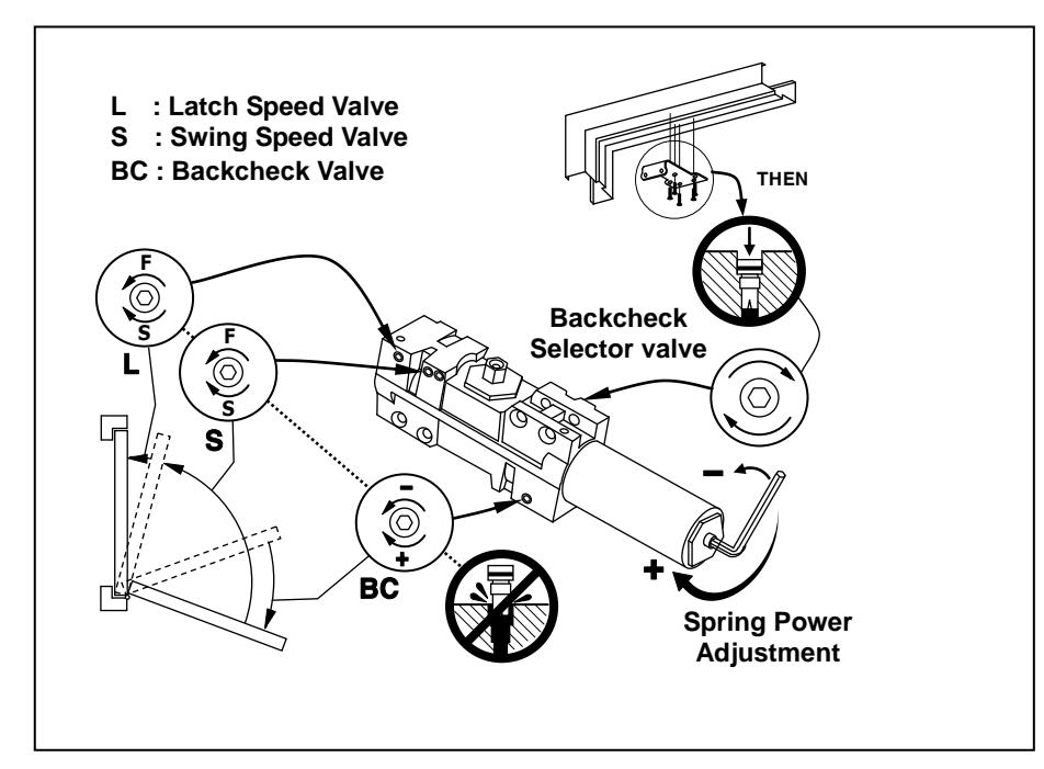
A 'Normal' closing time from 90° open position to door stop position is 4-6 secs, evenly divided between main swing speed and latch swing speed. Use socket key (furnished) to adjust speed. To slow main speed of door, turn regulating screw nearest shaft clockwise. To slow latch speed, turn regulating screw nearest latch clockwise.
BACKCHECK
To increase BACKCHECK force, turn regulating screw nearest hinge clockwise. DO NOT USE ABRUPT BACKCHECK OR EXPECT DOOR CLOSER TO ACT AS A DOOR STOP.
COVER
Place insert in proper cutout, then push cover against door. Tighten both cover screw securely.
HOLD OPEN ADJUSTMENT (when hold open arm is used)
Loose adjusting nut, open door to desired hold open position and tighten nut. Do not permit door to swing beyond hold open setting.
Page 2
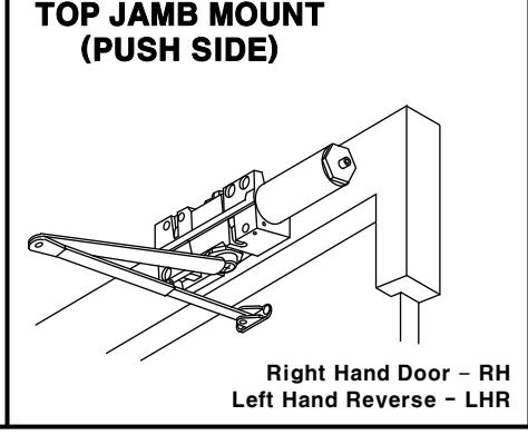
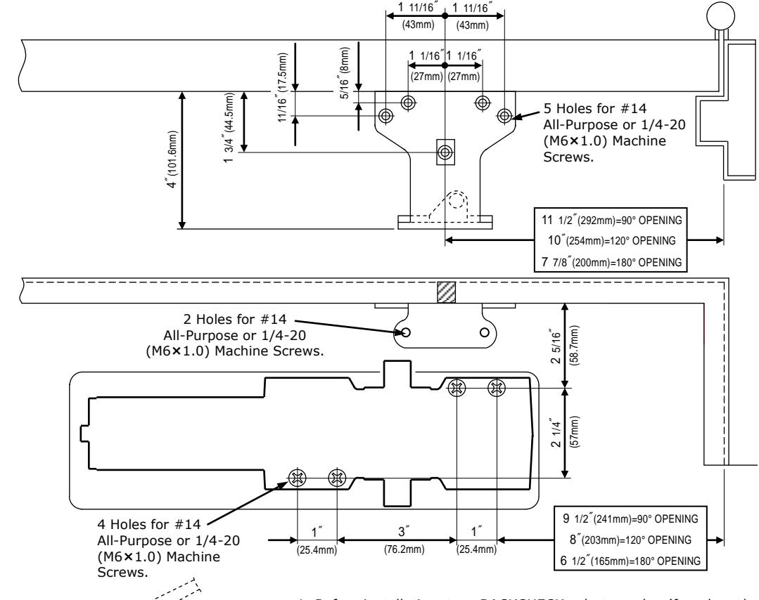
RIGHT HAND DOOR shown. LEFT HAND DOOR is opposite.
- 1. Adjust spring power to match door width as indicated by chart on page 1.
- 2. Mount closer on frame as dimensions shown. Tube end toward hinge. If pivots are used, locate closer and shoe from CENTERLINE OF PIVOT.
( For offset pivots, please increase the marked dimensions by 1/8 ″ )
- 3. Place main arm on top of shaft, 100° to closer body, insert arm screw into top of shaft and tighten.
- 4. Attach shoe to frame as shown. (If more latching power is required, rotate shoe 180° from position shown in fig. 4)
- 5. Open door and insert rod in forearm.
- 6. Rotate forearm away from hinge edge of door until forearm is 90° to frame face, insert forearm, set screw and tighten.
- (IF HOLD OPEN ARM IS USED, THE NUT IS ON THE TOP FOR RH DOOR AND BOTTOM FOR LH DOOR)
REGULATION:
A 'Normal' closing time from 90° open position to door stop position is 4-6 secs, evenly divided between main swing speed and latch swing speed. Use socket key (furnished) to adjust speed. To slow main speed of door, turn regulating screw nearest shaft clockwise. To slow latch speed, turn regulating screw nearest latch clockwise.
BACKCHECK
To increase BACKCHECK force, turn regulating screw nearest hinge clockwise. DO NOT USE ABRUPT BACKCHECK OR EXPECT DOOR CLOSER TO ACT AS A DOOR STOP.
COVER
Place insert in proper cutout, then push cover against door. Tighten both cover screw securely.
HOLD OPEN ADJUSTMENT (when hold open arm is used )
Loose adjusting nut, open door to desired hold open position and tighten nut.
30°
BACKCHECK SCREW
or
ARM SCREW
BACKCHECK SELECTOR SCREW
FOREARM SCREW
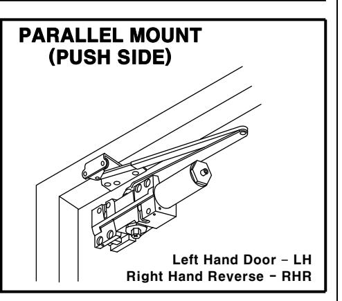
RIGHT HAND DOOR shown. LEFT HAND DOOR is opposite.
- 1. Before installation, turn BACKCHECK selector valve (found on the opposite side of closer from backcheck screw side) ALL THE WAY IN CLOCKWISE.
- 2. Adjust spring power to match door width as indicated by chart on page 1.
- 3. Mount closer on door at dimensions shown with tube end toward latch edge of door. If pivots are used, locate closer and parallel bracket from CENTERLINE OF PIVOT.
- 4. Place open end wrench on bottom shaft and turn toward hinge jamb about 30°. and then place main arm on top shaft, insert arm screw into top of shaft and tighten.
- 5. Attach parallel bracket on frame at dimensions shown.
- 6. Attach rod and shoe to parallel bracket as shown.
- 7. Insert rod in forearm, and rotate main arm parallel to door. Then insert forearm set screw and tighten.
(IF HOLD OPEN ARM IS USED, THE NUT IS ON THE TOP FOR RH DOOR AND BOTTOM FOR LH DOOR)
REGULATION:
A 'Normal' closing time from 90° open position to door stop position is 4-6 secs, evenly divided between main swing speed and latch swing speed. Use socket key (furnished) to adjust speed. To slow main speed of door, turn regulating screw nearest shaft clockwise. To slow latch speed, turn regulating screw nearest hinge clockwise.
BACKCHECK
To increase BACKCHECK force, turn regulating screw nearest latch clockwise. DO NOT USE ABRUPT BACKCHECK OR EXPECT DOOR CLOSER TO ACT AS A DOOR STOP.
COVER
Place insert in proper cutout, then push cover against door. Tighten both cover screw securely.
HOLD OPEN ADJUSTMENT (when hold open arm is used)
Loose adjusting nut, open door to desired hold open position and tighten nut. Do not permit door to swing beyond hold open setting.

MAIN SPEED SCREW
PARALLEL BRACKET
SPACER BLOCK
LATCH SPEED SCREW