Norton 210 Series Door Closer Non-Hold Open or Hold Open Heavy-Duty Arm Installation Instructions
Open the original PDF document
View PDFINSTALLATION INSTRUCTIONS
Power sizes 1 thru 6
- Heavy-Duty Non-Hold Open Parallel Arm w/Removable Stop
- Heavy-Duty Hold Open Parallel Arm w/ Thumbturn and Removable Stop
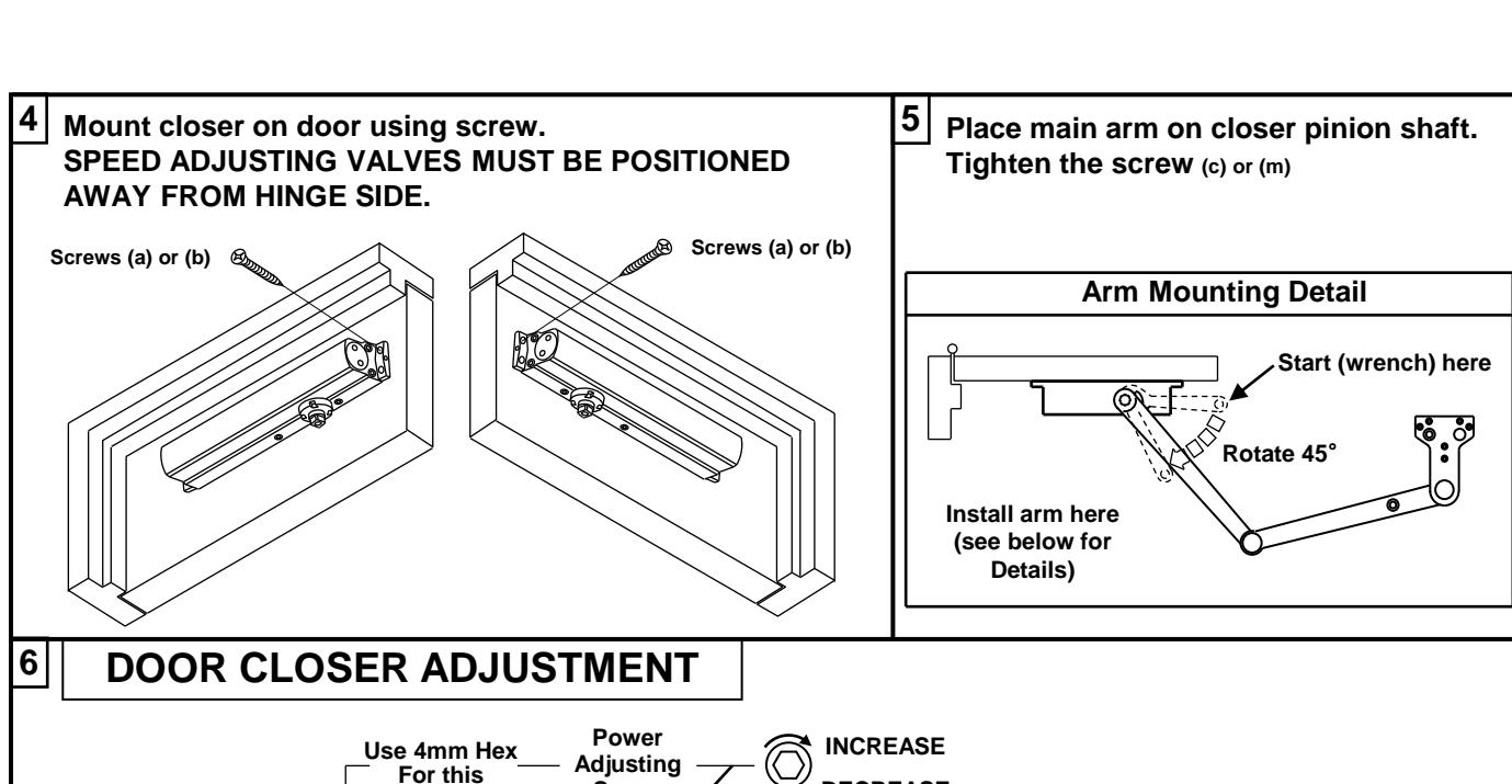
Using the measurements from diagram, mark screw hole center locations. Mark four (4) holes on door to mount door closer and five (5) holes on frame to mount parallel bracket. Drill 7/32" or drill #7 and tap for 1/4-20.
| Metal | Wood |
|---|---|
| #7 | |
| 1/4-20 | 3/16 " |
Incorrect installation or adjustment could cause damage or injury. Read and follow instructions carefully.
| OPENING | DIMENSION A |
|---|---|
| 85°~ 90° | 3 (76) |
| 90°~ 95° | 2-13/32 (61) |
| 95°~ 100° | 1-13/16 (46) |
| 100°~ 105° | 1-1/4 (31) |
| 105°~ 110° | 5/8 (16) |
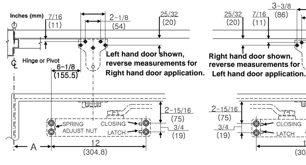
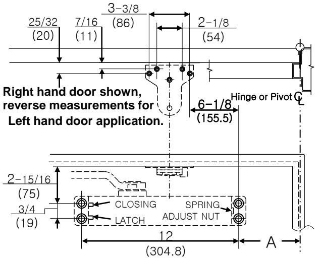
BRACKET ADJUSTMENT
All brackets are shipped assembled for left hand door. The following adjustments must be made before installing bracket to top frame.
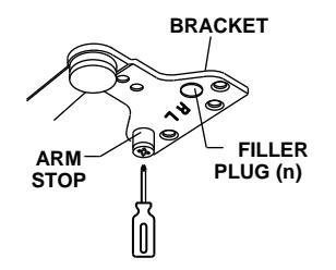
FOR LEFT HAND DOOR:
Using the phillips screwdriver, turn the REMOVABLE ARM STOP clockwise to seat as tightly as possible. Push filler plug in firmly.
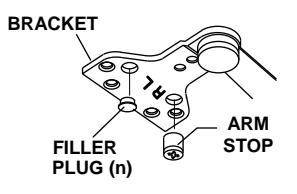
FOR RIGHT HAND DOOR: Remove filler plug from bracket. Using the phillips screwdriver turn the REMOVABLE ARM STOP counter-clockwise to remove it. Insert REMOVABLE ARM STOP into hole mark "R" and using the phillips screwdriver, turn clockwise to seat as tightly as possible. Push filler plug into the other hole firmly.
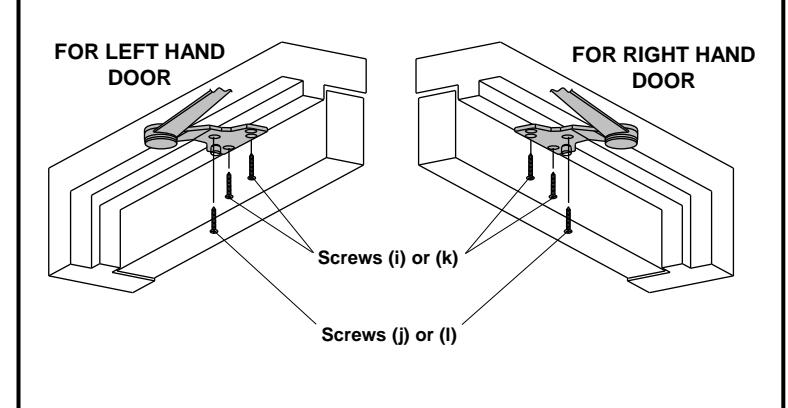
3 Installing bracket to top frame.
(45~65 Kg)
143~187 LBS
4 + 3 48 " (1.22m) 42 "(1.07m) (65~85 Kg) 187~264 LBS (85~120 Kg) 5 + 8 54 " (1.37m) 48 "(1.22m) 264~330 LBS 6 ± 11 58 " (1.47m) 54 "(1.37m) (120~150 Kg)
SLOWER FASTER CLOSING CYCLE
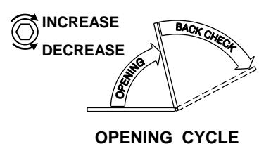
CAUTION!! Do not turn speed adjusting valve more than two(2) full turns counter-clockwise. Do not back valves out of closer or a leak will result.
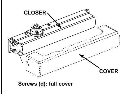
7 Install full cover, using small screws.
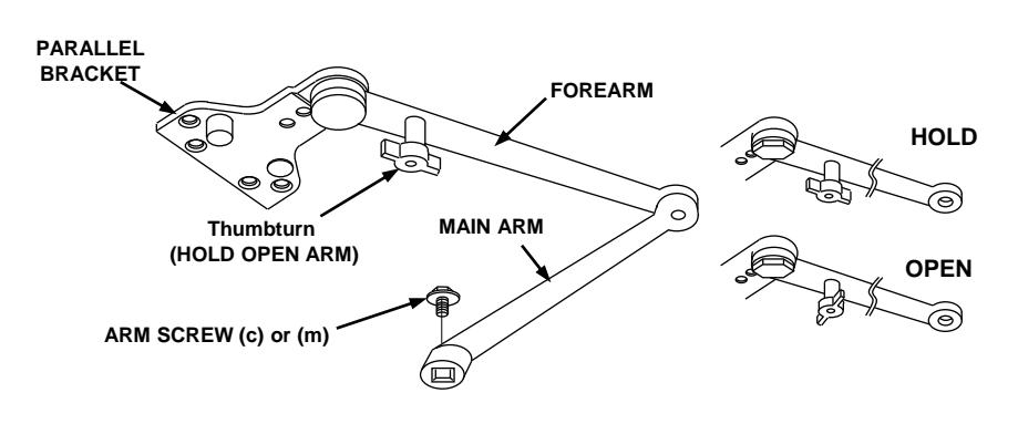
HOW TO ENGAGE THUMBTURN
Turn one guarter turn to engage or disengage.