Norton 210 Series Door Closer Non-Hold Open Tri-Packed Installation Instructions
Open the original PDF document
View PDFNon Hold Open Door Closer
AN INCORRECTLY INSTALLED OR IMPROPERLY ADJUSTED DOOR CLOSER CAN CAUSE PROPERTY DAMAGE OR PERSONAL INJURY. THESE INSTALLATION INSTRUCTIONS SHOULD BE FOLLOWED TO AVOID THE POSSIBILITY OF MISAPPLICATION OR MISADJUSTMENT.
Installation Instructions
Power size 1 thru 6
Unit Adjustment
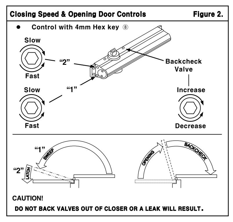
Control Valve Adjustments
(see Figure 2)
Closing Speed Controls (Figure 2)
- Valve "1" Controls Sweep Range
- Valve "2" Controls Latch Range
Opening Cycle
"Backcheck" valve controls the strength of cushioning in Backcheck Range. NEVER close this valve completelyit is not to provide a positive stop. (see Figure 2)
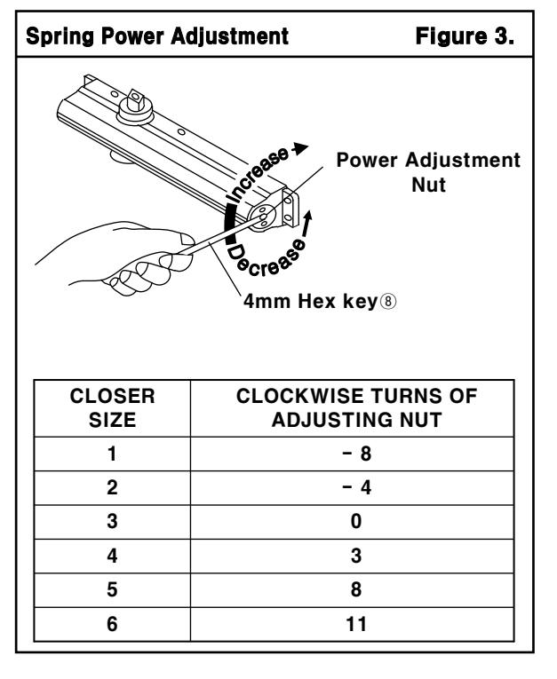
Closing Power Adjustment
Using "Power Adjustment Chart" from page 3,4 or 5, Select the correct number of turns for power adjustment nut that corresponds with the installation. With 4mm Hex key, rotate adjustment nut full 360°(clockwise) to desired setting. After closer has been installed and proper adjustments made to the sweep and latch, it may be necessary to readjust spring power for good closing action.
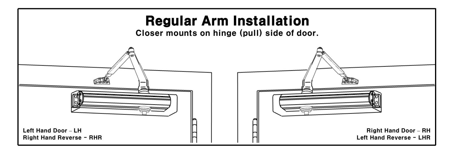
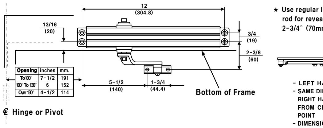
Regular Arm
Installation Instructions
Template
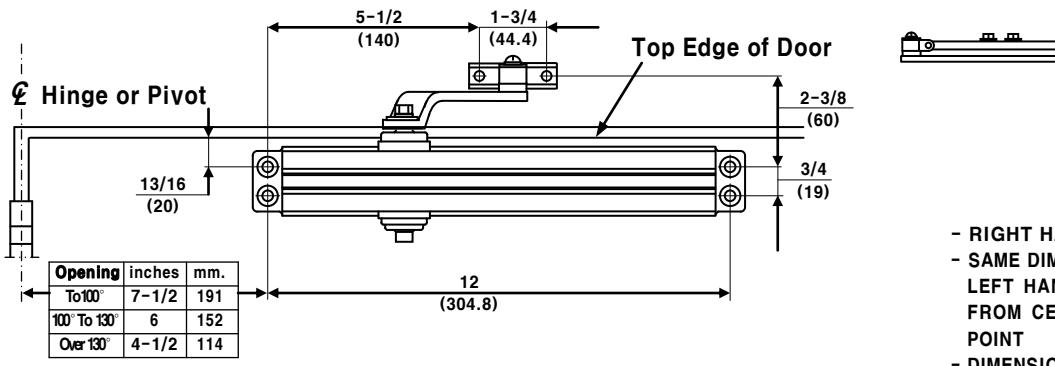
- RIGHT HAND DOOR SHOWN
- SAME DIMENSIONS APPLY FOR LEFT HAND DOOR MEASURED FROM CENTERLINE OF PIVOT POINT
- DIMENSIONS ARE IN INCHES (mm.)
PLEASE NOTE
- This drawing is not to scale.
- Therefore, do not use it as your template to locate the hole positions while you fabricate your door and frame for the installation of this product.
INSTALLATION INSTRUCTIONS
- Select angle of opening and use dimensions shown to locate 4 HOLES ON DOOR for closer body and 2 HOLES ON FRAME face for arm shoe.
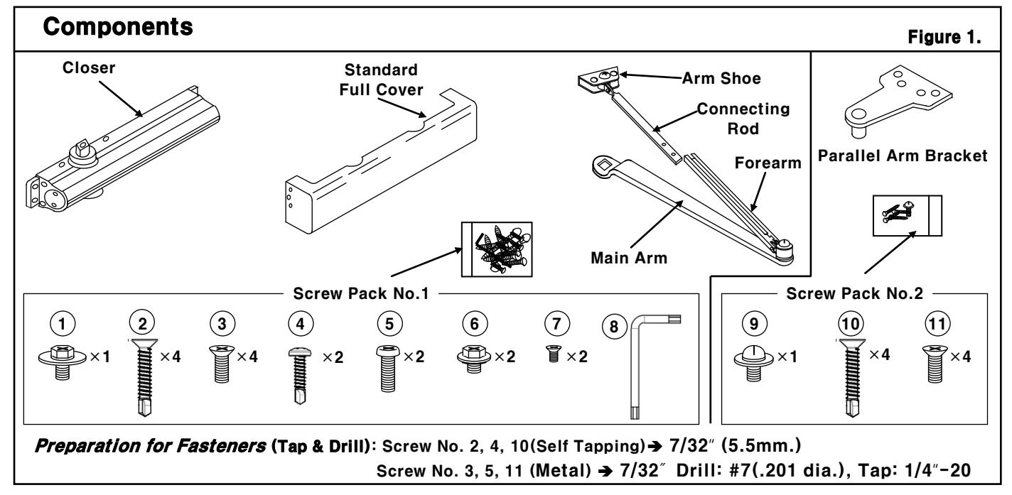
- Prepare door and frame for fasteners. See "Preparation for Fasteners", page 1-figure 1.
- Mount closer body on door with screws ②or③, page 1-figure 1.
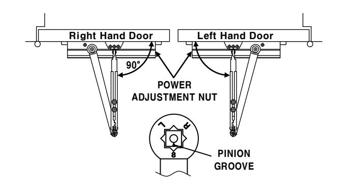
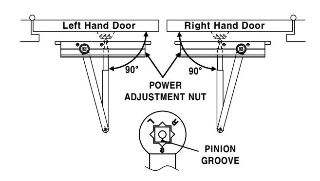
Be sure that power adjustment nut is away from hinge.
- Place main arm on closer pinion shaft with screw ① page 1-figure 1. Indexing main arm mark "S" with pinion groove as shown at right.
- Fix arm shoe to frame with screws ④or⑤, page 1-figure 1.
- Insert connecting rod into forearm.
- Pull main arm toward opposite side of hinge so that connecting rod will be perpendicular to door. Fix connecting rod on forearm using screws (6), page 1-figure 1.
- Set closing power for door size using Chart, page 1-figure 3.
- Adjust closer and install cover (use screws ①, page 1- figure 1.)
- See page 1- figure 2 for closer adjustment.
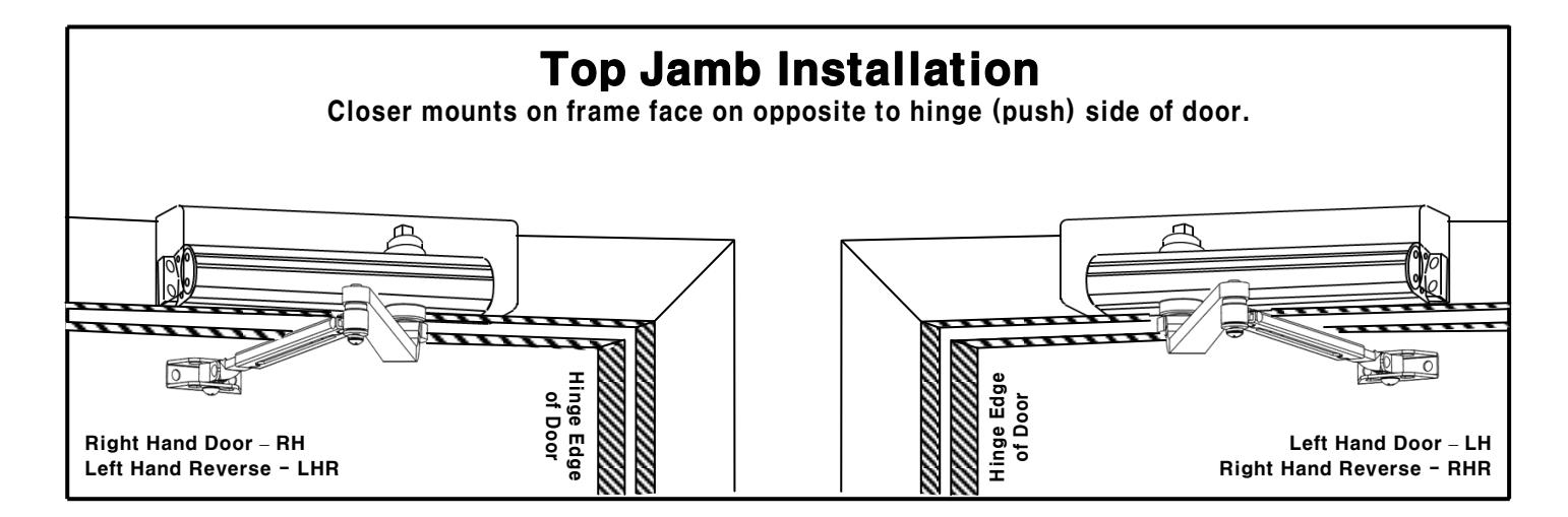
Top Jamb
Installation Instructions
Template
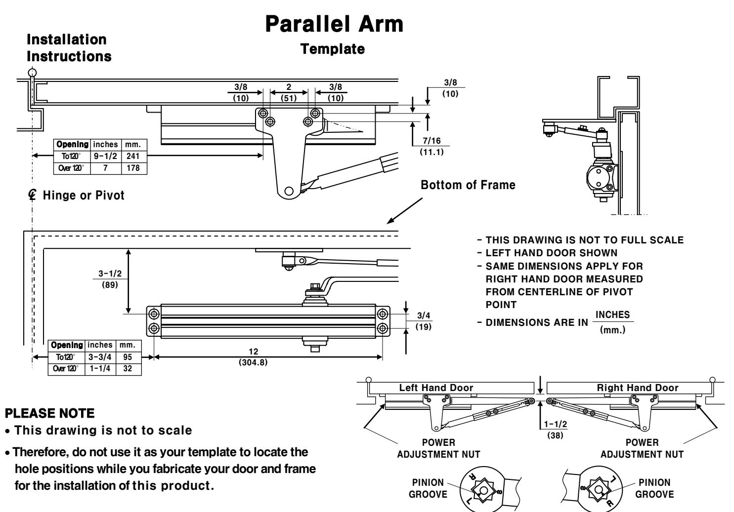
* Use regular length rod for reveals to 2-3/4" (70mm.)
- LEFT HAND DOOR SHOWN
- SAME DIMENSIONS APPLY FOR RIGHT HAND DOOR MEASURED FROM CENTERLINE OF PIVOT POINT
- DIMENSIONS ARE IN INCHES (mm.)
PLEASE NOTE
- This drawing is not to scale
- Therefore, do not use it as your template to locate the hole positions while you fabricate your door and frame for the installation of this product.
INSTALLATION INSTRUCTIONS
- Select angle of opening and use dimensions shown to locate 4 HOLES ON FRAME for closer body and 2 HOLES ON DOOR face for arm shoe.
- Prepare door and frame for fasteners. See "Preparation for Fasteners", page 1-figure 1.
- Mount closer body on frame with screws ②or③, page 1- figure 1.
Be sure that power adjustment nut is away from hinge.
- Place main arm on closer pinion shaft with screw ① page 1-figure 1. Indexing main arm mark "S" with pinion groove as shown at right.
- Fix arm shoe to door with screws @or5, page 1-figure 1.
- Insert connecting rod into forearm.
- Pull main arm toward opposite side of hinge so that connecting rod will be perpendicular to door. Fix connecting rod on forearm using screws (6), page 1-figure 1.
- Set closing powers for door size using Chart, see page 1 -figure 3.
- Adjust closer and install cover (use screws ①, page 1- figure 1.)
- See page 1-figure 2 for closer adjustment.
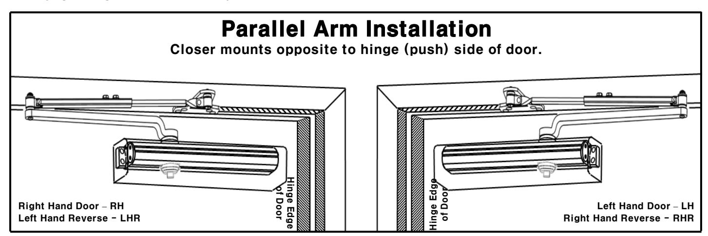
INSTALLATION INSTRUCTIONS
- Select angle of opening and use dimensions shown to locate 4 HOLES ON DOOR for closer body and 4 HOLES ON FRAME face for parallel arm bracket.
- Prepare door and frame for fasteners. See "Preparation for Fasteners", page 1-figure 1.
- Mount closer body on door with screws 2 or 3, page 1-figure 1. Be sure that power adjustment nut is toward hinge.
- Place main arm on closer pinion shaft with screw ① page 1-figure 3. Index main arm (mark "L" or "R") with pinion groove as shown at right.
- Fix parallel arm bracket to frame with screws @orff, page 1-figure 1.
- Disconnect arm shoe from connecting rod by removing screw. Remove arm shoe from connecting rod and discard. Assemble parallel arm bracket to connecting rod with screw (9), page 1-figure 1.
- Insert connecting rod into forearm.
- With door closed, adjust length of forearm and connecting rod so that the tip of the main arm is 1-1/2" (38mm.) from parallel with door. Secure with screws ®, page 1.
- Set closing powers for door size using Chart, page 1-figure 3.
- Adjust closer and install cover (use screws ①, page 1-figure 1.)
- See page 1-figure 2 for closer adjustment.