Norton 1700 Series Door Closer Hold Open Installation Instructions
Open the original PDF document
View PDFInstallation Instructions

An incorrectly installed or improperly adjusted door closer can cause property damage or personal injury. These instructions should be followed to avoid the possibility of misapplication or misadjustment.
Hold Open Door Closers 1700H
/ WARNING
This product can expose you to lead which is known to the state of California to cause cancer and birth defects or other reproductive harm. For more information go
Installation Instructions
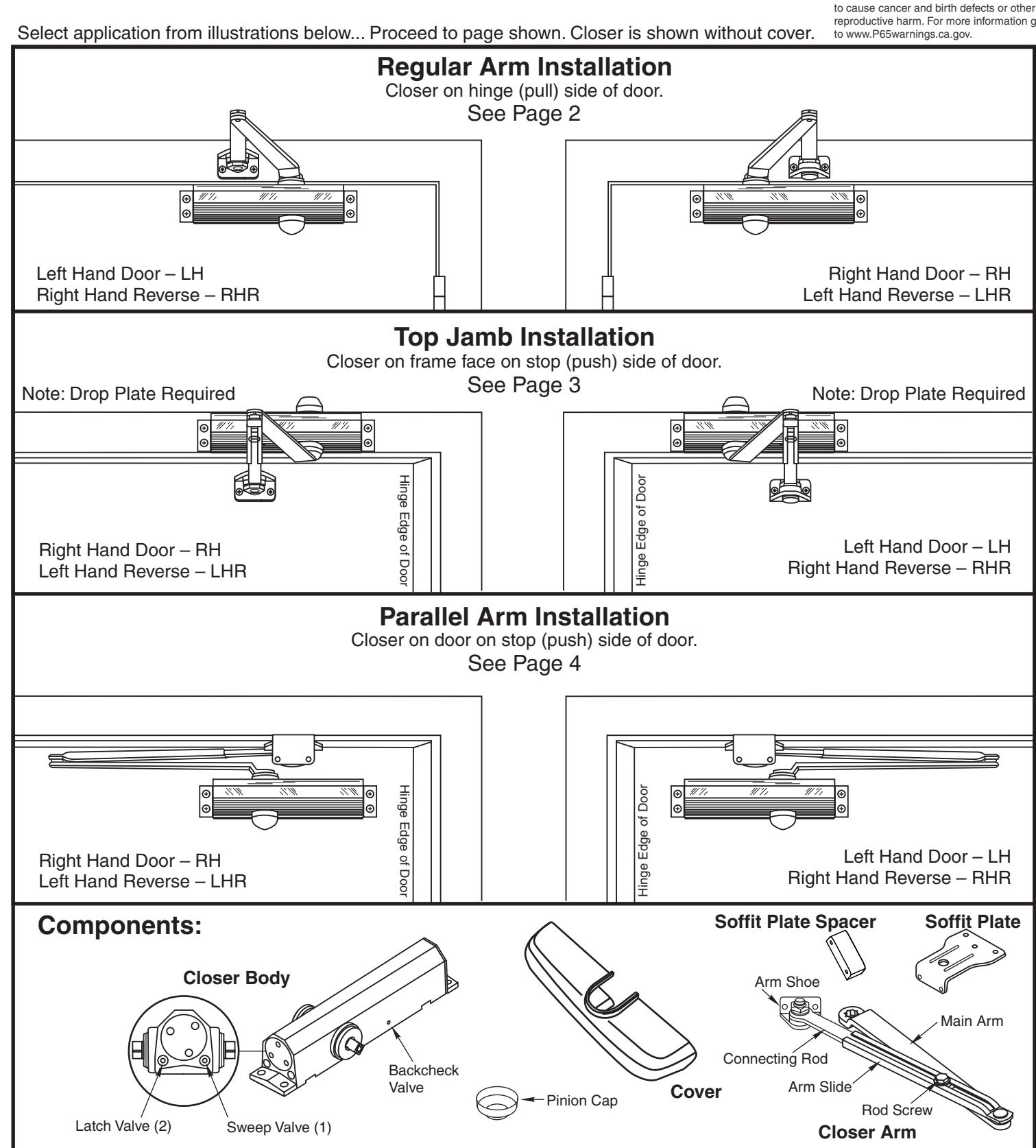
Regular Arm Mount
Norton
(By Others)
-
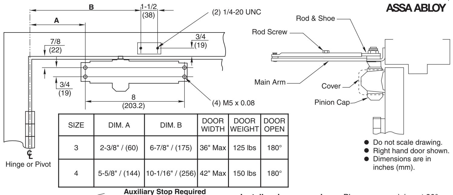
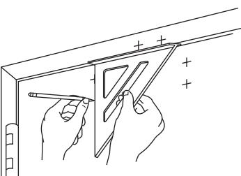
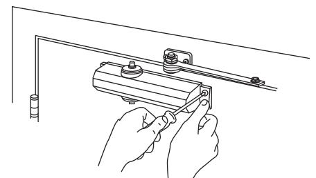
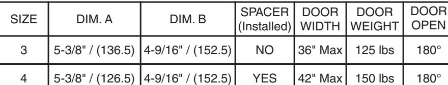
Select size mounting. Use template to locate holes on door and frame:
- 4 on door for closer. 2 on frame face for arm shoe.
- Prepare for fasteners. See Chart on Page 2.
- · Remove rod and shoe from arm assembly.
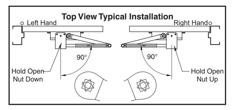
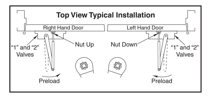
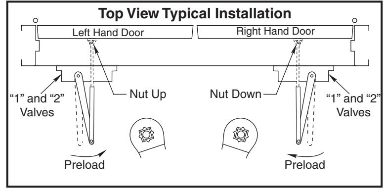
- Mount rod and shoe to frame. Nut Up for Right Hand door Nut Down for Left Hand door
- Mount closer to door. Place end with two regulating valves toward hinge edge of door.
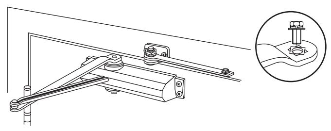
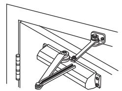
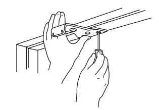
Install main arm on closer. Place arm on pinion at 90° angle (perpendicular) to frame, see "Typical Installation" chart below. Fasten with arm screw.
- Open door slightly. Align and insert adjusting rod into adjusting tube. Close door. Adjust forearm at 90° angle (perpendicular) to door. Tighten rod screw.
- Adjust closer. See Page 3 ... Then install pinion cap or cover.
| Fasteners Chart | |||
|---|---|---|---|
| ≥ | Fasteners | Door or Frame | Drill-Sizes |
| Closer Body | 5.5mm Dia. type "A" sheet metal screw | Wood | 3/32" (2.5 mm.) |
| M5 X 0.8 FHMS | Metal |
Drill: #19 (4.2mm dia.)
Tap: M5 X 0.8 |
|
| Soffit Plate & Arm | Fasteners | Door or Frame | Drill-Sizes |
|
#14 type "A" sheet
metal screw |
Wood | 7/32" (5.56 mm.) | |
| 1/4" - 20 machine screw | Metal |
Drill: #7 (0.201" dia.) Or 5.10mm
tap: 1/4" - 20 |
|
Installation Instructions
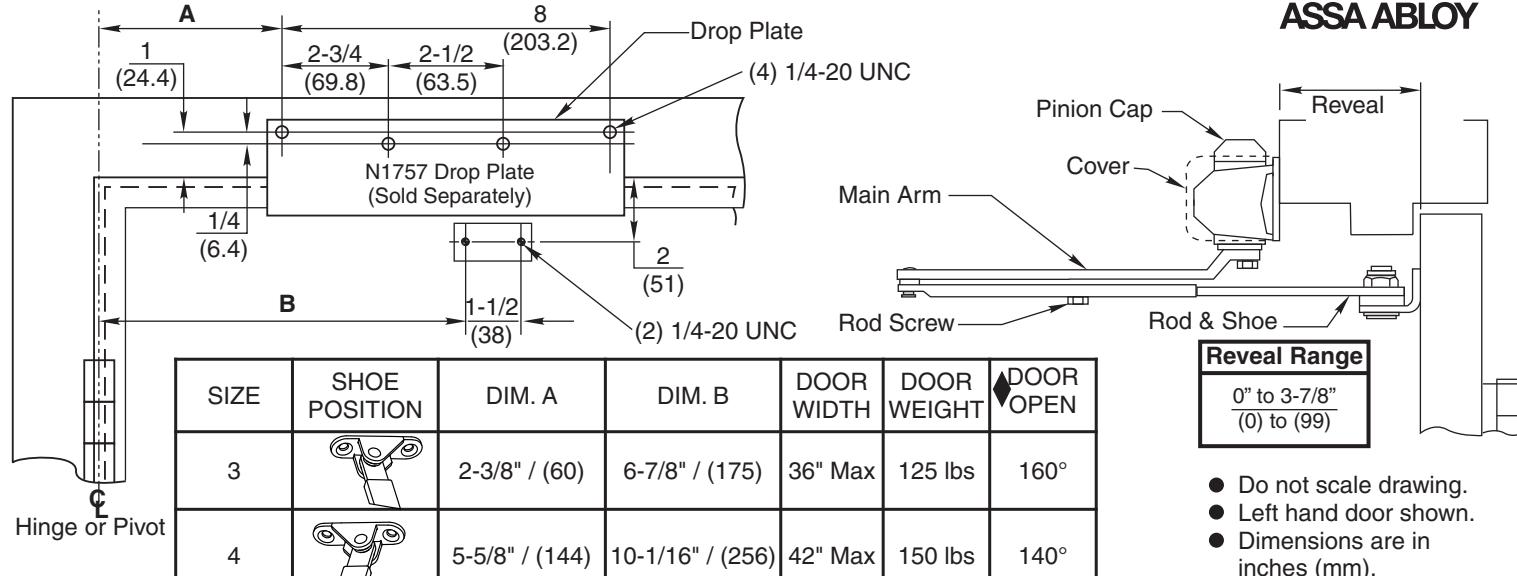
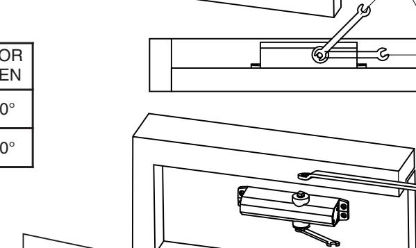
Top Jamb Mount 1700H

Max. Door Open:
Size 3: 160° max. open at 3" to 3-7/8" reveals.
Size 3: 180° max. open at 0" to 3" reveals.
Size 4: 140° max. open 0" to 3-7/8" reveals.
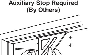
Auxiliary Stop Required (By Others)
- Select size mounting. Use template to locate holes on door and frame:
- 4 on frame face for closer, 2 on door for arm shoe.
- Prepare for fasteners. See Chart on Page 2.
- Remove rod and shoe from arm assembly.
- Mount rod and shoe to door. Nut Down for Right Hand door. Nut Up for Left Hand door.
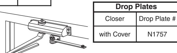
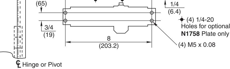
- Fasten No. N1757 drop plate to frame face.
- Mount closer to drop plate using (4) M5 x 0.08 screws provided. Place end with two regulating valves toward hinge edge of door.
- Install main arm on closer. Place arm on pinion at 90° angle (perpendicular) to frame, see "Typical Installation" chart below. Fasten with arm screw.
- Reassemble arm. Adjust forearm at 90° angle (perpendicular) to door. Tighten rod screw.
- Adjust closer. See below for Hold Open, Closing Speed and Backcheck.
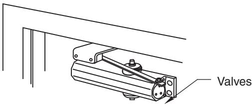
Valve Adjustments
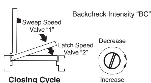
Closing Speeds "1" and "2"
- Closing speed controlled by valve marked "1" (sweep range) and by valve marked "2" (latch range).
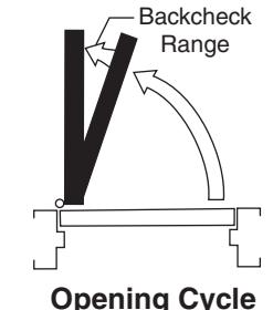
- Backcheck Model Closers only suffix "BC". Backcheck controlled by valve "BC". Never close "BC" valve completely.
- Hold Open Adjustment. Open door to angle of hold open desired. Tighten hold open adjustment nut with a 13/16" wrench or socket.
Instructions
A
B
2-9/16
1 (25.4)
2-3/4 (69.8)
2 (50.8)
Parallel Arm Mount Installation 1700H
(3) 1/4-20 UNC
1/2 (50.8)
1-1/4 (32)
3/8 (9.5)


- ! Remove rod and shoe from arm assembly.
- ! Fasten rod and shoe to soffit plate.
- ! Nut Up for Right Hand door.
- ! Nut Down for Left Hand door.
! Mount closer or drop plate and closer to door. Place end with two regulating valves toward lock edge of door.

- Left hand door shown.
- Dimensions are in
inches (mm).
! Preload Closer. Place wrench on bottom pinion and rotate wrench 45° away from door face.
2-1/2 (63.5)
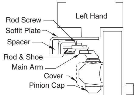

- 4 on door for closer (or drop plate).
- 3 on frame for soffit plate.
- · Prepare for fasteners. See Chart on Page 2.
· Mount soffit plate to frame.
Adjust closer. See Closer Adjustment (Pages 2 & 3). Reassemble arm. Adjust forearm length to set arm elbow from door as shown below. Tighten rod screw.