Norton 1680 & 1681 Series Sized Closers Narrow Profile Non-Hold Open Installation Instructions
Open the original PDF document
View PDF

ASSA ABLOY
Installation Instructions
An incorrectly installed or improperly adjusted door closer can cause property damage or personal injury. These instructions should be followed to avoid the possibility of misapplication or misadjustment.
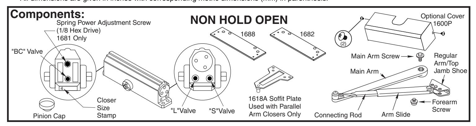
Narrow Profile Series 1680 Series Sized Closers 1681 Series Multi-Sized Closers Non Hold Open Models
Sized (Sizes 3 & 4)
1683BC 1684BC
Multi-Sized (Sizes 1 thru 6) 1681
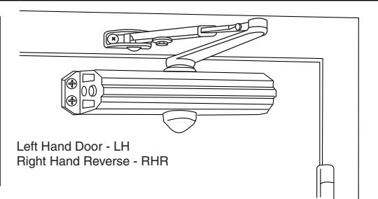
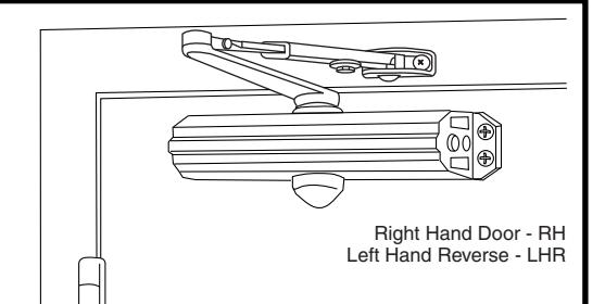
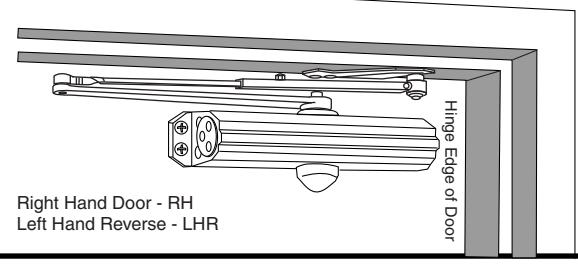
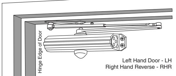
Regular Arm Installation
Closer on door on hinge (pull) side of door
See Page 2
Top Jamb Installation
Closer on frame on opposite to hinge (push) side of door
See Page 3
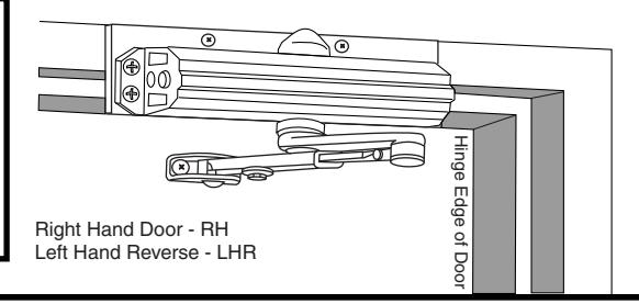
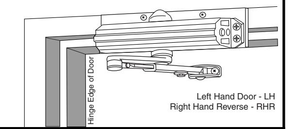
Parallel Arm Installation
Closer on door on opposite to hinge (push) side of door
See Page 4
NOTE: For special applications a separate door and frame preparation template is packed with these instructions Use this instruction sheet for installation sequence and closer adjustments only
- It is recommended that the door on which the door closer will be installed be hung on ball bearing hinges. Door must swing freely
- A separate door stop, supplied by others, is recommended to prevent damage to the door closer, closer arm, or to the door, frame or adiacent walls.
- Door and Frame must be properly reinforced, or use of special fasteners employed, to prevent the mounting screws from pulling out.
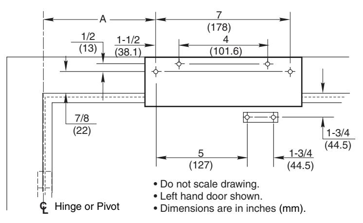
- All dimensions are given in inches with corresponding metric dimensions (mm) in parenthesis.
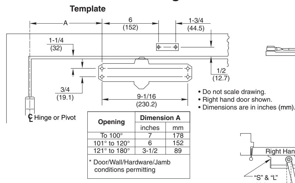
Regular Arm Installation
(12.7)
Installation Sequence
- Select door opening angle using template above. Mark 4 holes on door for closer and 2 holes on frame for arm shoe.
- Prepare door and frame for fasteners See "Preparation for Fasteners" below.
- 1681 Models Only. Set approximate closing power using "Power Adjustment Chart" below right. Closer power is set at mid range from factory.
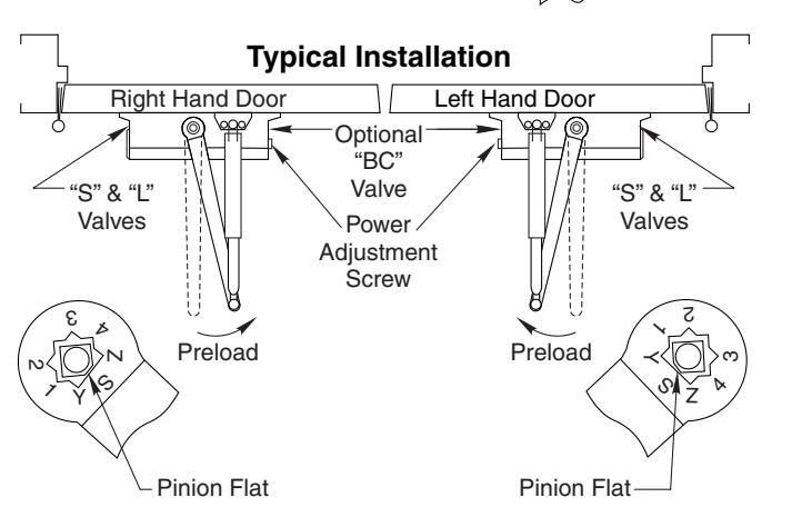
- . Install closer with "S" and "L" adjustment valves toward hinge edge of door. If using optional cover see "Cover" instructions.
- Mount arm shoe to frame face.
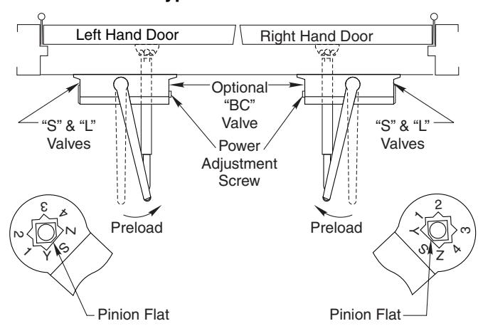
- · Install main arm onto closer pinion shaft, indexing main arm mark "S" with pinion flat as shown at right. Fasten with arm screw.
| Preparation for Fasteners | |||||||
|---|---|---|---|---|---|---|---|
| Fasteners Door or Frame Drill-Sizes | |||||||
| Standard | Self-Drilling Screw |
Aluminum
or Metal |
No drill required | ||||
| Wood |
3/16" (4.30 mm)
Pilot hole required |
||||||
| 1/4" - 20 machine screw | Metal |
Drill: #7 (0.201" dia.)
Tap: 1/4" - 20 |
|||||
| Optional | Sleeve nuts and bolts |
Hollow
Metal |
9/32" (7 mm) through;
3/8" (9.5 mm) door face opposite to closer |
||||
| Aluminum or Wood | 3/8" (9.5 mm) through | ||||||
| Through-bolts and grommet-nuts | All |
9/32" (7 mm);
3/8" (9.5 mm) dia. x 3/8" (9.5 mm) deep on door opposite to closer |
|||||
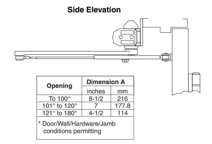
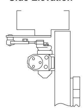
Side Elevation
- •Open door to allow connecting rod to be inserted into arm slide. Insert rod and close door. Preload main arm by rotating away from hinge until forearm is perpendicular (at 90° angle) to door. Secure with forearm screw.
- •Screw pinion cap onto pinion shaft by hand or with a Phillips screw driver -DO NOT OVERTIGHTEN. Skip this step if optional cover is used.
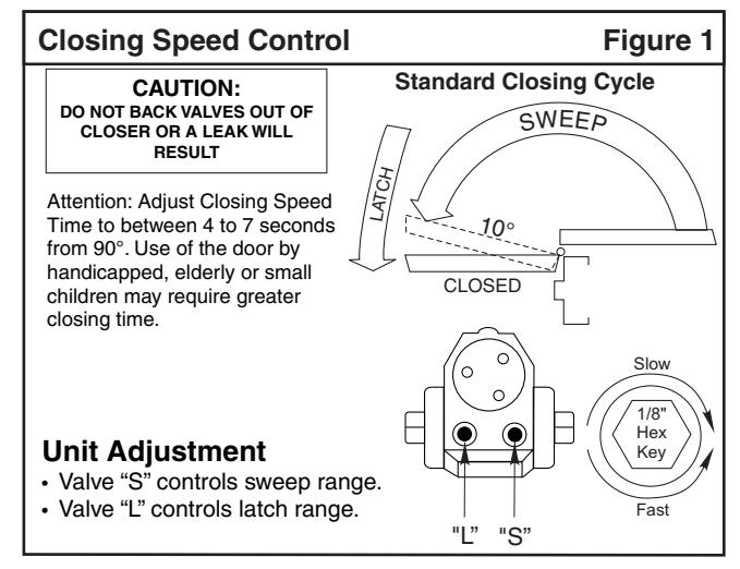
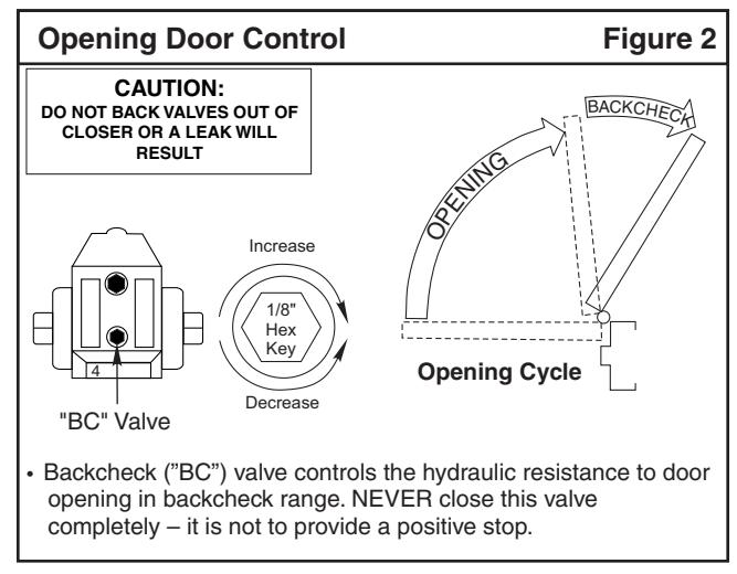
- · Adjust closer.
Door Closer Adjustment
| Adjustment Chart | Number of Turns Required | |||||||
|---|---|---|---|---|---|---|---|---|
| Π| TYPE | * | MAXIMUM DOOR SIZE | |||||
| DOOR |
OF
INST. |
34"
(0.85M) |
36"
(0.90M) |
40"
(1.00M) |
44"
(1.10M) |
48"
(1.20M) |
||
|
1681
EXTERIOR INTERIOR |
RIOR |
Regular Arm
Top Jamb |
FULL 360° TURNS OF
3/16 POWER ADJUSTMENT WRENCH |
2 | 4 | 6 | 10 | 12 |
| INTE | Parallel Arm | 3 | 5 | 8 | 11 | 14 | ||
| RIOR |
Regular Arm
Top Jamb |
3 | 5 | 8 | 11 | 14 | ||
| ЕХТЕ | Parallel Arm | 5 | 8 | 11 | 16 | 19 | ||
| *30 FULL (360°) TURNS MAXIMUM AVAILABLE | ||||||||
| = 8 Turns As Shipped | ||||||||
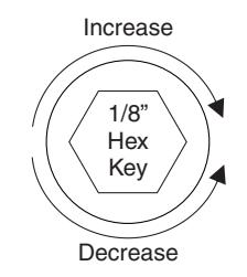
Increase
Decrease
ASSA ABLOY, the global leader in door opening solutions
Top Jamb Installation Using 1687 Dropplate
Norto

Installation Sequence
- Select door opening angle using template above. Mark 4 holes on frame face for Drop Plate and 2 holes on door for arm shoe.
- Prepare door and frame for fasteners. See "Preparation for Fasteners" at bottom of Page 2.
- 1681 Models Only. Set approximate closing power using "Power Adjustment Chart" at bottom of Page 2.
- •Mount Drop Plate to frame.
- Install closer to Drop Plate with "S" and "L" adjustment valves toward hinge edge of door. If optional cover is used see "Cover" instructions
- Mount arm shoe to door.
- Install main arm onto closer pinion shaft, indexing main arm mark "S" with pinion flat as shown at right. Fasten with arm screw.
- Open door to allow connecting rod to be inserted into arm slide. Insert rod and close door. Preload main arm by rotating away from hinge until forearm is perpendicular (at 90° angle) to door. Secure with forearm screw.
ASSA ABLOY
Typical Installation
- Screw pinion cap onto pinion shaft by hand or with a Phillips screw driver -DO NOT OVER TIGHTEN. Skip this step if optional cover is used.
- Adjust closer.
Door Closer Adjustment (Continued)
"DA" suffix (Delayed Action) is an optional feature.
A separate instruction will be packed with these instructions showing valve locations and adjustment procedures.
Parallel Arm Installation
Template
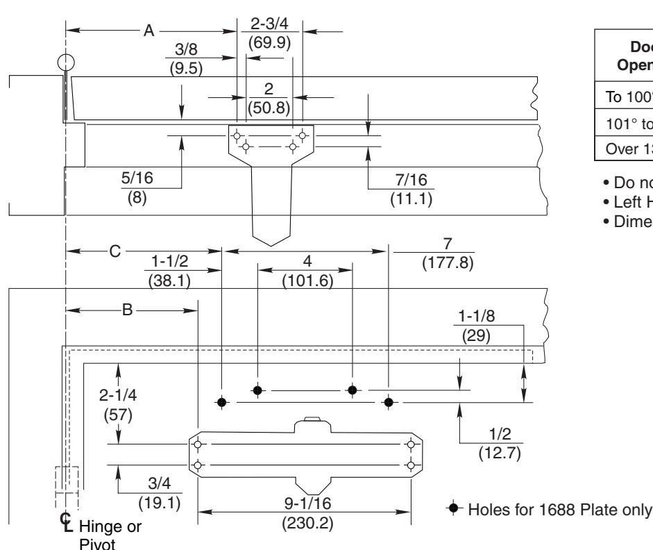
| Door | Dimension A | Dimension B | Dimension C | |||
|---|---|---|---|---|---|---|
| Opening | Inches | mm | Inches | mm | Inches | mm |
| To 100° | 9-1/4 | 235 | 7-5/8 | 194 | 8-5/8 | 219 |
| 101° to 130° | 7-3/4 | 197 | 6-1/8 | 156 | 7-1/8 | 181 |
| Over 131° | 5-3/4 | 146 | 4-1/8 | 105 | 5-1/8 | 130 |
- Do not scale drawing
- Left Hand shown
- Dimensions are in inches (mm)
Side Elevation
Installation Sequence
- Select door opening angle using template above. Mark 4 holes on door for closer or 1688 Drop Plate and 4 holes on frame for soffit plate.
- •Prepare door and frame for fasteners. See "Preparation for Fasteners" bottom of Page 2.
- 1681 Models Only. Set closing power using "Power Adjustment Chart" at bottom of Page 2.
- •Mount 1688 Drop Plate ... only if required.
- Install closer with "S" and "L" adjustment valves toward lock edge of door. If optional cover is used see "Cover" instructions.
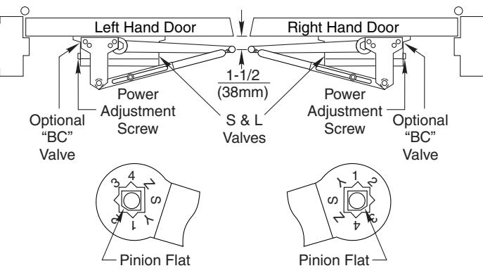
- •Mount soffit plate to frame.
- Install main arm onto closer pinion shaft. Rotate pinion 45° toward hinge edge of door to align main arm letter "3" (right hand) or "2" (left hand) with pinion flat. Fasten with arm screw.
- Fasten forearm to soffit plate. Adjust forearm length to set arm elbow about 1-1/2" (38mm) from door when connected to main arm. Tighten forearm screw.
- Screw pinion cap onto pinion shaft by hand or with a Phillips screw driver - DO NOT OVER TIGHTEN. Skip this step if optional cover is used.
- •Adjust closer. See Closer Adjustments on Pages 2 and 3.
Cover
Thread in screws before mounting closer. Leave enough gap between the head of the screw and the closer to slide the cover on. Slide the cover over the closer and secure the mounting screws after the closer has been mounted and adjusted.
Typical Installation
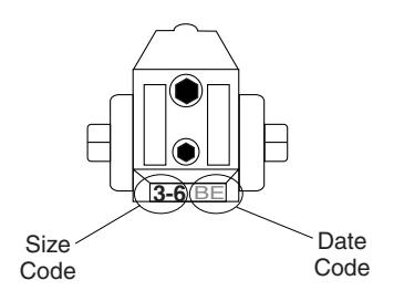
To identify your model:
3=1603BC 1-6=1601 4=1604BC

3000 Highway 74 East • Monroe, NC 28112 Tel: (800)-438-1951 ext. 6030 www.nortondoorcontrols.com support.aadcg@assaabloy.com