Norton 1600SS & 1601SS Corrosion Resistant Series Non Hold Open Closers Installation Instructions
Open the original PDF document
View PDF

ASSA ABLOY
Installation Instructions Corrosion Resistant Series
1600SS Series Sized Closers 1601SS Series Multi-Sized Closers Non Hold Open Models
Sized (Sizes 3, 4)
Multi-Sized (Sizes 1-6)
1603BCSS 1604BCSS
1601SS
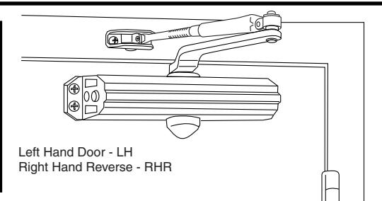
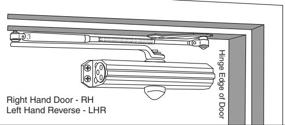
Regular Arm Installation
Closer on door on hinge (pull) side of door
See Page 2
An incorrectly installed or improperly
property damage or personal injury. These instructions should be followed
adjusted door closer can cause
to avoid the possibility of misapplication or misadjustment.
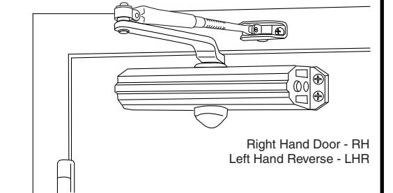
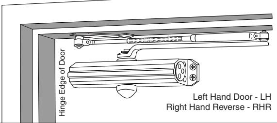
Top Jamb Installation
Closer on frame on opposite to hinge (push) side of door
See Page 3
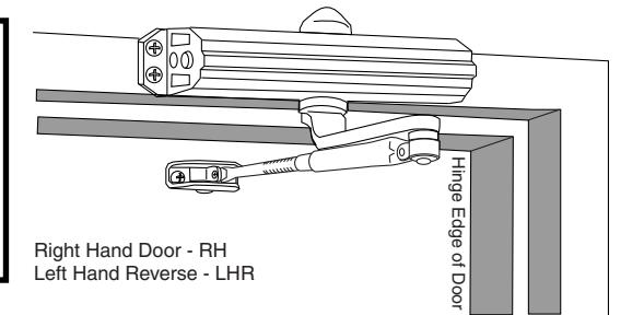
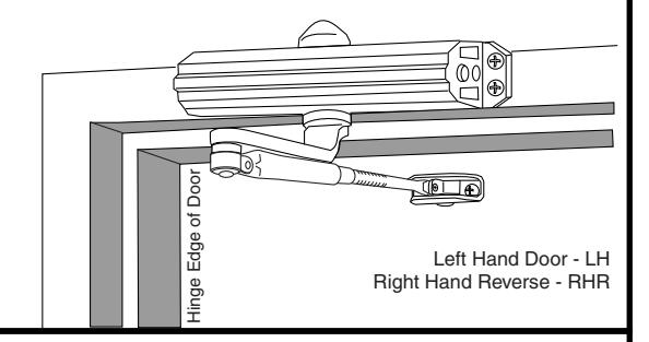
Parallel Arm Installation
Closer on door on opposite to hinge (push) side of door
See Page 4
NOTE: For special applications a separate door and frame preparation template is packed with these instructions Use this instruction sheet for installation sequence and closer adjustments only
- It is recommended that the door on which the door closer will be installed be hung on ball bearing hinges. Door must swing freely
- A separate door stop, supplied by others, is recommended to prevent damage to the door closer, closer arm, or to the door, frame or adjacent walls.
- Door and Frame must be properly reinforced, or use of special fasteners employed, to prevent the mounting screws from pulling out.
- · All dimensions are given in inches with corresponding metric dimensions (mm) in parenthesis.
- · Door closer must not be installed on the exterior side of doors in exterior walls.
Regular Arm Installation


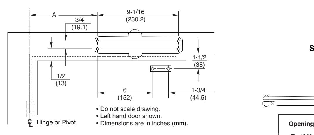
• Dimensions are in inches (mm).
Installation Sequence
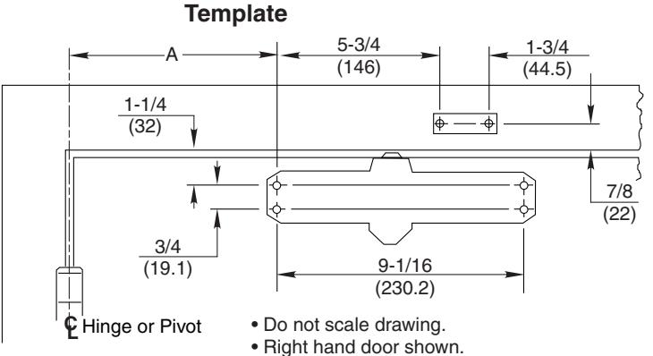
- Select door opening angle using template above. Mark 4 holes on door for closer and 2 holes on frame face for arm shoe.
- Prepare door and frame for fasteners See "Preparation for Fasteners" below.
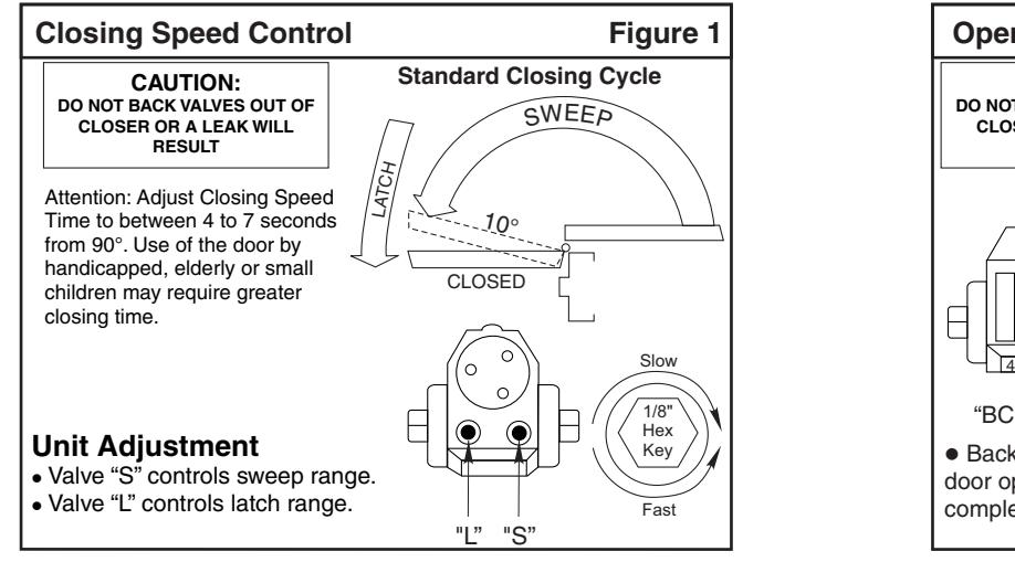
- 1601SS Models Only. Set approximate closing power using "Power Adjustment Chart" below right.
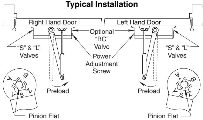
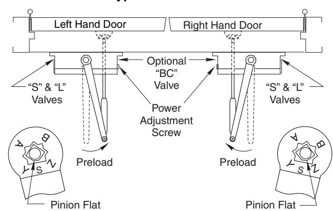
- Install closer with "S" and "L" adjustment valves toward hinge edge of door.
- Disassemble arm at elbow (forearm screw).
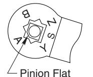
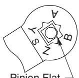
- Install main arm onto closer pinion shaft, indexing main arm mark "S" with pinion flat as shown at right.
- Reassemble arm by adjusting the length of the forearm, to be perpendicular (at 90° angle) to the door when connected to the main arm (at the preload position).
| 4 | ||||||
|---|---|---|---|---|---|---|
| Opening | Dimension A | |||||
| Opening | inches | mm | 1 | | |||
| To 100° | 7 | 178 | 1 | |||
| 101° to 120° | 6 | 152 | ||||
| 121° to 180° | 3-1/2 | 89 | 1 | |||
| * Door/Wall/Hardware/Jamb conditions permitting | ||||||
| ζ | Typical | Install | ation | |||
| Right Hand D | Door | \/ L | eft Hand Do | or | ||
|
ptional —
"BC" |
1 | |||||
Side Elevation
- Screw pinion cap onto pinion shaft by hand or with a Phillips screw driver -DO NOT OVER TIGHTEN.
- · Adjust closer.
| Preparation for Fasteners | ||||||
|---|---|---|---|---|---|---|
| Fasteners Door or Frame Drill-Sizes | ||||||
| Standard | Aluminum or Metal | No drill required | ||||
|
1/4" - 20 machine
screw |
Wood |
3/16" (4.30 mm)
Pilot hole required |
||||
| Metal |
Drill: #7 (0.201" dia.)
Tap: 1/4" - 20 |
|||||
| Optional | Sleeve nuts and bolts |
Hollow
Metal |
9/32" (7 mm) through;
3/8" (9.5 mm) door face opposite to closer |
|||
| Aluminum or Wood | 3/8" (9.5 mm) through | |||||
| Through-bolts and grommet-nuts | All |
9/32" (7 mm);
3/8" (9.5 mm) dia. x 3/8" (9.5 mm) deep on door opposite to closer |
||||
| Adjustment Chart | Number of Turns Required | ||||||||
|---|---|---|---|---|---|---|---|---|---|
| Π| TYPE | MAXIMUM DOOR SIZE | |||||||
| DOOR |
OF
INST. |
* |
34"
(0.85M) |
36"
(0.90M) |
40"
(1.00M) |
44"
(1.10M) |
48"
(1.20M) |
||
| INTERIOR |
Regular Arm
Top Jamb |
TURNS OF
OWER T WRENCH |
2 | 4 | 6 | 10 | 12 | ||
| 160155 | Parallel Arm |
360° TURNS OF
716 POWER TMENT WRENCI |
3 | 5 | 8 | 11 | 14 | ||
| 160 | EXTERIOR |
Regular Arm
Top Jamb |
n W in | 3 | 5 | 8 | 11 | 14 | |
| EXTE | Parallel Arm | FULL | 5 | 8 | 11 | 16 | 19 | ||
| *30 FULL (360°) TURNS MAXIMUM AVAILABLE = 8 Turns As Shipped | |||||||||
Top Jamb Installation
Template

Installation Sequence
- · Select door opening angle using template above. Mark 4 holes on frame face for closer and 2 holes on door for arm shoe.
- · Prepare door and frame for fasteners. See "Preparation for Fasteners" at bottom of Page 2.
- · 1601SS Models Only. Set approximate closing power using "Power Adjustment Chart" at bottom of Page 2.
- · Install closer with "S" and "L" adjustment valves toward hinge edge of door.
- · Remove forearm from arm assembly. Mount arm shoe to door.
- · Install main arm onto closer pinion shaft, indexing main arm mark "S" with pinion flat as shown at right.
- · Reassemble arm by adjusting the length of the forearm to be perpendicular (at a 90° angle) to the door, when connected to the main arm (at the preload position).
- · Screw pinion cap onto pinion shaft by hand or with a Phillips screw driver - DO NOT OVER TIGHTEN.
- · Adjust closer.
Side Elevation
| Dimension A | |||
|---|---|---|---|
| inches | mm | ||
| To 100° | 7 -1/2 | 191 | |
| 101° to 120° | 6 | 152 | |
| 121° to 180° | 3-1/2 | 89 | |
|
* Door/Wall/Hardware/Jamb
conditions permitting |
|||
Typical Installation
Door Closer Adjustment (Continued)
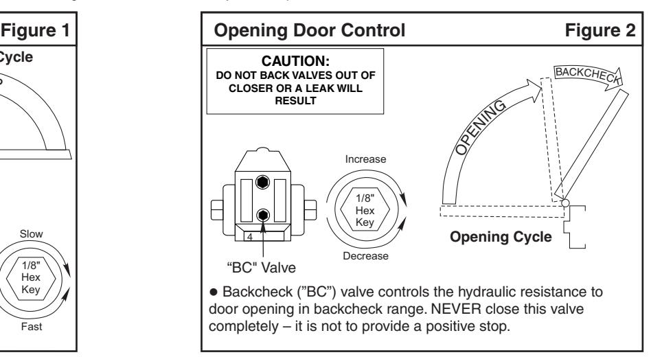
"DA" suffix (Delayed Action) is an optional feature.
A separate instruction will be packed with these instructions showing valve locations and adjustment procedures.
Parallel Arm Installation
Template
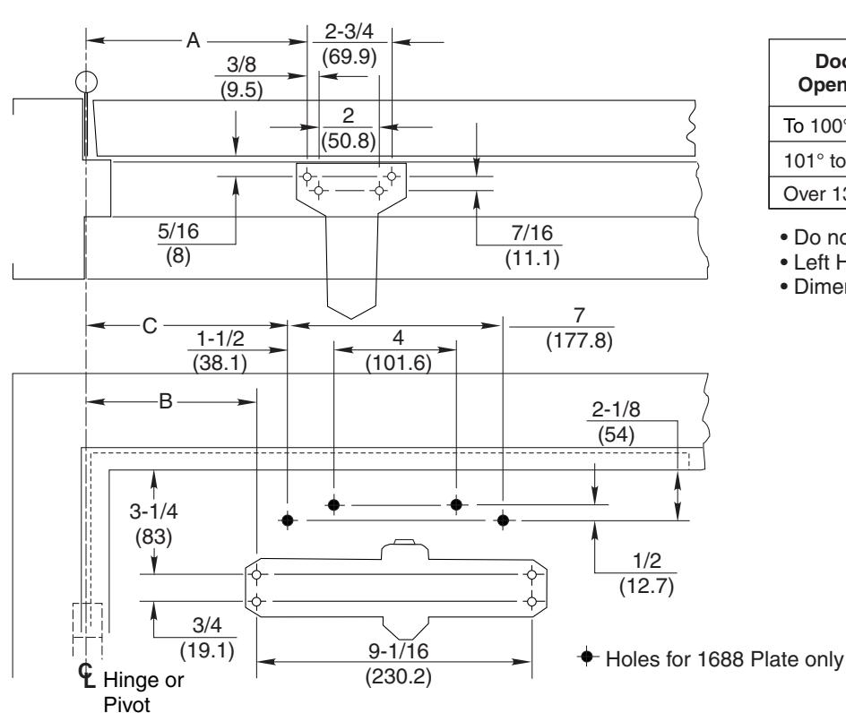
| Door | Dimension A | Dimension B | Dimension C | |||
|---|---|---|---|---|---|---|
| Opening | Inches | mm | Inches | mm | Inches | mm |
| To 100° | 9-1/4 | 235 | 7-5/8 | 194 | 8-5/8 | 219 |
| 101° to 130° | 7-3/4 | 197 | 6-1/8 | 156 | 7-1/8 | 181 |
| Over 131° | 5-3/4 | 146 | 4-1/8 | 105 | 5-1/8 | 130 |
- · Do not scale drawing
- Left Hand shown
- Dimensions are in inches (mm)
Side Elevation
Installation Sequence
- Select door opening angle using template above. Mark 4 holes on door for closer or 1688 Drop Plate and 4 holes on frame for soffit plate.
- •Prepare door and frame for fasteners. See "Preparation for Fasteners" bottom of Page 2.
- Mount soffit plate to frame.
- 1601SS Models Only. Set approximate closing power using "Power Adjustment Chart" at bottom of Page 2.
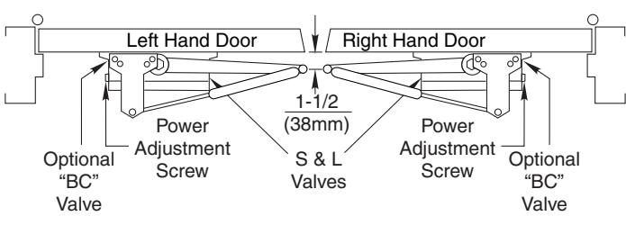
- •Mount closer to door with 2 regulating valves toward lock edge of door.
- Install main arm onto closer pinion shaft. Rotate pinion 45° toward hinge edge of door to align main arm letter "B" (right hand) or "A" (left hand) with pinion flat. Fasten with main arm screw.
- Fasten forearm to soffit plate. Adjust forearm length to set arm elbow about 1-1/2" (38mm) from door when connected to main arm.
- · Screw pinion cap onto pinion shaft by hand or with a Phillips screw driver - DO NOT OVER TIGHTEN.
- •Adjust closer. See closer adjustments on Pages 2 and 3.
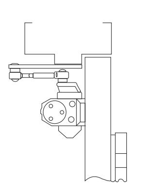
Typical Installation
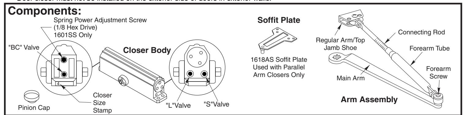
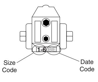
To identify your model:
1-6=1601SS
3=1603BCSS
4=1604BCSS

www.nortondoorcontrols.com support.aadcg@assaabloy.com