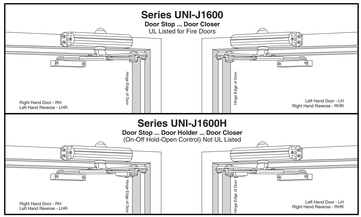
Norton 1600 Series Door Closer UNI-J1600BC UNI-J1601 UniTrol Non-Hold Open and Hold Open Installation Instructions
Open the original PDF document
View PDF

Installation Instructions UniTrol®
UNI-J1600BC Series Sized Closers UNI-J1601 Series Multi-Sized Closers
Non Hold Open (UL Listed) Hold Open (H) (Not UL Listed):
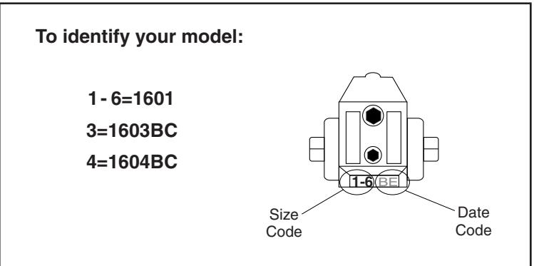
Models
Sized (Sizes 3, 4)
Multi-Sized (Sizes 1 thru 6)
UNI-J1603BC(H) UNI-J1604BC(H)
UNI-J1601(H)
An incorrectly installed or improperly adjusted door closer can cause property damage or personal injury. These instructions should be followed to avoid the possibility of misapplication or misadjustment.
NOTE: For special applications a separate door and frame preparation template is packed with these instructions
Use this instruction sheet for installation sequence and closer adjustments only
- It is recommended that the door on which the door closer will be installed be hung on ball bearing hinges. Door must swing freely
- Door and Frame must be properly reinforced, or use of special fasteners employed, to prevent the mounting screws from pulling out.
- All dimensions are given in inches with corresponding metric dimensions (mm) in parenthesis.
Hollow-Metal or Wood Openings


| Openi | ng | Dimension A | ||
|---|---|---|---|---|
| Hold Open | Stop | inches | mm | |
| 85° | 90° | 9-1/8 | 232 | |
| 90° | 95° | 8-3/8 | 213 | |
| 95° | 100° | 7-3/4 | 197 | |
| 100° | 105° | 7-3/8 | 187 | |
| 105° | 110° | 6-3/4 | 171 | |
| 110° | 115° | 6-1/2 | 165 | |
Installation Sequence
- This page for installation on hollow-metal or wood. For aluminum doors and frame use Page 3.
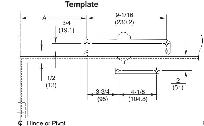
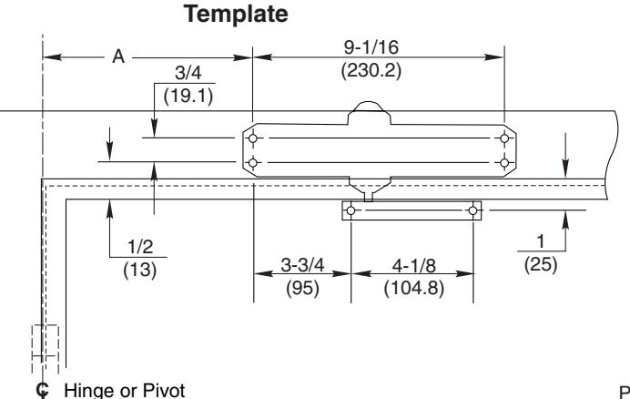
- Select door opening angle using template above. Mark 4 holes on frame face for closer and 2 holes on door for arm foot.
- Prepare door and frame for fasteners. See "Preparation for Fasteners" below.
- 1601 Models Only. Set approximate closing power using "Power Adjustment Chart" at bottom of Page 3.
- Install closer to frame face with 2 regulating valves toward hinge edge of door.
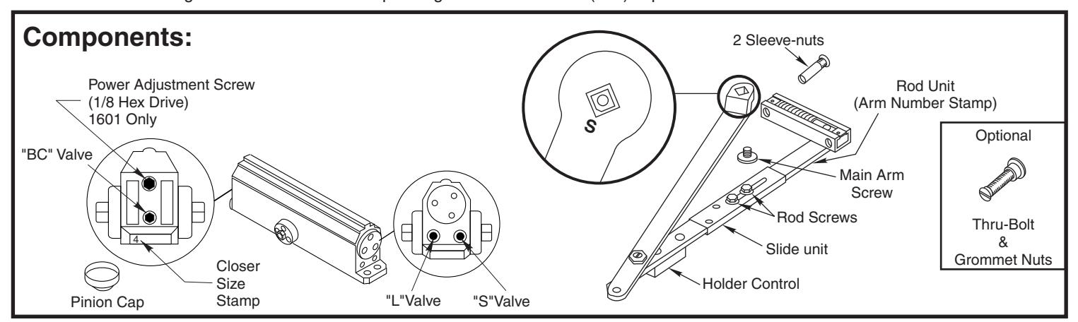
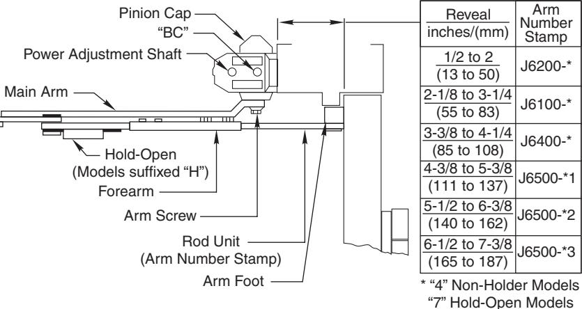
- · Remove rod unit from arm assembly.
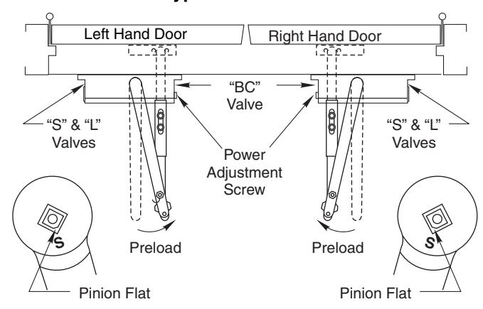
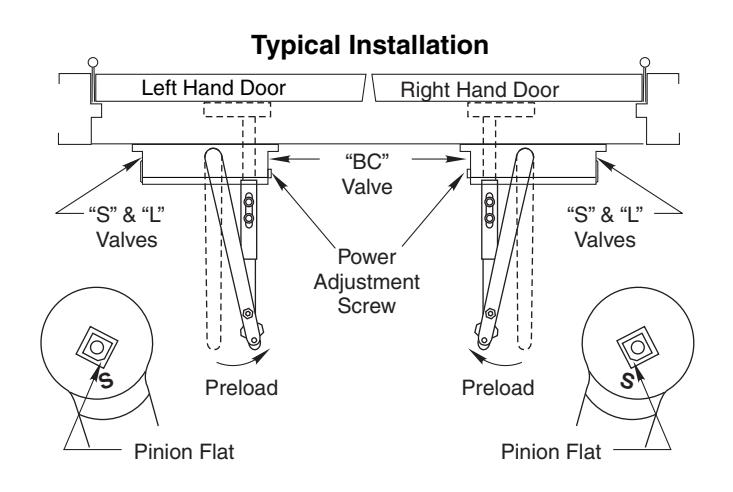
- Install main arm onto closer pinion shaft, indexing main arm mark "S" with pinion flat as shown at right. Fasten with arm screw.
- Mount arm foot to door. Position foot with rod on top and spring toward hinge.
- Reassemble arm. Adjust forearm perpendicular (at a 90° angle) to the door. Install and tighten rod screws.
- Screw pinion cap onto pinion shaft by hand or with a Phillips screw driver - DO NOT OVER TIGHTEN.
- · Adjust closer.
"4" Non-Holder Models "7" Hold-Open Models
Typical Installation
| Preparation for Fasteners | |||||
|---|---|---|---|---|---|
| Fasteners | Door or Frame | Drill-Sizes | |||
| Colf Drilling Corou |
Aluminum
or Metal |
No drill required | |||
| Self-Drilling Screw | Wood |
3/16" (4.30 mm)
Pilot hole required |
|||
| 1/4" - 20 machine screw | Metal |
Drill: #7 (0.201" dia.)
Tap: 1/4" - 20 |
|||
| Sleeve nuts and bolts |
Hollow
Metal |
9/32" (7 mm) through;
3/8" (9.5 mm) door face opposite to closer |
|||
|
Aluminum
or Wood |
3/8" (9.5 mm) through | ||||
80-9316-2534-020 Rev 1
Aluminum Openings


| Opening | Dimension A | |||
|---|---|---|---|---|
| Hold Open | Stop | inches | mm | |
| 85° | 90° | 9-1/8 | 232 | |
| 90° | 95° | 8-3/8 | 213 | |
| 95° | 100° | 7-3/4 | 197 | |
| 100° | 105° | 7-3/8 | 187 | |
| 105° | 110° | 6-3/4 | 171 | |
| 110° | 115° | 6-1/2 | 165 | |
Installation Sequence
- This page for installation on aluminum doors and frames only.
- Select door opening angle using template above. Mark 4 holes on frame face for closer and 2 holes on door for arm foot.
- Prepare door and frame for fasteners. See "Preparation for Fasteners" at bottom of Page 2.
- 1601 Models Only. Set approximate closing power using "Power Adjustment Chart" below.
- Install closer to frame face with 2 regulating valves toward hinge edge of door.
- · Remove rod unit from arm assembly.
- Install main arm onto closer pinion shaft, indexing main arm mark "S" with pinion flat as shown at right. Fasten with arm screw.
- Mount arm foot to door. Position foot with rod on bottom and spring toward hinge.
- Reassemble arm. Adjust forearm perpendicular (at a 90° angle) to the door. Install and tighten rod screws.
- Screw pinion cap onto pinion shaft by hand or with a Phillips screw driver - DO NOT OVER TIGHTEN.
- · Adjust closer.
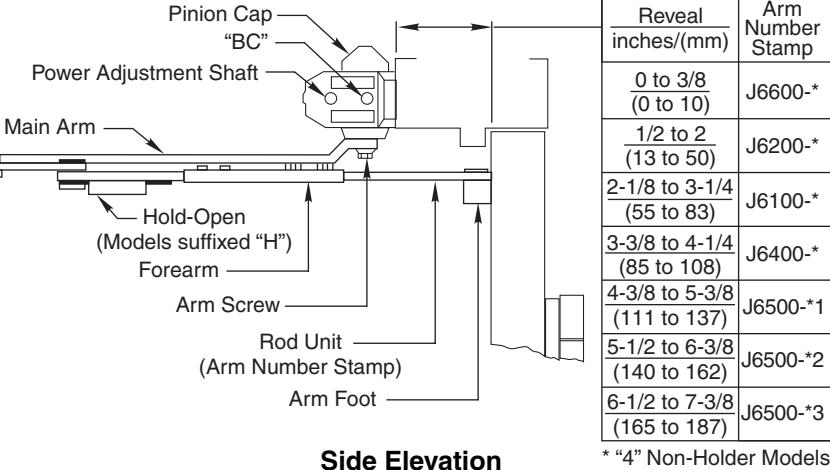
Side Elevation
| Power Adjustment Chart | ||||||||
|---|---|---|---|---|---|---|---|---|
| TOP JAMB | al. | MAXIMUM DOOR SIZE | ||||||
| DOOR | INSTALLATION | * |
34"
(0.85 m) |
36"
(0.9 m) |
40"
(1 m) |
44"
(1.1 m) |
48"
(1.2 m) |
|
| INT | 1601 |
FULL 360° TURNS
OF POWER ADJUSTMENT SHAFT |
2 | 4 | 6 | 10 | 12 | |
| EXT | 3 | 5 | 8 | 11 | 14 | |||
| *30 -360° TURNS MAXIMUM AVAILABLE | ||||||||
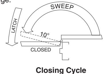
Unit Adjustment
Closing Speed Control
• Valve "S" controls Sweep Range.
• Valve "L" controls Latch Range.
Attention: Adjust Closing Speed Time to between 4 to 7 seconds from 90°. Use of the door by handicapped, elderly or small children may require greater closing time. ADA code requires that door take at least 3 seconds to close from 70° of door opening to within 3" (75mm) of the closed position.
NOTE: By law the Americans with Disabilities Act (ADA) may require that door closer installation comply with accessability guidelines.
"S"Valve
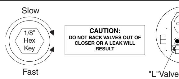
Opening Door Control • Backcheck ("BC") valve controls the hydraulic resistance to door opening in backcheck range. NEVER close this valve completely – it is not to provide a positive stop. | CAUTION: | Do NOT BACK VALVES OUT OF CLOSER OR A LEAK WILL RESULT | |-----------------------------------
Figure 1
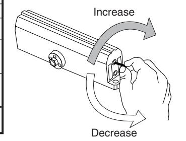
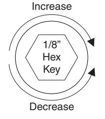
Closing Power Control Increase Increase Increase Decrease
Opening Cycle

Decrease
| Power Adjustment Chart | |||||||
|---|---|---|---|---|---|---|---|
| TOP JAMB | ala. | MAXIMUM DOOR SIZE | |||||
| DOOR | INSTALLATION | * |
34"
(0.85 m) |
36"
(0.9 m) |
40"
(1 m) |
44"
(1.1 m) |
48"
(1.2 m) |
| INT | — 1601 |
)°TURNS
)WER TMENT |
2 | 4 | 6 | 10 | 12 |
| EXT |
HS
SDA JO SH YOL SH/ |
3 | 5 | 8 | 11 | 14 | |
Adjust as required. Product is shipped at approximately 8 turns of spring adjust.
*30 -360° TURNS MAXIMUM AVAILABLE
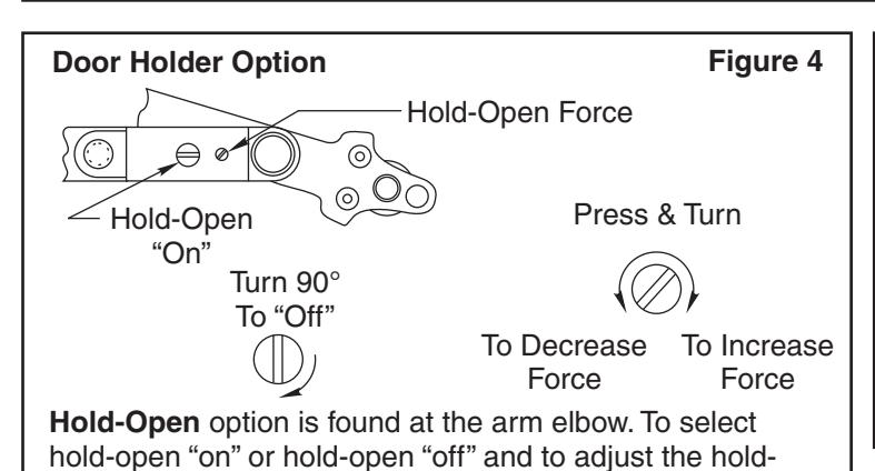

open force ... use screwdriver as illustrated.