Norton 1600 Series Door Closer UNI-1600BC UNI-1601 Unitrol Non-Hold Open and Hold Open Installation Instructions
Open the original PDF document
View PDF

ASSA ABLOY
Installation Instructions
UniTrol® Door Controls UNI-1600BC Series Sized Closers UNI-1601 Series Multi-Sized Closers
An incorrectly installed or improperly adjusted door closer can cause property damage or personal injury. These instructions should be followed to avoid the possibility of misapplication or misadjustment.
Non Hold Open (UL Listed) Hold Open (H) (Not UL Listed) Models:
Sized (Sizes 3, 4)
Multi-Sized (Sizes 1 thru 6)
UNI-1603BC(H) UNI-1604BC(H)
UNI-1601(H)
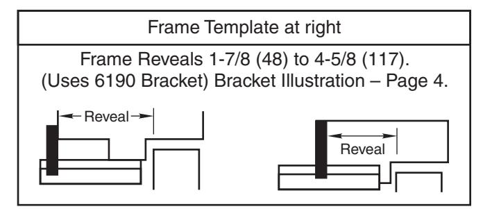
Standard Frame Installation
1-7/8 to 4-5/8 Frame Reveals (Uses 6190 Bracket). Bracket illustration page 4. See Page 2
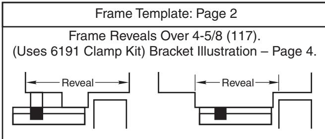
Deep Frame Installation
Frame Reveals Over 4-5/8 (Uses 6191 Clamp Kit). Bracket illustration page 4.
See Page 3
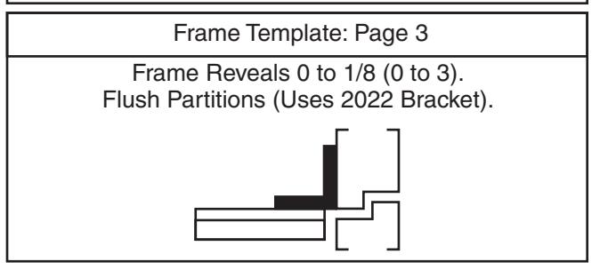
Flush Transom Installation
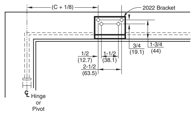
Flush Partitions (Uses 2022 Bracket). Bracket illustration page 4.
See Page 4
NOTE: For special applications a separate door and frame preparation template is packed with these instructions Use this instruction sheet for installation sequence and closer adjustments only
- It is recommended that the door on which the door closer will be installed be hung on ball bearing hinges. Door must swing freely
- Door and Frame must be properly reinforced, or use of special fasteners employed, to prevent the mounting screws from pulling out.
- All dimensions are given in inches with corresponding metric dimensions (mm) in parenthesis.
Template Information
- Door template is typical for all installations.
- Frame template must be selected according to frame reveal:

ASSA ABLOY
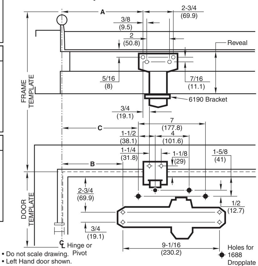
Door Template Typical for All Installations Frame Template for 1-7/8 to 4-5/8 Reveals
| Preparation for Fasteners | ||||||||
|---|---|---|---|---|---|---|---|---|
| Fasteners | Door or Frame | Drill-Sizes | ||||||
| Self-Drilling Screw | Aluminum or Metal | No drill required | ||||||
| Wood |
3/16" (4.30 mm)
Pilot hole required |
|||||||
| 1/4" - 20 machine screw | Metal |
Drill: #7 (0.201" dia.)
Tap: 1/4" - 20 |
||||||
| Sleeve nuts and bolts |
Hollow
Metal |
9/32" (7 mm) through;
3/8" (9.5 mm) door face opposite to closer |
||||||
| Aluminum or Wood | 3/8" (9.5 mm) through | |||||||
| Power Adjustment Chart | ||||||||||
|---|---|---|---|---|---|---|---|---|---|---|
| PARALLEL ARM | * | MAXIMUM DOOR SIZE | ||||||||
| DOOR | INSTALLATION | ^ |
34"
(0.85 m) |
36"
(0.9 m) |
40"
(1 m) |
44"
(1.1 m) |
48"
(1.2 m) |
|||
| INT | 1601 |
*TURNS
WER MENT FT |
3 | 5 | 8 | 11 | 14 | |||
| EXT | 1001 |
FULL 360
OF PC ADJUS SHA |
5 | 8 | 11 | 16 | 19 | |||
| *30 -360° TURNS MAXIMUM AVAILABLE | ||||||||||
| Dimensions for Doors 28" to 32" Wide | |||||||||
|---|---|---|---|---|---|---|---|---|---|
| Opening | Dimension A | Dimension B | Dimension C | ||||||
| Hold Open | Stop | Inches | mm. | Inches | mm. | Inches | mm. | ||
| 85° | 90° | 10-1/2 | 267 | 8-5/8 | 219 | 9-5/8 | 244 | ||
| 90° | 95° | 9-3/4 | 248 | 8 | 203 | 9 | 229 | ||
| 95° | 100° | 9-1/4 | 235 | 7-1/2 | 191 | 8-1/2 | 216 | ||
| 100° | 105° | 8-7/8 | 225 | 7-1/8 | 181 | 8-1/8 | 206 | ||
| 105° | 110° | 8-1/2 | 216 | 6-3/4 | 171 | 7-3/4 | 197 | ||
| 110° | 115° | 8-1/8 | 206 | 6-3/8 | 162 | 7-3/8 | 187 | ||
| Dimensions for Doors 33" to 41" Wide | |||||||||
|---|---|---|---|---|---|---|---|---|---|
| Openin | Dimension A | Dimension B | Dimension C | ||||||
| Hold Open | Stop | Inches | Inches mm. | mm. | Inches | mm. | |||
| 85° | 90° | 12-5/8 | 321 | 11 | 279 | 12 | 305 | ||
| 90° | 95° | 12 | 305 | 10-3/8 | 264 | 11-3/8 | 289 | ||
| 95° | 100° | 11-3/8 | 289 | 9-3/4 | 248 | 10-3/4 | 273 | ||
| 100° | 105° | 10-7/8 | 276 | 9-1/4 | 235 | 10-1/4 | 260 | ||
| 105° | 110° | 10-3/8 | 264 | 8-3/4 | 222 | 9-3/4 | 248 | ||
| 110° | 115° | 10 | 254 | 8-3/8 | 213 | 9-3/8 | 238 | ||
| Dimensions for Doors 42" to 48" Wide | ||||||||||
|---|---|---|---|---|---|---|---|---|---|---|
| Openin | Dimension A | Dimension B | Dimension C | |||||||
| Hold Open | Stop | Inches | mm. | Inches | mm. | Inches | mm. | |||
| 85° | 90° | 15 | 381 | 13-1/4 | 337 | 14-1/4 | 362 | |||
| 90° | 95° | 14-1/4 | 362 | 12-1/2 | 318 | 13-1/2 | 343 | |||
| 95° | 100° | 13-5/8 | 346 | 11-7/8 | 302 | 12-7/8 | 327 | |||
| 100° | 105° | 13 | 330 | 11-1/4 | 286 | 12-1/4 | 311 | |||
| 105° | 110° | 12-1/2 | 318 | 10-3/4 | 273 | 11-3/4 | 298 | |||
| 110° | 115° | 12 | 305 | 10-1/4 | 260 | 11-1/4 | 286 | |||
• Dimensions are in inches (mm).
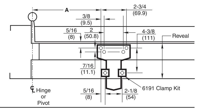
Frame Template for Reveals Over 4-5/8 Door Template on Page 2

Frame Template for Flush Partitions Door Template on Page 2
Installation Sequence
! Read Front Page.
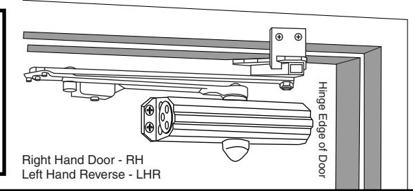
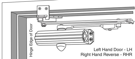
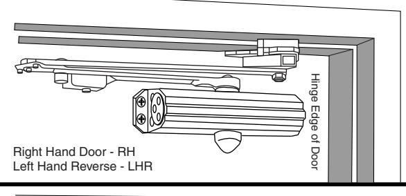
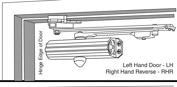
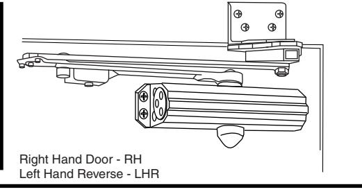
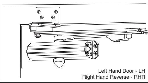
Installations and component identification are on this page. Arm assembly must be correct for width of door, see chart.
! Select Correct Door and Frame Template Combination.
Follow "Template Information" on Page 2 or Pages 2 and 3.
! Mark Location of Mounting Holes.
Use dimensions for hold-open or door stop angle desired. Mark position of 4 holes on door for closer (or drop plate) and 6 holes on frame for soffit plate (or 4 for 2022 angle bracket).
! Prepare Holes for Fasteners.
See "Preparation for Fasteners" chart on Page 2.
! UNI1601 Model Only. Set approximate closing power using "Power Adjustment Chart" at bottom of Page 2.
Mount Closer to Door.
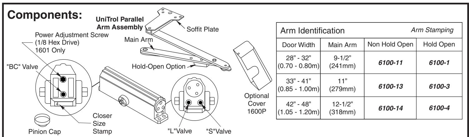
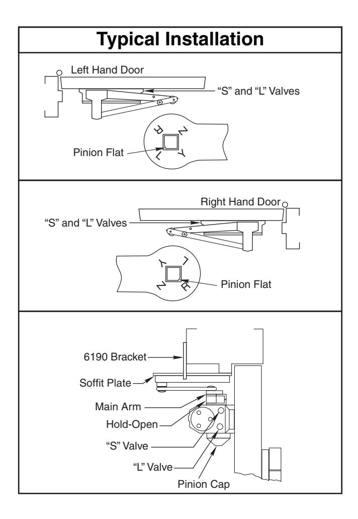
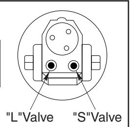
Drop Plate first, if used. Place end with "S" and "L" valves toward the lock edge of the door. If using optional cover see "Cover" instructions at bottom of Page 4.
Mount Arm to Frame.
Fasten soffit plate (or 2022 angle bracket if flush partition) to frame. Mount 6190 bracket or 6191 clamps to reinforce soffit plate.
! Install Arm on Pinion Shaft.
Close valves "S" and "L". Rotate pinion over 45° to align main arm letter "R" (right hand) or "L" (left hand) with pinion flat. Fasten with arm screw. See "Typical Installation" figure above right. Re-open valves "S" and "L".
Screw pinion cap onto the pinion shaft by hand or with a Phillips screw driver - DO NOT OVER TIGHTEN. Skip this step if optional cover is used.
Adjust Closer.
See "Unit Adjustment" on Page 4.
Unit Adjustment
Closing Speed Control
• Valve "S" controls Sweep Range.
• Valve "L" controls Latch Range.
Attention: Adjust Closing Speed Time to between 4 to 7 seconds from 90°. Use of the door by handicapped, elderly or small children may require greater closing time. ADA code requires that door take at least 3 seconds to close from 70° of door opening to within 3" (75mm) of the closed position.
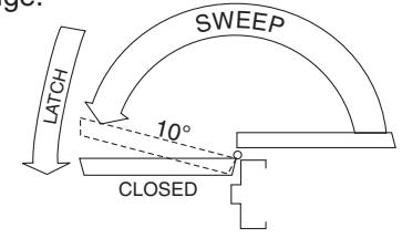
Closing Cycle
NOTE: By law the Americans with Disabilities Act (ADA) may require that door closer installation comply with accessability guidelines.
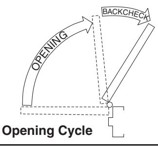
Opening Door Control
Figure 2
Figure 1
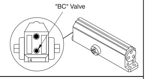
• Backcheck ("BC") valve controls the hydraulic resistance to door opening in backcheck range. NEVER close this valve completely – it is not to provide a positive stop.
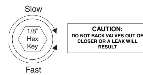
CAUTION: DO NOT BACK VALVES OUT OF CLOSER OR A LEAK WILL RESULT
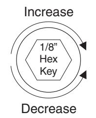
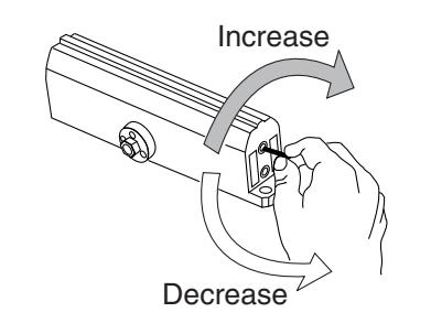
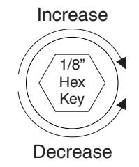
Closing Power Control
Figure 3
| Power Adjustment Chart | |||||||||
|---|---|---|---|---|---|---|---|---|---|
| PARALLEL ARM | ماله | MAXIMUM DOOR SIZE | |||||||
| DOOR | INSTALLATION | * |
34"
(0.85 m) |
36"
(0.9 m) |
40"
(1 m) |
44"
(1.1 m) |
48"
(1.2 m) |
||
| INT | 1601 |
"TURNS
WER TMENT |
3 | 5 | 8 | 11 | 14 | ||
| EXT | 1001 |
FULL 360
OF PC ADJUS' SH/ |
5 | 8 | 11 | 16 | 19 | ||
| *30 -360° TURNS MAXIMUM AVAILABLE | |||||||||
Adjust as required. Product is shipped at approximately 8 turns of spring adjust.
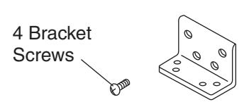
Bracket Illustrations
Standard 6190 Bracket
Deep Reveal Option Spacer Block Clamps
2 Clamp Screws No. 6191 Reinforcing Kit
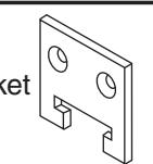
Flush Partition Option
No. 2022 Bracket
Cover (Optional Cover 1600P)
Thread in screws before mounting closer. Leave enough gap between the head of the screw and the closer to slide the cover on. Slide the cover over the closer and secure the mounting screws after installation is complete.
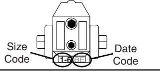
To identify your model:
1-6=1601
3=1603BC 4=1604BC
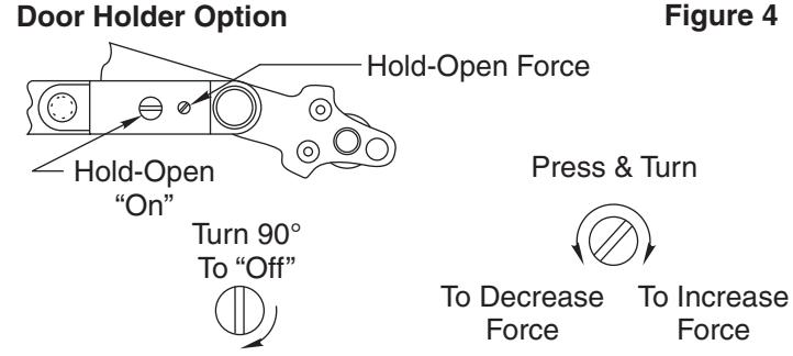
Hold-Open option is found at the arm elbow. To select hold-open "on" or hold-open "off" and to adjust the hold-open force ... use screwdriver as illustrated.

ASSA ABLOY
3000 Highway 74 East • Monroe, NC 28112 Tel: (800)-438-1951 ext. 6030 www.nortondoorcontrols.com support.aadcg@assaabloy.com
ASSA ABLOY, the global leader in door opening solutions