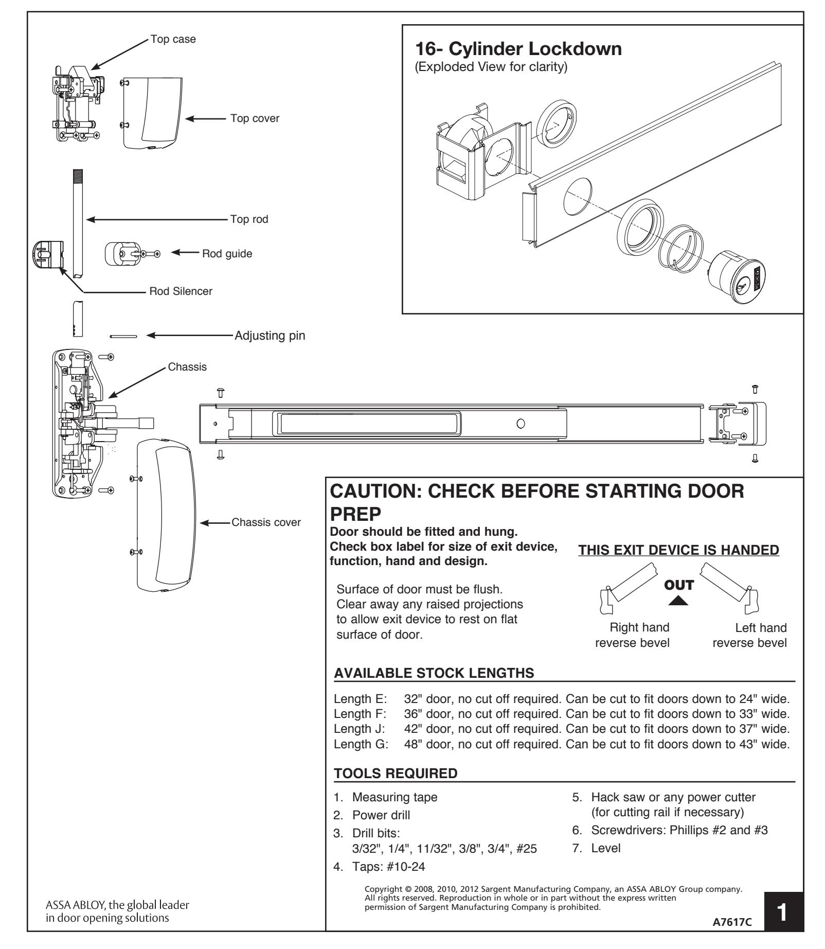
NB8700 & 12-NB8700 Series Surface Vertical Rod Exit Device Installation Instructions
Open the original PDF document
View PDFINSTALLATION INSTRUCTIONS NB8700 & 12-NB8700 Series Surface Vertical Rod Exit Device
FOR INSTALLATION ASSISTANCE CALL SARGENT AT 1-800-727-5477 • www.sargentlock.com
FIRST
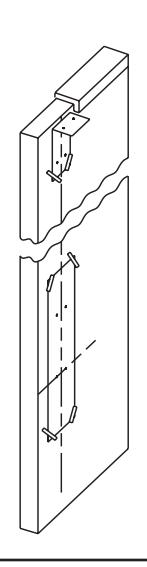
DETERMINING CENTER LINES AND PREP DOOR
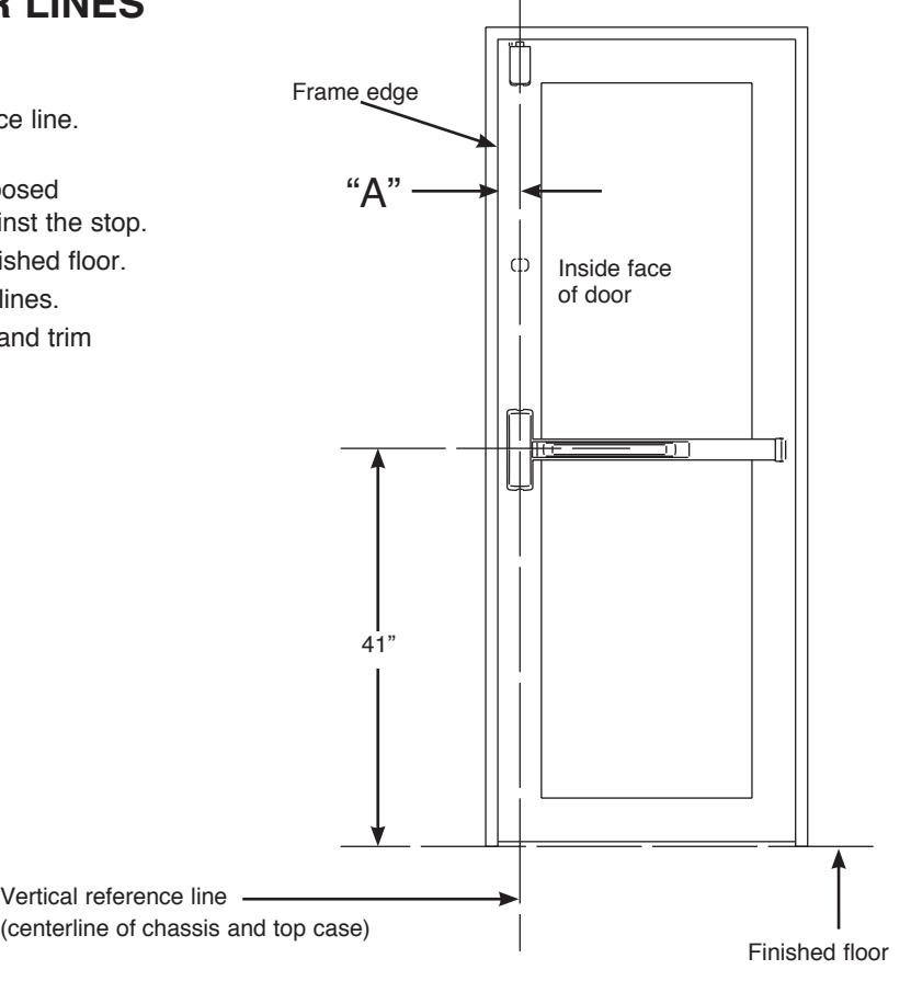
- 1. Determine dimension "A" to locate vertical reference line. If lock stile is 4-1/2" wide or wider, "A" is 2-3/4". If lock stile is less than 4-1/2", "A" is 1/2 of the exposed width of the lock stile when the door is closed against the stop.
- 2. Standard rail centerline height is 41" above the finished floor.
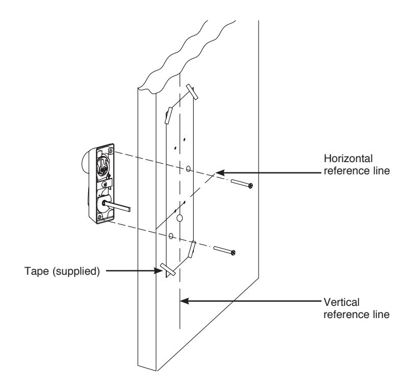
- 3. Tape templates on inside of door along reference lines.
- 4. Spot and drill all holes from inside of door for exit and trim being used.
- 5. For ET Controls, see templates supplied for trim.
ATTACHING NB-300 AUXILIARY CONTROL (IF USED)
Note: This section is used only to install NB-300 auxiliary control.
Note: NB-300 must be installed prior to installing exit device on door.
1. Verify that the required 3 holes for NB-300 auxiliary control from template A7616 are drilled and c'sunk. These holes should be located from the inside of the door.
Note: Verify that NB-300 auxiliary control is handed correctly. The top of the turn must rotate toward door hinges.
- 2. Position NB-300 control on the outside of the door with the cylinder up.
- 3. Throughbolt the NB-300 control to the door with (2) # 10-24x2" long flat head screws and tighten firmly.
- 4. Center case chassis is located with NB-300's flat spindle engaging lower hub of center case chassis

SECOND
ATTACHING CENTER CHASSIS AND 700 SERIES ET CONTROL TRIM (IF USED)
ATTACHING THE CHASSIS
1. Secure chassis to door with (4) #10 flat head screws (A) using the four corner holes of the chassis and the appropriate screws (Wood/Metal).
NOTE: See instruction sheet A6374 for ET details (changing hands, etc).
ATTACHING ET CONTROL
- 2. To install ET control, first loosen 2 screws (B) holding the tube support (C) and adjusting tube (D) on chassis. Slide off to remove the tube support (C).
- 3. Slide ET control spindle (E) into the lower chassis hub (F) and position ET control against the door.
- 4. Throughbolt ET control to chassis with (2) 1/4-20 flat head screws (G).
- 5. Re-attach adjusting tube (D) and tube support (C) with 2 screws (B).
- 6. Attach 646 top strike using holes marked in the first step with (2) #12-24 flat head screws.
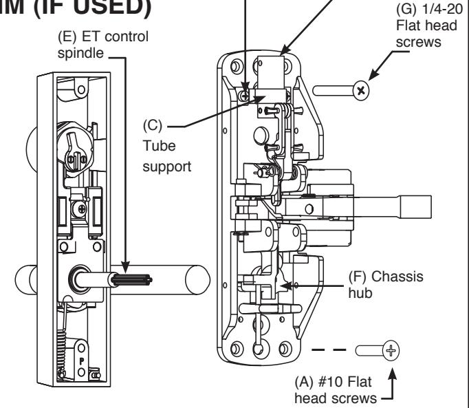
(B) Oval head screws
(D) Adjusting tube
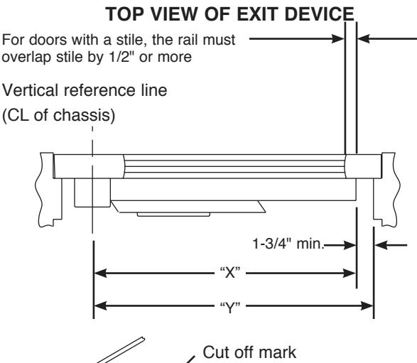
THIRD PREPARING AND INSTALLING RAIL ASSEMBLY
Check box label.
The following prefixes are provided "factory cut" to size: AL-, 56- and 58.
If cutting is required continue with step "A".
If cutting is not required proceed to step "B".
A Determine cut off dimension "X" by subtracting 1-3/4" from dimension "Y".
- 1. Depress push rail and cut off at mark.
- 2. Cut must be straight.
- 3. For (43-) flush end cap use cutting guide provided.
- 4. Remove sharp edges with file.
B
- 1. Push lift arm toward the door and slide rail onto chassis and over the lift arm.
- 2. Attach rail assembly to chassis with two (2) #8-32 truss head machine screws (H).
NOTE: Do NOT tighten screws.
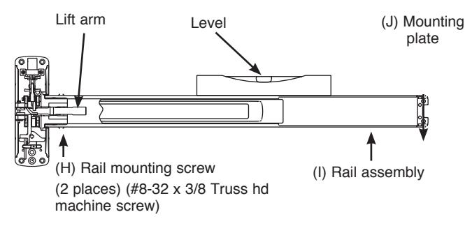
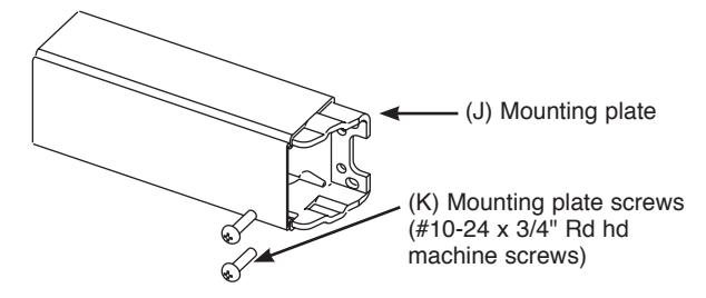
- 3. Level rail assembly (I) on the door. Locate mounting plate (J) to attach the rail assembly to door with two (2) #10-24 rd hd screws (K).
- 4. Tighten all screws securely.

Copyright © 2008, 2010, 2012 Sargent Manufacturing Company, an ASSA ABLOY Group company. All rights reserved. Reproduction in whole or in part without the express written permission of Sargent Manufacturing Company is prohibited.
FOURTH ATTACHING TOP CASE AND ADJUSTING TOP ROD
- 1. Verify that the rail assembly is not dogged (locked down).
- 2. Screw top rod (M) into top case (not shown) until finger tight. Be careful not to cross thread.
- 3. Slide top rod (M) into adjustment tube (D). Do not pin in place.
- 4. Attach top case to the door where prepped in the first step. Note: Top cases on fire rated wood doors must be throughbolted.
- 5. Visually align the hole in adj tube (D) with the lower hole on the top rod (M). Then unscrew to extend top bolt out as much as possible. Realign the two holes and insert rod adj pin (L).
-
6. Check for proper operation.
- a) When door is closed, bolt and strike engagement should be 7/16" to 3/8"
- b) When door is opened, rod should be held back, which means bolt remains in the retracted position.
- c) Top bolt should not disengage strike until rail is fully pushed in.

-
a. Issue: Top bolt has very little engagement with top strike:
- Solution: Top rod (M) must be lengthened by either: 1) unscrewing the top rod (M) from top case; 2) relocating the rod adjusting pin; 3) adding a shim under the strike to bring the strike closer; 4) repositioning top case closer to the strike.
-
b. Issue: Top bolt will not disengage from strike, indicating too much engagement between top bolt and strike:
- Solution: Top rod (M) must be shortened by either: 1) relocating the rod adj pin (L); 2) screwing the top rod (M) into top case to shorten it.
-
c. Issue: Top bolt will not go into hold back position, indicating too little engagement between top bolt and strike. Door is opening before top bolt is retracted far enough to go into hold back position:
- Solution: Top rod (M) must be lengthened by either: 1) unscrewing the top rod (M) from top case; 2) relocating the rod adjusting pin; 3) adding a shim under the strike to bring the strike closer; 4) repositioning top case closer to the strike.
-
d. Issue: Push rail can not be dogged or pushed in completely, indicating that the top bolt has never been fully extended:
- Solution: Top rod (M) must be lengthened by either: 1) unscrewing the top rod (M) from top case; 2) relocating the rod adjusting pin; 3) adding a shim under the strike to bring the strike closer; 4) repositioning top case closer to the strike.
FIFTH APPLYING GUIDE, COVERS AND END CAP
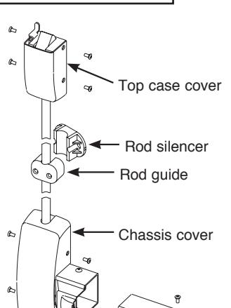
End cap
- 1. Confirm operation of exit device. Adjust rods as needed.
- 2. Attach top and center chassis covers and end cap as shown and secure with #8-32 oval head screws.
- 3. Locate rod guide and rod silencer at center of rod. Rod must move freely in rod guide without rubbing.
- 4. For doors over 96": Install two (2) top rod guides equally spaced between the top case and chassis cover. Rod must move freely in guides.
Note: Additional information for prefixes: AL-, 55, 56, 57, & 58, see appropriate instructions:
AL- prefix - A7224
55- prefix - A6808
56- prefix - A6876
57- prefix - A6810
58- prefix - A6835
WHEN NECESSARY TO OBTAIN 1/8" GAP
(D) Adjusting tube
NOTE: SHIM TOP STRIKE
(M) Top rod
Note: Use two (2) No. 10 steel screws and mortise nuts (when provided) in the position illustrated in the top chase. Steel mortise nuts are twin knurled for identification.
(L) Rod adjustment pin
SIXTH INSTALLING THERMAL PIN FOR 12-NB8700
12-NB8700 fire rated devices require the installation of a thermal pin assembly to maintain Fire Listing. See Instruction Sheet A7436 for proper installation in wood and metal doors.