Motorized ELR Installation Instructions – I-ED01722-Rev04
Open the original PDF document
View PDF

DEVICES COVERED IN THIS DOCUMENT:
Motorized Electric Latch Retraction (MLR) for 4500 and 4600 Exit Devices
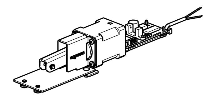
2-649-5007 Motorized Electric Latch Retraction Kit
A. Electrical Input Requirements:
Filtered and Regulated Power Supply
Voltage: 24VDC ±10%
Current: 1A MAX Inrush, 400mA MAX Holding
Non-polarized leads
PROVIDES SIMULTANEOUS ELECTRIC LATCH RETRACTION AND DOGGING (PUSH BAR DEPRESSED )
DO NOT REMOVE ANY REGULATORY LABELS ADHERED TO THE DEVICE.
A 4500 or 4600 Exit Device for a 36" door with an MLR can be cut down a maximum of 2" (Minimum door width-34"). A 4500 or 4600 Exit Device for a 48" door with an MLR can be cut down a maximum of 8" (Minimum door width-40").
| 2-Conductor Wire Run | |||
|---|---|---|---|
| Distance | Wire Gauge | ||
| 70' | 22 | ||
| 110' | 20 | ||
| 180' | 18 | ||
| 280' | 16 | ||
| 450' | 14 | ||
| 720' | 12 | ||
- B. Installation Instructions (For Kit only. For Motorized ELR already installed in exit device skip to section C)
- 1. Remove the Exit Device Head Cover by removing the four screws.
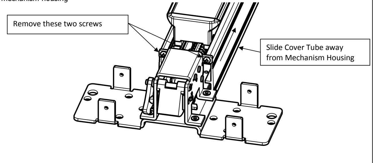
- 2. Separate the mechanism housing from the cover tube. Remove the two screws shown and slide the cover tube away from the mechanism housing

3. Remove the manual dogging assembly from the mechanism housing baseplate (if present) and discard.
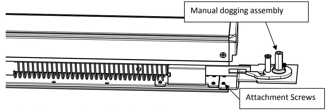
4. Attach the mounting plate of (2-649-5007) MLR kit to the Mechanism Housing Assembly Baseplate using the supplied screws through the holes that secured the manual dogging assembly.
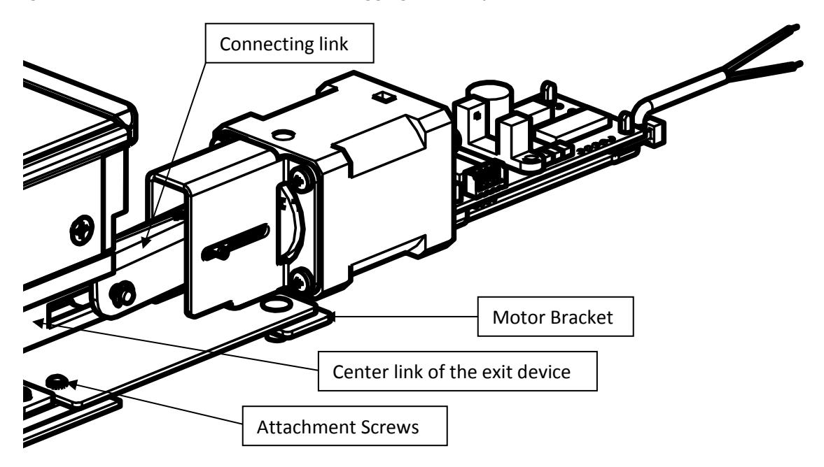
- 5. Attach the Connecting Link to the Center Link of the exit device using the supplied clevis pin and retaining rings.
- 6. Slide the Mechanism Housing back into the Cover Tube. Verify the flanges on the Motor Bracket slide into the same mounting grooves on the Cover Tube as the Mechanism Housing Assembly Baseplate.
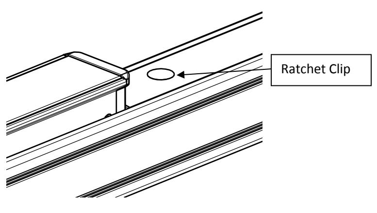
- 7. Install the Ratchet Clip into the dogging hole of the Cover Plate.

Motorized Electric Latch Retraction Adjustment
- 1. Verify the device is properly adjusted for mechanical operation. Electric operation should not exceed the mechanical operation or there will be a high risk of damage to the device. We suggest setting the latch retraction under electric operation at 1/16" less than the latch retraction under mechanical operation.
- 2. Locate the adjustment screw in the rear of the motor assembly. Rotate the adjustment screw clockwise to increase the latch retraction or counterclockwise to decrease the latch retraction.
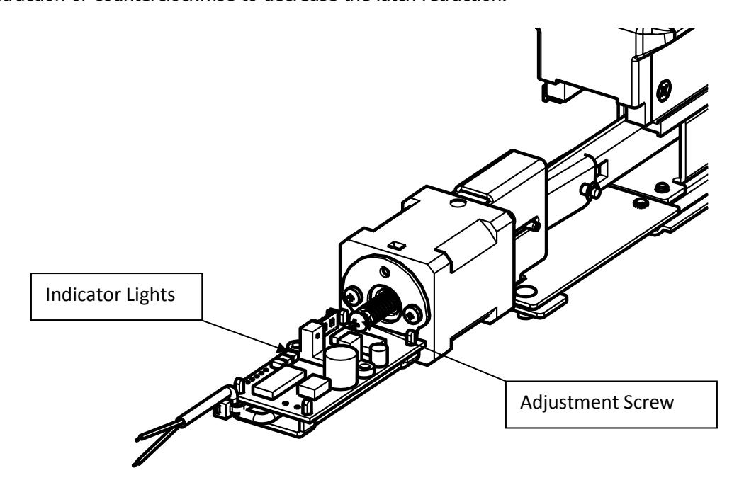

C. Onboard Indicator Light Assignments:
Maintain input power to the exit device and check the onboard indicator lights.
Remove input power before attempting a solution.
|
Green
(Power) |
Yellow
(Sensor) |
Red
(Error) |
Indication | Possible Solution |
|---|---|---|---|---|
| Off | Off | Off | No Power. |
Connect the wiring
between the power supply and the exit device |
| On | On | Off |
Normal Operation. The push bar is retracted to
the dogged position and dogged; The latch is retracted by default. The device is allowed 2 attempts |
|
| On | Off | On |
Error in operation. The push bar did not
retract to the dogged position within 2 attempts. |
Rotate the adjustment
screw counterclockwise to decrease the latch retraction. |
| On | On | On |
Error in operation. Without power being
removed, the push bar went from being dogged to unintentionally being extended and then the push bar did not retract to the dogged position within 2 attempts. |
Clear the jam condition
manually. |
| On | Blink | On |
Error in operation. The push bar did not
extend from the dogged position when the power was last removed. The device will not attempt a retraction |
Clear the jam condition
manually. |
| On | Simultaneous Blink |
Error in operation. The input voltage dropped
below the specification during operation. |
Decrease the wire run or
increase the wire gauge. |
|
| On | Alternating Blink |
Error in operation. An electronics fault was
detected. |
An electronics replacement
is required. |
|