Marks USA REX Cylindrical Electrified Leverset Installation Instructions
Open the original PDF document
View PDF

REX: Request To Exit Cylindrical Lockset Installation Instructions©
1
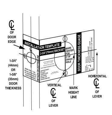
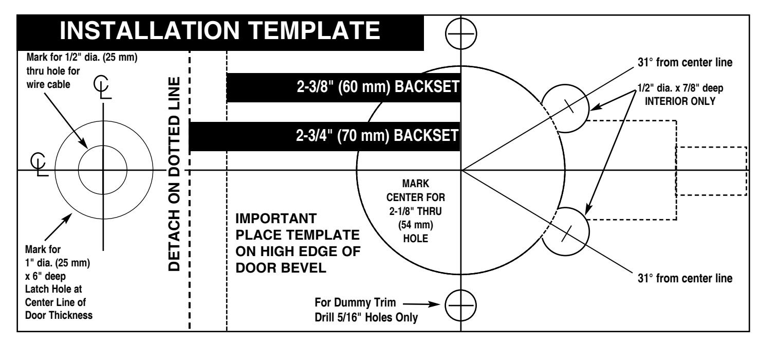
See template for measurements.
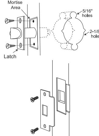
1. Affix paper template to door and follow template instructions in preparing door. Install latch and strike.
DOOR PREP: DOOR PREP (cont'd): 2
- 1. Locks are factory assembled with a spacer ring for 1-3/4" door thickness when lock chassis is firmly against ring.
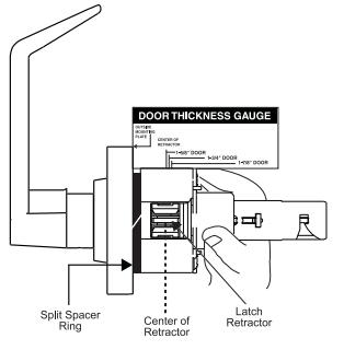
- 2. Locks can be adjusted for 1 5/8" to 1-7/8" door thickness. Before installation, use door thickness gauge on template as shown to check lock chassis position. Center of latch retractor should align with mark on gauge for appropriate door thickness.
DOOR PREP (cont'd): INSTALL LOCK: 2A 3
Adjusting for Other Door Thickness:
Remove outside lever. (See lever/cylinder installation section on pg.2)
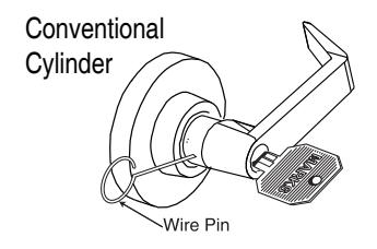
CONVENTIONAL CYLINDER:
- 1. Turn key in cylinder 45° in either direction.
- 2. Depress outside lever catch with wire pin through small hole in rose/lever and pull lever off tube.
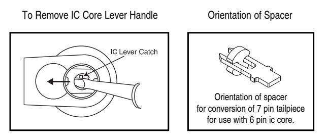
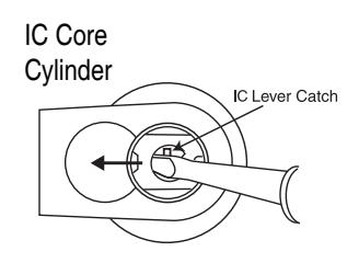
IC CORE CYLINDER:
- 1. With IC core removed, use screwdriver inside lever to depress lever latch.
- 2. Pull off lever. If retractor is not on center, screw chassis in or out to align with mark. If adjusting for doors thinner than 1-3/4" thickness, split spacer must be removed.
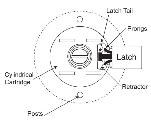
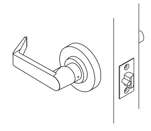
- 1. Push lock partially through 2-1/8" hole from the outside so that retractor engages latch tail.
- 2. Prongs must engage inside lock housing.
- 3. Align outside rose so rose posts enter thru-bolt holes in door.
- 4. Check from inside of door to see if latch is properly engaged.
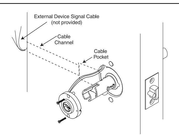
4 INTERIOR BACKPLATE ASSEMBLY:
-
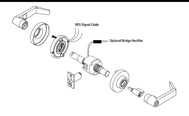
1. Connect the REX signal wires in the rose assembly to the External Device Signal Cable.
NOTE: There are 3 REX wires:
- Black is common
- Blue is normally closed
- Yellow is normally open
2. PUSH ALL CONNECTED WIRES INTO THE CABLE POCKET Option:
If electrically operated lock, connect the bridge rectifier to the power source (24v AC/DC). Place the connected bridge rectifier into the cable pocket.
INTERIOR BACKPLATE ASSEMBLY (cont'd): 4A 5 INSTALL INTERIOR LEVER:
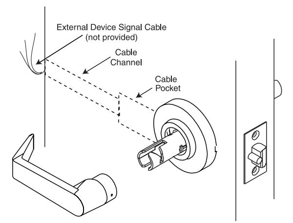
- 1. After all wire connections are made and placed in the cable pocket, push lock completely through the 2-1/8" hole making sure that the latch is properly engaged with lock chassis.
- 2. Push the inside rose to the door surface, aligning the thru-bolt holes with the outside rose.
- 3. Be sure not to pinch any of the wires.
- 4. Fasten with 2 thru-bolts.
- 5. Press rose cover over inside rose.
- 1. Press lever on lock tube, slightly wiggle and push until lever engages lever catch and connector prongs.
- 2. Test lever to be sure it is on securely.
- 3. Check lock for proper operation before closing door.
Lever / Cylinder Installation Section
TO REINSTALL OUTSIDE LEVER:
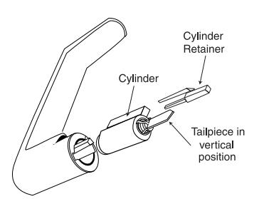
Conventional Cylinder:
- 1. Align lever catch of outside tube to face latch front.
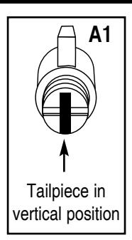
- 2. Tailpiece must be in a vertical position in cylinder. (Fig. A1)
- 3. Insert cylinder in lever.
- 4. Press cylinder retainer into lever until flush with base of lever.
- 5. Turn key in cylinder 45° in either direction.
- 6. Slide lever on tube until it stops at the lever catch.
- 7. Slightly wiggle and push until lever engages lever catch & connector.
- 8. Test lever to be sure it is on securely.
IC Core Cylinder: 1. To install IC core, push lever on door in horizontal position
- until secure.
- 2. Insert control key (marked with a "C") into IC core and turn clockwise.
- 3. Insert tailpiece into core.
- 4. With control key in core, insert core fully into lever.
- 5. Turn control key 15° counter-clockwise to lock cylinder in place. Remove control key.
REPLACING CYLINDERS
Conventional Cylinder Removal (all functions):
1. Remove key from cylinder and pull plastic cylinder retainer from lever, then remove cylinder.
Installation:
- 1. Tailpiece must be in vertical position in cylinder.
- 2. Insert cylinder in lever.
- 3. Press plastic cylinder retainer into lever until flush with base of lever.
NOTE: Use MARKS tailpieces only. Lock will NOT function with other tailpieces. Be sure tailpiece is in a vertical orientation.