Marks USA IQ7 Rim Exit Device Interface Installation Instructions
Open the original PDF document
View PDF

IQ7K Rim Exit Device Lockset Installation Instructions©
1
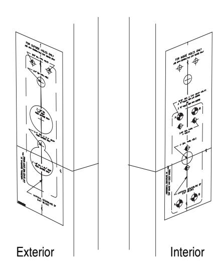
For existing Exit Device installation:
Remove the current exit device and set aside. Mark the vertical and horizontal lines of the inside spindle hole and outside lever hole. The marked lines are used to correctly position the drilling templates.
NOTE: Drilling template is supplied with adapter plate.
For New Installation:
Mark a vertical and horizontal line of the inside spindle hole and outside lever hole.
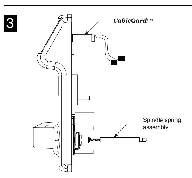
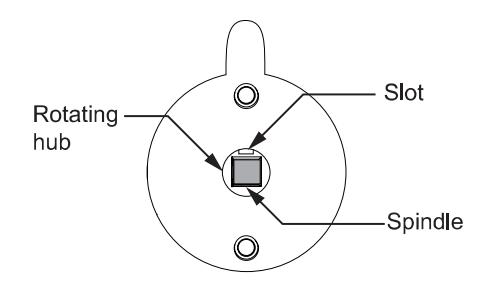
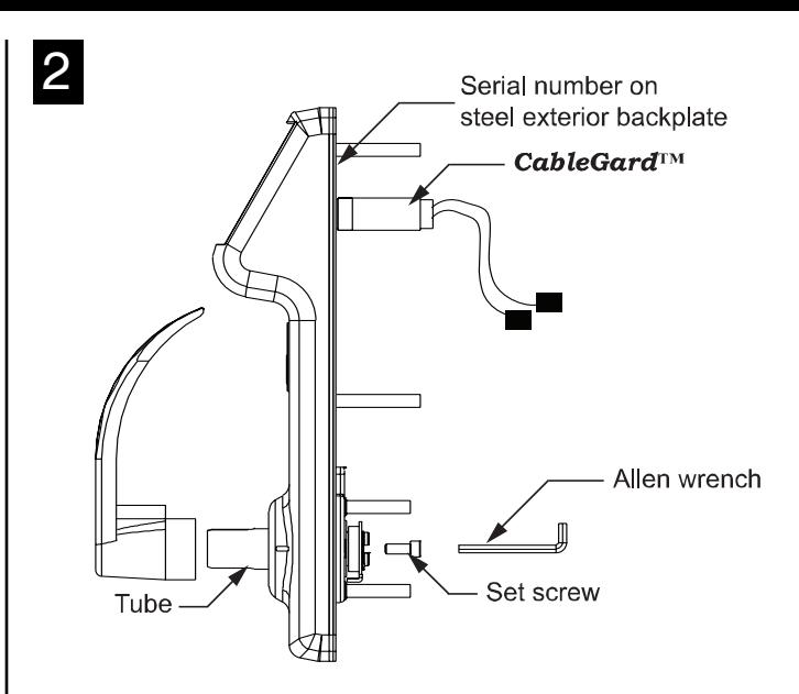
After the lever is assembled, insert spindle spring assembly into rotating hub. For alignment of spindle and hub, see below.
Install Lever:
- 1. Position lever on tube with correct handing, and fasten set screw using allen wrench as shown above.
- 2. i-Que is self adjusting for 1-3/4" 2" door thickness.
4
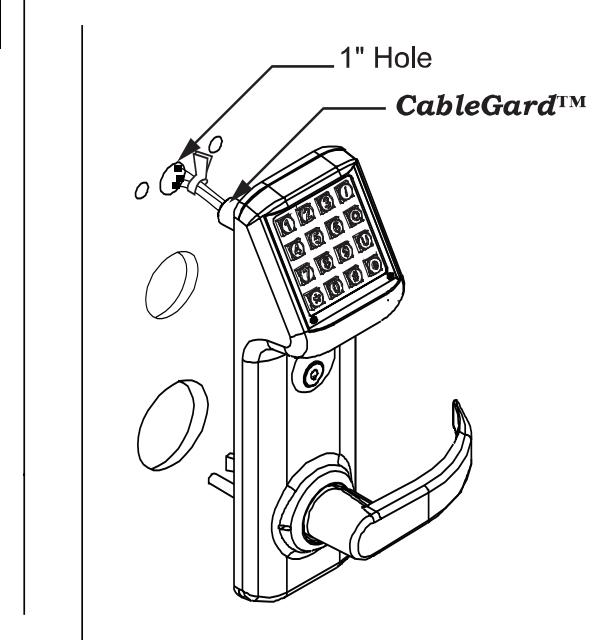
Pass the cable assembly with connectors through the 1" hole. Then place the outside trim assembly on the door.

IQ7K Rim Exit Device Lockset Installation Instructions©
5
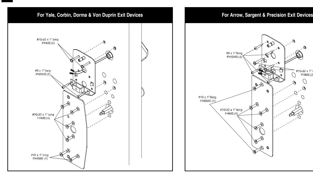
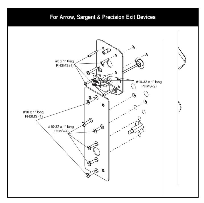
- 1. Install the Adapter plate: While holding the adapter plate in position, install and secure the four 10-32 x 1" flat head machine screws. ( NOTE: Ensure that the outside trim is still aligned in the vertical position at this point. )
- 2. Battery Backplate: Feed wires and connectors through the battery backplate. ( NOTE: See adapter plate instructions for the correct hole. ) While holding the battery backplate in place install the two 10-32 x 1" pan head screws.
- 3. Install the Battery Strap: Fasten with the two #8 x 1" pan head screws. ( NOTE: Do not install the battery pack until the assembly is complete. )
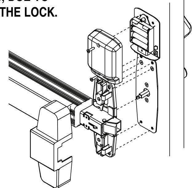
- 4. Exit Device Installation: Holding the exit device head in place, install the mounting screws. (For information on this step, please refer to the installation instructions supplied with the adapter plate.)
NOTE: USE ONLY ALKALINE BATTERIES, DUE TO PREDETERMINED POWER SETTINGS IN THE LOCK. 6
Note: All wire pairs are color coded to connect with like colored pairs.
- 1. Once the exit device is fully installed, install the battery pack. There are two sets of wires. The Yellow and Black wires are used for the reset function ( see programming guide ). The Red and Black (or Gray) wires will be connected to the battery pack.
- 2. Place the battery holder over the center grooved stud .
- 3. Install the battery cover with two finished 8-32 screws. Battery cover has a lip which engages battery backplate.
I-707 10.08 Page 2