Marks USA IQ2 Mortise Lockset Installation Instructions
Open the original PDF document
View PDFIQ2 - Mortise Lockset Installation Instructions©
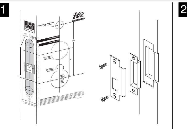
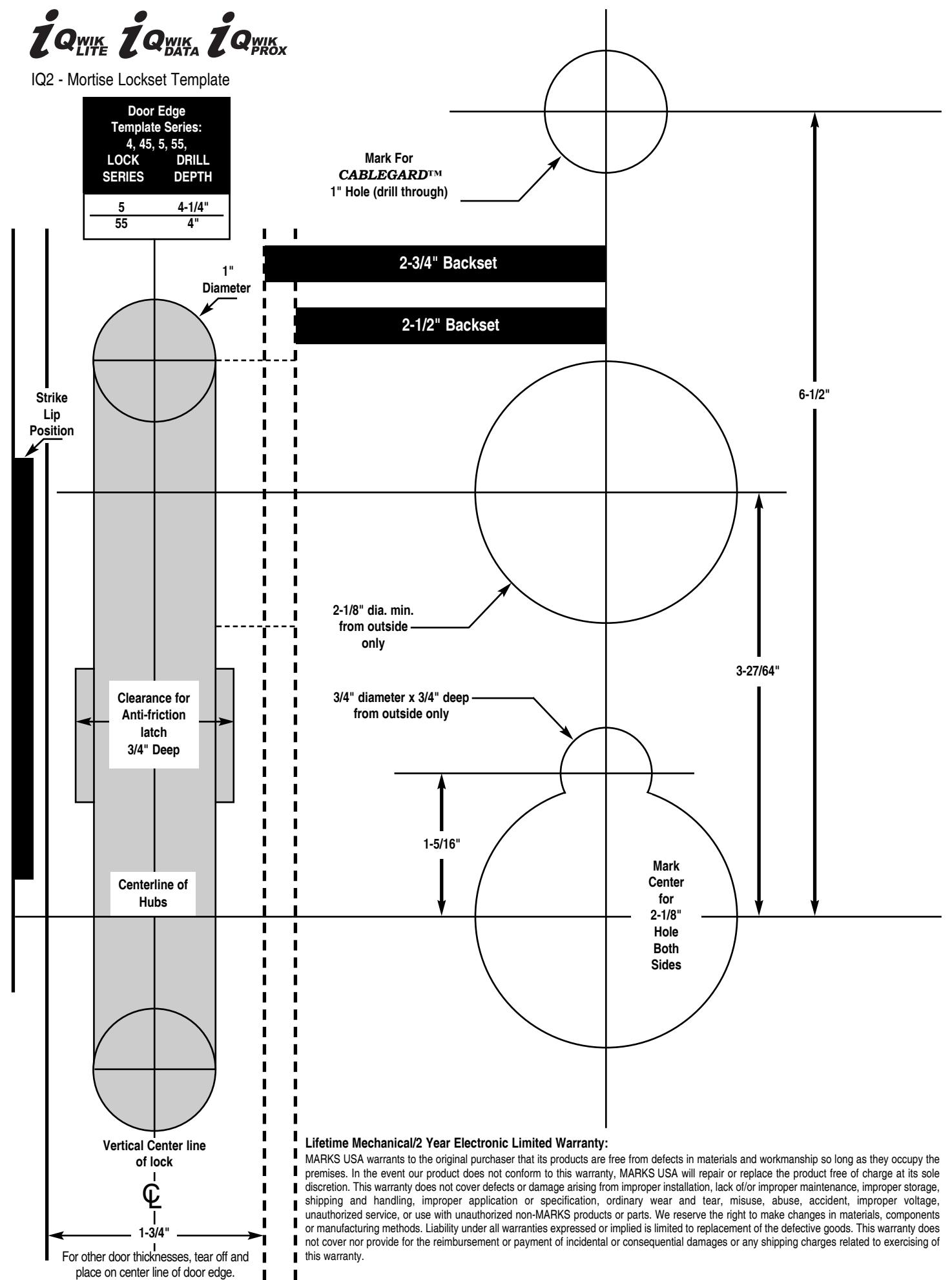
See template for measurements on page 4. See page 3 for instructions on installing the lock body.
Affix paper template to door and follow template instructions in preparing door. Install strike and dust box.
3
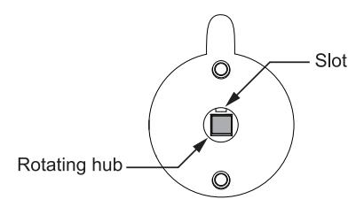
1. VERY IMPORTANT:
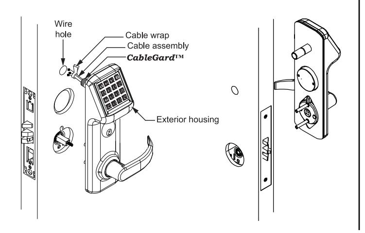
Align outside rotating hub in exterior housing so the slot is facing up. Insert spindle spring assembly into outside lock hub.
2. Pass the cable assembly with connectors through the wire hole ,then mount exterior housing through door preparation. Make sure the spindle engages with the rotating hub in the correct orientation.
Assemble Lever:
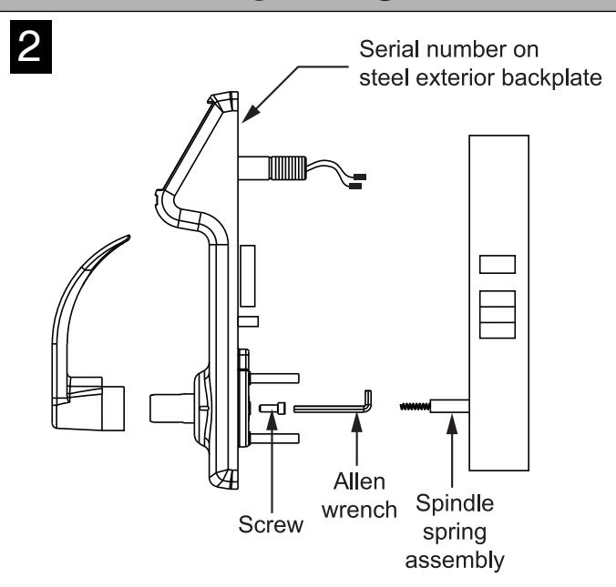
- 1. Assemble inside and outside levers on shafts for correct handing, using screw inside shaft to secure levers.
- 2. Locks are prepared for 1-3/4" door thickness. For other door thicknesses, see page 2. Locks are supplied with 1-1/8" cylinder. For other cylinder options, see page 2.
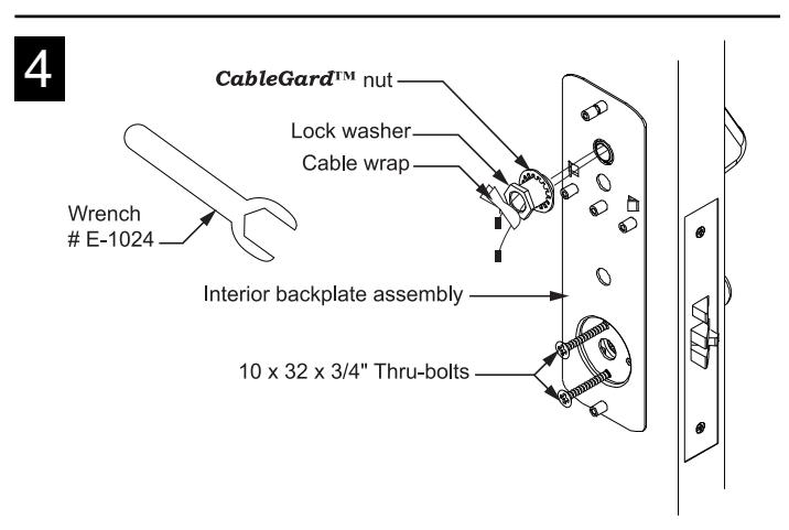
Remove packing screw from battery cover to access interior backplate.
- 1. Feed the cable assembly with connectors through the backplate, lock washer and CableGard™ nut.
- 2. While holding the interior backplate in position, loosely install the CableGard™ nut first, then the two screws through backplate and into posts.
- 3. Tighten the CableGard™ nut on the CableGard™ using wrench supplied. When the connection is firm, secure the thru-bolts.
- 4. Tear cable wrap and separate wires.
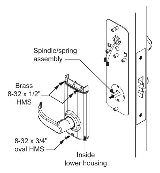
- 1. Assemble the inside lower housing on backplate, while engaging the spindle in lock hub. (Be sure wires are not pinched.)
- 2. Fasten with two brass #8 screws and the finished #8 screw at the bottom.
NOTE: USE ONLY ALKALINE BATTERIES, DUE TO PREDETERMINED POWER SETTINGS IN THE LOCK.
NOTE:
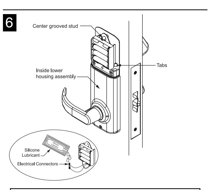
- • Dielectric Grease/Silicone lubricant is provided with each lockset by manufacturer. It is recommended to use during installation for all electrical connectors.
- • All wire pairs are color coded to connect with like pair.
- 1. Connect the red/black wires from the CableGard™ to the red/black wires from the battery pack. The two remaining pairs are only for the optional sensor- array package, as well as the "reset lock" function. (See programming manual.)
- 2. Place the battery holder over the center grooved stud .
- 3. When properly aligned, push down on the battery holder assembly, engaging the upper part of the hole into the groove of the stud. Battery holder will be held between tabs.

Note: PUSH ALL EXCESS WIRE LENGTHS DOWN THROUGH THE OPENING AT THE TOP OF THE INSIDE LOWER HOUSING.
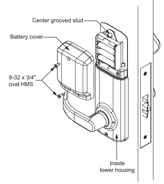
1. Attach the battery cover with two finished #8 screws. Battery cover has a lip which engages the lower inside housing, it is important that this lip be seated properly to insure correct alignment.
Options:
• Additional Door Thickness: For doors less than 1-3/4", use the E1038 spacers, one on each side.
• Additional Cylinder Options: For 1-1/4" cylinders, ring #E7006 must be used.

EK1038 Spacer Kit
Deadbolt Function
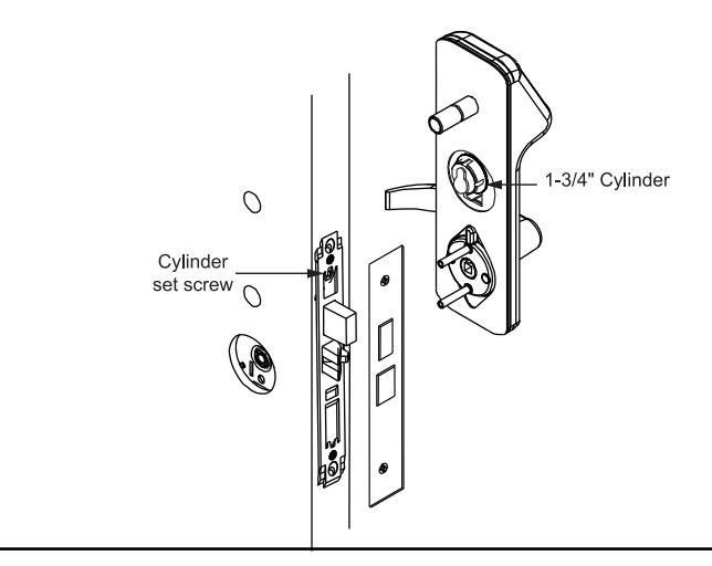
Deadbolt functions may use 1-1/8" cylinder integrated with trim or can use optional 1-3/4" cylinder directly engaged with mortise lock. With 1-3/4" cylinder screwed into mortise lock, tighten set screw then replace lock front.
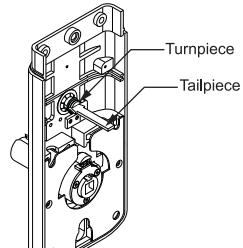
If Deadbolt Function, insert tailpiece into the lock's turnpiece-hub when assembling inside housing on door.
Lock Body Installation: Knob or Lever Mortise Locksets
PREPARING THE DOOR:
Note: If the strike already exists in the door frame, position lock using strike as reference. (See strike position on template.)
- 1. Draw horizontal line on both sides and edge of door at the desired height of knob above floor.
- 2. Draw vertical center line on door edge.
- 3. Draw vertical line on each side at the proper backset to align the templates.
- 4. Position template on edge and side of door. Mark holes ONLY for each side, top and bottom holes of mortise cavity on door edge.
- 5. Remove template; place lock face against door edge. Trace outline of faceplate as guide for faceplate routing.
MORTISE THE DOOR:
1. Mortise door for lock body and faceplate per instructions on template.
INSTALLING THE LOCK BODY:
- 1. Insert the lock into the cavity.
- 2. Mark & drill faceplate holes. Fasten with faceplate screws to hold lock in place.
INSTALLING THE STRIKE:
Select correct strike for handing.
- 1. Refer to template to determine strike location on jamb.
- 2. Using strike as template, mark and chisel recess. Drill screw holes and fasten.
LUBRICATION:
All locks come lubricated from the factory with a lithium based grease. We recommend, however, periodic lubrication of internal moving parts with a commercial quality grease. This can add years to the life of the lockset by reducing excessive wear. For more severe environments, lubrication should be applied more frequently.
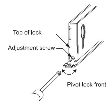
TO BEVEL SERIES 5, 55 LOCK:
- 1. Loosen adjustment screws at top and bottom of case.
- 2. Pivot front to desired bevel.
- 3. Re-tighten adjustment screws.
OUTSIDE OUTSIDE
LH Left Hand


RH
LHR Left Hand Reverse

RHR Right Hand Reverse
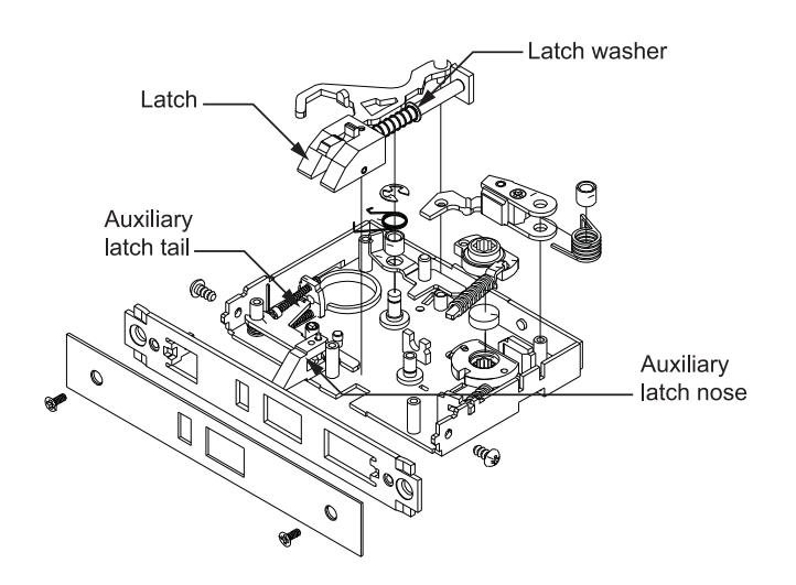
To Reverse Handing
- 1. Remove the 5 screws securing the lock body cover.
- 2. Remove the latch , turn it over, and re-insert it. Make sure the latch washer is in the position indicated, or the latch will not function properly.
- 3. Replace all parts and re-fasten the cover.
With Auxiliary Latch without Deadbolt
With Auxiliary Latch with Deadbolt
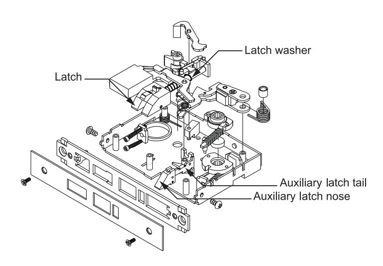
Assembly shown is for a right hand door
Page 4 I-202 03.09