Marks USA IQ1 Cylindrical Lockset Installation Instructions
Open the original PDF document
View PDF

IQ1 - Cylindrical Lockset Installation Instructions©
1 2
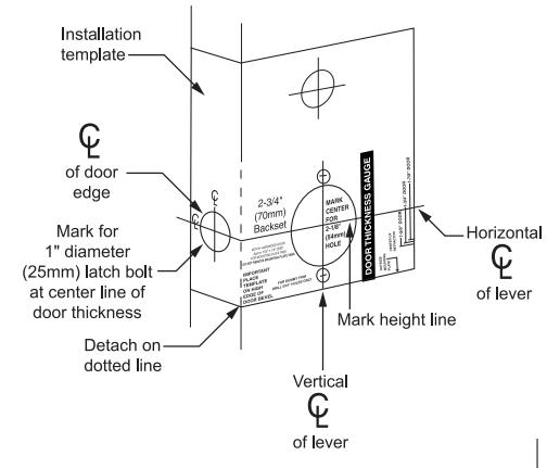
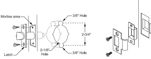
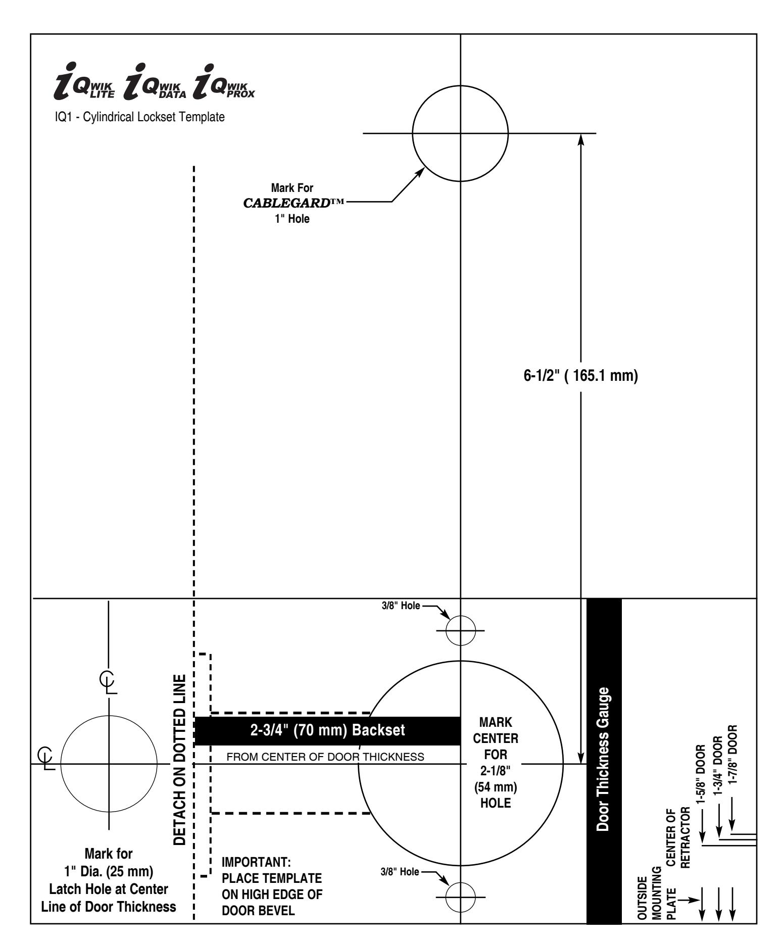
For measurements use template on page 4. Affix paper template to door and follow template instructions in preparing door. Install latch.
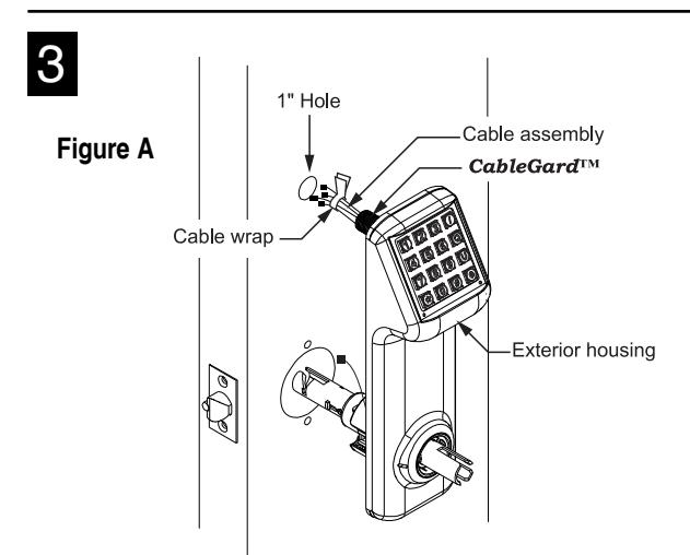
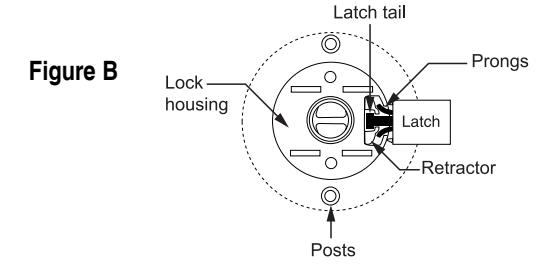
1. Pass the cable assembly with connectors through the 1" hole, then mount the exterior housing through door preparation. Make sure that the lock chassis and latch are properly engaged as shown in Figure B.
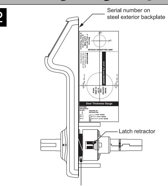
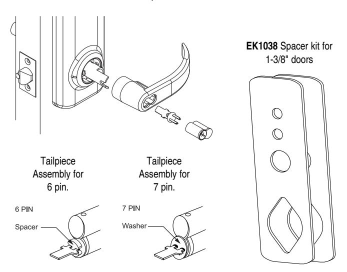
- 1. Locks are factory assembled with a ring for 1-3/4" door thickness, when lock chassis is firmly against ring. (For 1-3/8" doors, use the EK1038 spacers, one on each side.) When installing thinner than 1-3/4" door thickness, plastic ring must be removed.
- 2. Before installation, use door thickness gauge on template as shown to check lock chassis position. Center of latch retractor should align with mark on gauge for appropriate door thickness.
- 3. Make sure to adjust for correct door handing. To align retractor for desired handing, make sure the outside lever is not attached, and turn the chassis clockwise or counterclockwise until the retractor is in the desired position. Then attach outside lever.
- 4. Assemble outside lever on tube and check that lever engages lever catch before installation.
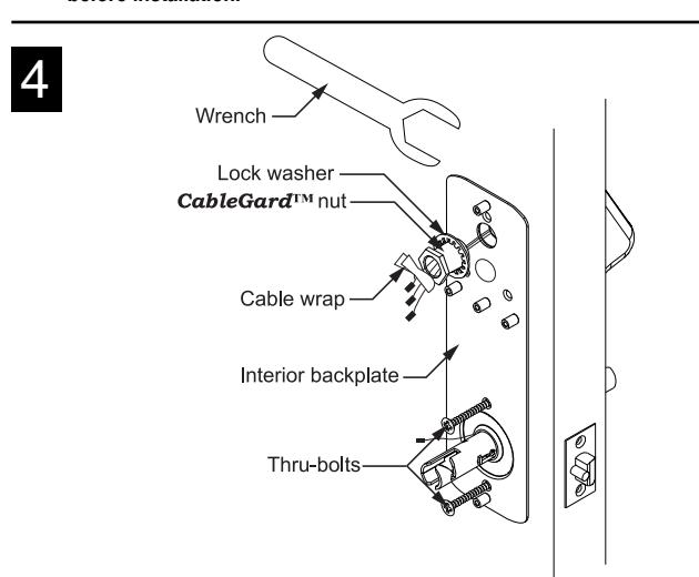
- 1. Remove screw from Battery Cover to access backplate.
- 2. Feed the cable assembly with connectors through the backplate, lock washer and CableGard™ nut.
- 3. While holding the interior backplate in position, loosely install the two thru-bolts.
- 4. Tighten the CableGard™ nut on the CableGard™ that passes through the door using supplied wrench. When this connection is tight secure the thru-bolts.
- 5. Tear cable wrap to separate wires.
NOTE: USE ONLY ALKALINE BATTERIES, DUE TO PREDETERMINED POWER SETTINGS IN THE LOCK.
NOTE:
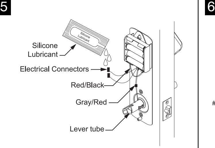
- • Dielectric Grease/Silicone lubricant is provided with each lockset by manufacturer. It is recommended to use during installation for all electrical connectors.
- • All wire pairs are color coded to connect with like pair.
- 1. Connect the grey/red wires from the CableGard™ to the grey/red wires from the lever tube. The two remaining pairs are only for the optional sensor-array package, as well as the "reset lock" function. (See programming manual.)
- 2. Connect the red/black wires from the CableGard™ to the red/black wires from the battery pack.
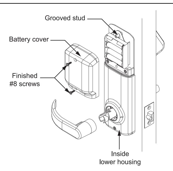
- 3. Place the battery holder over the center grooved stud .
- 4. When properly aligned, push down on the battery holder assembly, engaging the upper part of the hole into the groove of the center stud. This will connect the lower fork with the center post, giving a very secure fit.

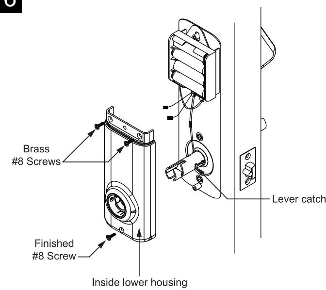
- 1. Slide the inside lower housing over the lever tube until it has passed over the lever catch. (Be sure wires are not pinched.)
- 2. Fasten with two brass #8 screws. Once secure, fasten the finished #8 screw at the bottom.
- 3. PUSH ALL EXCESS WIRE LENGTHS DOWN THROUGH THE OPENING AT THE TOP OF THE INSIDE LOWER HOUSING.
7
1. Attach the battery cover with two finished #8 screws. Battery cover has a lip which engages the lower inside housing, it is important that this lip be seated properly to insure correct alignment.
Inside Lever
1. Push lever on door in horizontal position until secure.
IC CORE CYLINDER
Installing IC Core:
- 1. Press lever on lock tube , slightly wiggle and push until lever engages lever catch and connector .
- 2. Test lever to be sure it is on securely.
- 3. Insert control key (marked with a "C") into IC core and turn clockwise.
- 4. Insert tailpiece with washer into core .
- 5. With control key in core, insert core fully into lever.
- 6. Turn control key approximately 15° counter-clockwise to lock cylinder in place. Remove control key.
- 7. Check cylinder and lock for proper operation before closing door.
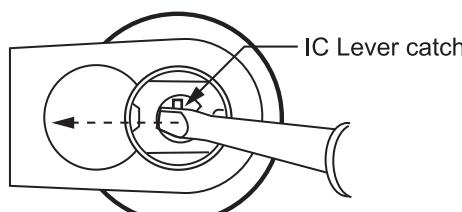
To Remove IC Core Lever Handle
| CYLINDRICAL IC CORES | ||||||
|---|---|---|---|---|---|---|
|
Kit for 6 & 7 pin Marks, KSP,
Best®, Falcon, Medeco® Keymark, Schlage® Small Format, 6 pin Sargent |
KR | HER1984 | ER | |||
| Kit for 6 & 7 pin Corbin | KRG | HER1984-G | ERG | |||
|
Kit for 6 & 7 pin Yale™
American Lever ONLY |
— | EAR1989-Y | EMY | |||
|
6 pin Schlage® Large Format
American Lever ONLY |
— | EF1903-F19 | CM | |||

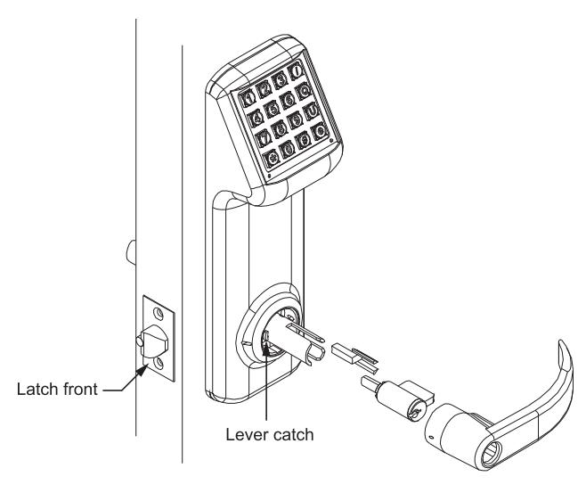
FIGURE B
INSTALLING THE LEVERS
Outside Lever
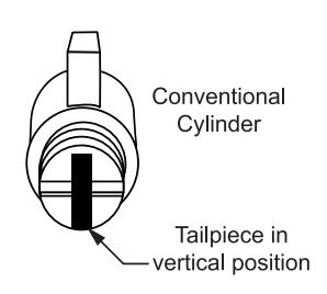
Installing Conventional Cylinder:
- 1. Align lever catch of outside tube to face latch front. (Figure A)
- 2. Tailpiece must be in a vertical position in cylinder . (Figure B)
- 3. Insert cylinder in lever.
- 4. Press cylinder retainer into lever until flush with base of lever.
- 5. Turn key in cylinder 45° in either direction.
- 6. Slide lever on tube until it stops at the lever catch .
- 7. Slightly wiggle and push until lever engages lever catch and connector .
| CYLINDRICAL TAILPIECES Cylindrical Conventional | ||||||
|---|---|---|---|---|---|---|
| FOR USE WITH | CODE | LEVER | CODE | |||
| Marks 1982 | K1 | E1903 | E1 | |||
|
Arrow PK 100C, ILCO 705,
Sargent 13-3266, Lori 1539, ASSA 65673, 65691, Abloy |
K2 | E1903-L | E2 | |||
|
Schlage® 23-001, Primus
Corbin-Russwin 2000-034 |
K3 | EF1903-C | E2 | |||
Lifetime Mechanical/2 Year Electronic Limited Warranty: MARKS USA warrants to the original purchaser that its products are free from defects in materials and workmanship so long as they occupy the premises. In the event our product does not conform to this warranty, MARKS USA will repair or replace the product free of charge at its sole discretion. This warranty does not cover defects or damage arising from improper installation, lack of/or improper maintenance, improper storage, shipping and handling, improper application or specification, ordinary wear and tear, misuse, abuse, accident, improper voltage, unauthorized service, or use with unauthorized non-MARKS products or parts. We reserve the right to make changes in materials, components or manufacturing methods. Liability under all warranties expressed or implied is limited to replacement of the defective goods. This warranty does not cover nor provide for the reimbursement or payment of incidental or consequential damages or any shipping charges related to exercising of this warranty.
MARKS USA • 365 Bayview Ave., Amityville, N.Y. 11701 631-225-5400 • 1-800-526-0233 • Fax: 631-225-6136 www.marksusa.com
I-101 03.09 Page 4