Marks USA I1 Mortise Lockset Installation Instructions
Open the original PDF document
View PDF
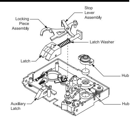
- 1. Remove the 5 screws securing the lock body cover.
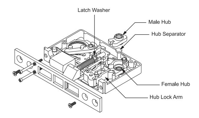
- 2. Remove latch , turn over and re-insert. (Note position of latch washer ).
- 3. Remove hub and hub spacer .
- 4. Unscrew and remove hub lever top .
- 5. Reverse position of long and short spacer .
- 6. Replace and re-fasten hub lever top .
- 7. Replace hub and hub spacer in reverse order.
- 8. Replace and re-fasten cover.
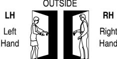
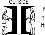
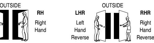
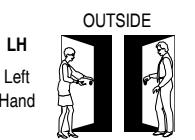
RHR Right Hand
Mortise Lockset Installation Instructions© To Reverse Handing Series 4 To Reverse Handing Series 5 with Auxiliary Latch (without Deadbolt)
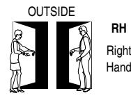
RH Right Hand
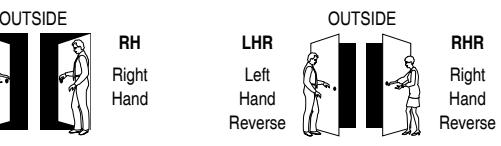
- 1. Remove the 5 screws securing the lock body cover.
- 2. Remove locking piece assembly and lever stop cylinder assembly .
- 3. Remove the latch , turn it over, and re-insert it. Make sure the latch washer is in the position indicated, or the latch will not function properly
- 4. Remove the top and bottom hubs as a single unit, flip them over and re-insert them so that the top hub is now on the bottom, and the bottom is now on top.
- 5. Replace and re-fasten the cover.
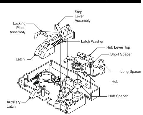
- 1. Remove the 5 screws securing the lock body cover.
- 2. Remove latch , turn over and re-insert. (Note position of latch washer )
- 3. Remove hub and hub spacer .
- 4. Unscrew and remove hub lever top .
- 5. Reverse position of long and short spacer .
- 6. Replace and re-fasten hub lever top .
- 7. Replace hub and hub spacer in reverse order.
- 8. Replace and re-fasten cover.
To Reverse Handing Series 4 with Auxiliary Latch
To Reverse Handing Series 5
- 1. Remove the 5 screws securing the lock body cover.
- 2. Remove the latch , turn it over, and re-insert it. (Note position of latch washer ).
- 3. Remove and replace hubs in reverse order. If lock has a lever support spring remove link from hub and replace in lower hub hole as before.
- 4. Replace and re-fasten the cover.
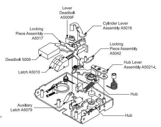
To Reverse Handing Series 5 with Auxiliary Latch (with Deadbolt)
- 1. Remove the 5 screws securing the lock body cover.
- 2. Remove cylinder lever assembly (A5016) and locking piece assembly (A5017 - for FD function only) .
- 3. Remove the latch , turn it over, and re-insert it. Make sure the latch washer is in the position indicated, or the latch will not function properly
- 4. Remove the top and bottom hubs as a single unit, flip them over and re-insert them so that the top hub is now on the bottom, and the bottom is now on top.
- 5. Replace and re-fasten the cover.
365 Bayview Ave., Amityville, NY 11701 631-225-5400 • 1-800-526-0233 • Fax 631-225-6136 • www.marksusa.com
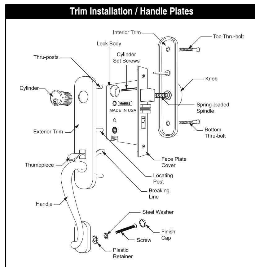
- 1. Place center thru-post of exterior trim through lock. NOTE: If thumbpiece is too long, shorten it at breaking line with pliers. Screw in cylinder to keep trim in place.
- 2. Position interior trim on door so turnpiece and spring-loaded spindle engage lock.
- 3. Insert top and bottom thru-bolts.
- 4. Insert and fasten bottom screw into bottom of the handle . Be sure plastic retainer and steel washer are placed under the head of bolt . After tightening, snap on finish cap.
- 5. When tightening cylinder set screws, be sure to use a No. 1 Screwdriver Bit ONLY.
IMPORTANT:
- 1. BE SURE SPINDLE ENGAGES HUBS.
- 2. Test lock operation with turnpiece, knob (or lever), thumbpiece and key.
- 3. Tighten all screws, including cylinder set screws.
I1 04.2009
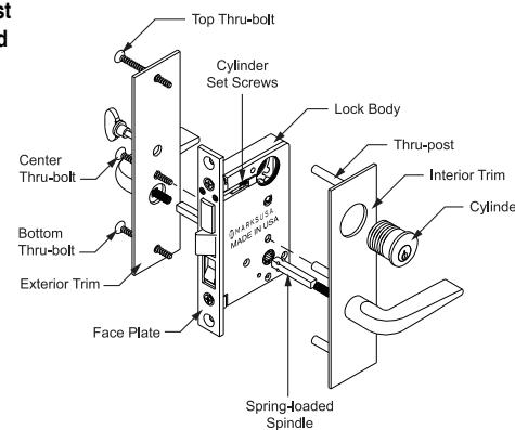
- 1. Place exterior trim with center thru-post through lock and engage spring-loaded spindle in hub .
- 2. When tightening cylinder set screws be sure to use a No. 1 Screwdriver Bit ONLY.
- 3. Screw in cylinder to keep trim in place.
- 4. Position interior plate with turnpiece and spring-loaded spindle to engage lock.
- 5. First insert center thru-bolt (if applicable) through interior trim into center thru-post. Then insert top and bottom thru-bolts .
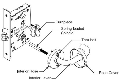
Trim Installation Lever Rose
- 1. Place interior and exterior lever with thru-posts and spring-loaded spindle through lock.
- 2. Attach assembly using 2 thru-bolts .
- 3. Slide rose cover over lever, align notch of cover with rose and snap on.
- 4. When tightening cylinder set screws be sure to use a No. 1 Screwdriver Bit ONLY.
- 5. Screw in cylinder(s) through collar(s) and tighten cylinder set screw(s) .
- 6. Insert turn piece and fasten with two screws.
Trim Installation Knob Rose
- 1. Place exterior knob with thru-posts and spring-loaded spindle through lock.
- 2. Attach roses with 2 thru-bolts and tighten. Snap on rose cover .
- 3. Insert knob with spring-loaded spindle through inside rose into hub . Screw threaded bushing of knob into rose. Tighten with spanner wrench supplied.
- 4. When tightening cylinder set screws be sure to use a No. 1 Screwdriver Bit ONLY.
- 5. Screw in cylinder(s) through collar(s) and tighten cylinder set screw(s) .
- 6. Insert turn piece and fasten with two screws.
IMPORTANT:
- 1. BE SURE SPINDLES ENGAGE HUBS.
- 2. Test for proper lock operation with turnpiece, knob (or lever), and key.
- 3. Tighten all screws, including cylinder set screws.
- 4. Attach faceplate cover, if applicable.
PREPARING THE DOOR:
Note: If the strike already exists in the door frame, position lock using strike as reference. (See strike position on template)
- 1. Draw horizontal line on both sides and edge of door at the desired height of knob above floor.
- 2. Draw vertical center line on door edge.
- 3. Draw vertical line on each side at the proper backset to align the templates.
- 4. Position templates on edge and sides of door. Mark holes ONLY for each side, and top and bottom holes of mortise cavity on door edge.
- 5. If lock has anti-friction latch, mark proper recess area on door edge template. (See lock body to determine proper side.)
- 6. Remove template; place lock face against door edge. Trace outline of faceplate as guide for faceplate routing.
MORTISE THE DOOR:
1. Mortise door for lock body and faceplate per instructions on template.
INSTALLING THE LOCK BODY:
- 1. Insert the lock into the cavity.
- 2. Mark & drill faceplate holes. Fasten with faceplate screws to hold lock in place.
- 3. Unscrew cylinder set screw enough to allow the cylinder to thread into the lock.
INSTALLING THE STRIKE:
- 1. Refer to template to determine strike location on jamb.
- 2. Using strike as template, mark and chisel recess. Drill screw holes and fasten.
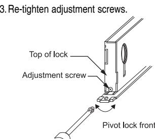
TO BEVEL SERIES 4, 4.5, 5, 5.5 LOCK:
- 1.Loosen adjustment screws at top and bottom of case.
- 2.Turn front to desired bevel.
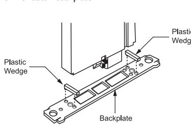
TO BEVEL SERIES 6, 7, 8 & 9 LOCK:
- 1. Remove lock backplate (2 screws).
- 2. Insert bevel wedges, top and bottom, under backplate.
- 3. Re-fasten backplate.
LUBRICATION:
All locks come lubricated from the factory with a lithium based grease. We recommend, however, continued periodic lubrication of internal moving parts with a commercial quality grease. This can add years to the life of the lockset by reducing excessive wear. For more severe environments, lubrication should be applied more frequently.
Trim Installation Knob or Lever Plates Lock Installation Handle, Knob or Lever Mortise Locksets
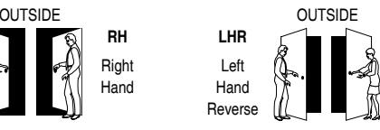
RHR Right Hand Reverse
To Reverse Handing Series 6 & 8
- 1. Remove lock body cover (3 screws).
- 2. Remove latch, turn over and re-insert. Note position of latch washer.
- 3. Replace cover and re-fasten.
LH Left Hand
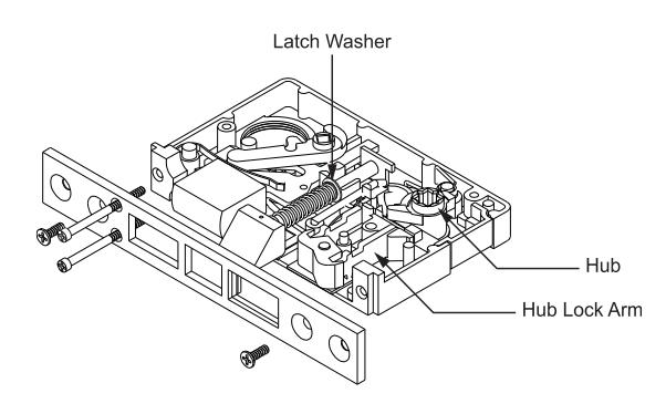
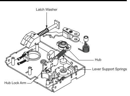
To Reverse Handing Series 7 & 9
- 1. Remove lock body cover (3 screws).
- 2. Remove latch, turn over and re-insert. Note position of latch washer.
- 3. Remove hub lock arm, turn over and re-insert.
- 4. Replace cover and re-fasten.