Marks USA I-5SR.AR Auto Reverse Mortise Instructions
Open the original PDF document
View PDF

5 Series "Auto-Reversing" Mortise Lockset Installation Instructions©
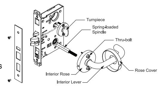
Trim Installation: Knob or Lever Plates
- 1. Remove faceplate from lock.
- 2. Position exterior plate assembly, making sure the spring-loaded spindle engages with lock.
- 3. Place rings/spacers over cylinder and screw into lock body, making sure the key slot is aligned vertically toward the lever.
- 4. Tighten cylinder set screw using a No. 1 screwdriver bit ONLY.
- 5. Replace faceplate on top of backplate and secure with two screws.
- 6. Position interior plate assembly with turnpiece and spring-loaded spindle, making sure the spindle engages with lock.
- 7. Insert and tighten mounting screws securely.
- 8. Check lock for proper operation before closing door.
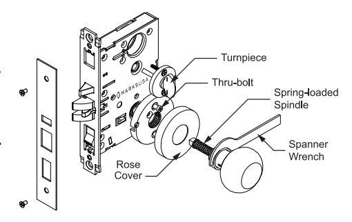
Trim Installation: Lever Rose
- 1. Remove faceplate from lock.
- 2. Position exterior and interior rose assemblies, making sure the spring-loaded spindle engages with lock from both sides.
- 3. Insert and tighten mounting screws securely from inside.
- 4. Slide rose cover lever, making sure to align notches on cover with slots in rose (horizontally) and snap on.
- 5. Position turnpiece assembly and secure with screws.
- 6. Place rings/spacers over cylinder and screw into lock body, making sure the key slot is aligned vertically toward the lever.
- 7. Replace faceplate on top of backplate and secure with two screws.
- 8. Check lock for proper operation before closing door.
Trim Installation: Knob Rose
- 1. Remove faceplate from lock.
- 2. Position exterior thru-bolted assembly and spring-loaded spindle, making sure the spindle engages with lock.
- 3. Place and secure inside rose with mounting screws.
- 4. Position rose shell and align notches on cover with slots in rose (horizontally) and snap on.
- 5. Insert knob with spring-loaded spindle through inside rose, making sure the spindle is engaged with lock.
- 6. Screw the threaded bushing into rose and tighten securely with spanner wrench (supplied).
- 7. Position turnpiece assembly and secure with screws.
- 8. Place rings/spacers over cylinder and screw into lock body, making sure the key slot is aligned vertically toward the lever.
- 9. Replace faceplate on top of backplate and secure with two screws.
- 10. Check lock for proper operation before closing door.

5 Series "Auto-Reversing" Mortise Lockset Installation Instructions©
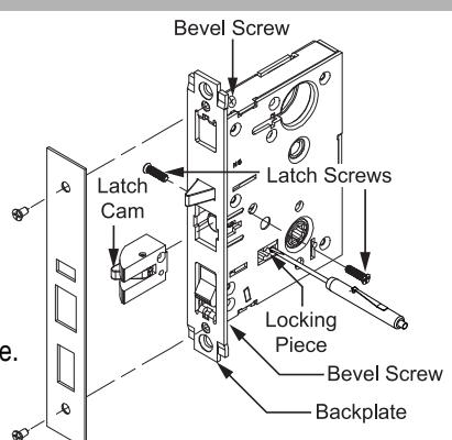
- 1. Remove front plate.
- 2. Depress latch, unscrew both latch screws (one from each side of the lock).
- 3. Tilt latch cam to remove latch. Re-insert for desired handing.
- 4. Replace the latch screws and adjust bevel of backplate.
- 5. Replace front plate.
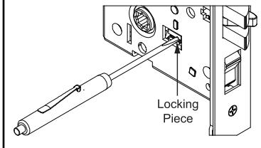
- 1. Push locking piece toward desired locked side.
- 2. Check for proper operation before installation.
REVERSE LATCH HANDING THE HUBS HANDING EXAMPLES
RH Right Hand
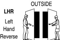
RHR Right Hand Reverse
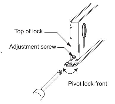
TO BEVEL LOCK LUBRICATION
- 1. Loosen adjustment screws at top and bottom of case.
- 2. Turn front to desired bevel.
- 3. Re-tighten adjustment screws.
All locks come lubricated from the factory with a lithium based grease. We recommend, however, continued periodic lubrication of internal moving parts with a commercial quality grease. This can add years to the life of the lockset by reducing excessive wear. For more severe environments, lubrication should be applied more frequently.
- 1. Push locking piece toward desired locked side.
- 2. Check for proper operation before installation.
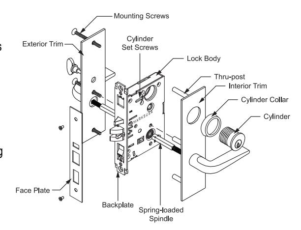
Trim Installation: Handle, Knob or Lever Mortise Locksets
PREPARING THE DOOR:
Note: If the strike already exists in the door frame, position lock using strike as reference. (See strike position on template)
- 1. Draw horizontal line on both sides and edge of door at the desired height of knob above floor.
- 2. Draw vertical center line on door edge.
- 3. Draw vertical line on each side at the proper backset to align the templates.
- 4. Position templates on edge and sides of door. Mark holes ONLY for each side, and top and bottom holes of mortise cavity on door edge.
- 5. If lock has anti-friction latch, mark proper recess area on door edge template. (See lock body to determine proper side.)
- 6. Remove template; place lock face against door edge. Trace outline of faceplate as guide for faceplate routing.
MORTISE THE DOOR:
1. Mortise door for lock body and faceplate per instructions on template.
INSTALLING THE LOCK BODY:
- 1. Insert the lock into the cavity.
- 2. Mark & drill faceplate holes. Fasten with faceplate screws to hold lock in place.
- 3. Unscrew cylinder set screw enough to allow the cylinder to thread into the lock.
INSTALLING THE STRIKE:
- 1. Refer to template to determine strike location on jamb.
- 2. Using strike as template, mark and chisel recess. Drill screw holes and fasten.