Marks USA I-3800 Gate Lock Instructions
Open the original PDF document
View PDFGate Lock Parts
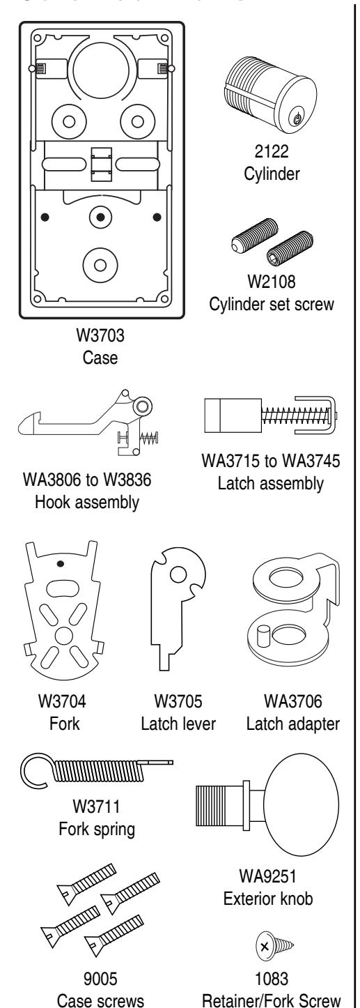
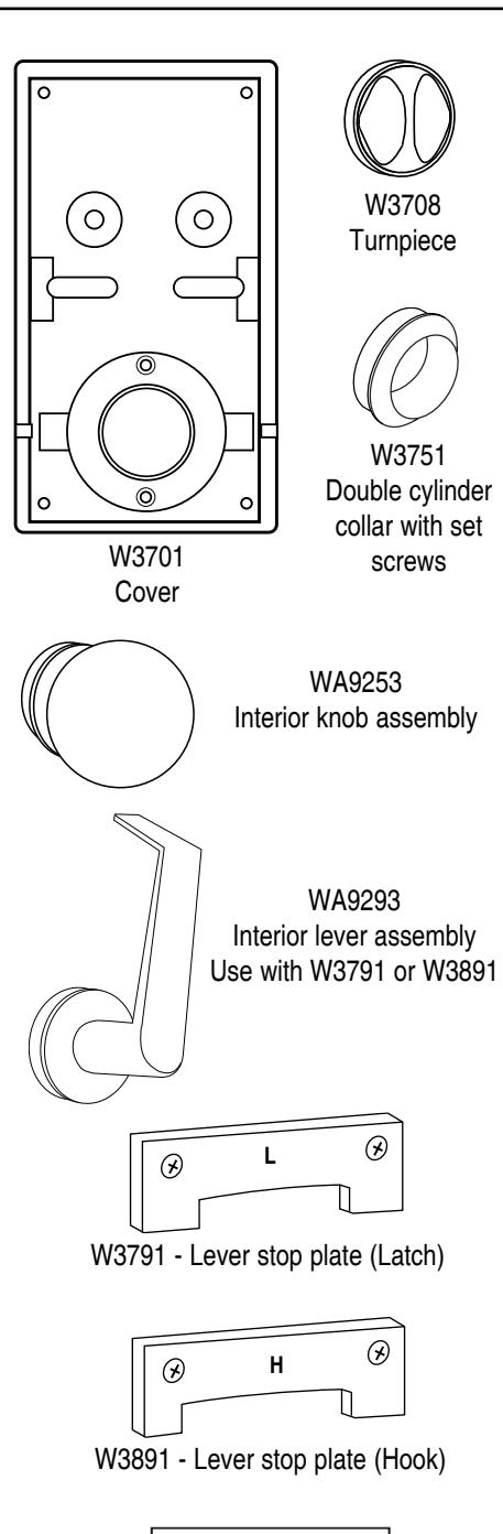
W3892 - Lever slide cover

365 Bayview Ave., Amityville, NY 11701 631-225-5400 • 1-800-526-0233 • Fax 631-225-6136 • www.marksusa.com
Reversible Gate Lock Installation Instructions©
US PATENT #4,875,725 "NO FALL OUT" FEATURE. Parts will not fall out when cover is removed. Replaces Multilock Gate Locks.
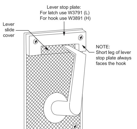
To Install Interior Lever:
- 1. Place spring over post and engage fork as shown in "how to assemble" section on page 3.
- 2. Attach lever assembly in cover and fasten with two screws.
- 3. Assemble case in lock frame and attach interior lever-cover assembly.
- 4. Attach plastic lever slide cover and lever stop plate with top two screws. Use plate marked "L" for latches or plate marked "H" for hooks.
How to Install Single & Double Cylinder Models
How To Install:
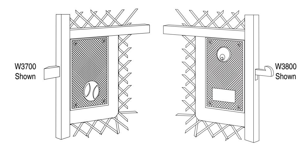
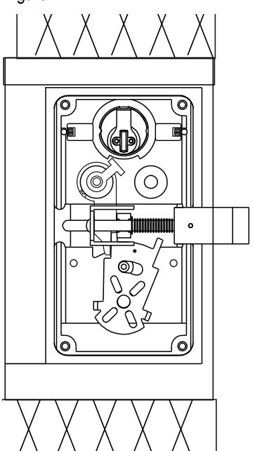
Insert assembled case from outside into lock frame of gate (see figure 1).
Single Cylinder Models:
- 1. From inside, place cover over case.
- 2. Engage thumbpiece tabs with slots in fork (see figure 2).
- 3. Test thumb turn operation. Insert and tighten case screws.
Double Cylinder Models:
- 1. Screw cylinder completely into double cylinder collar and tighten cylinder set screws from both sides.
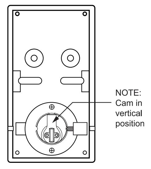
- 2. Install cylinder collar assembly in cover and fasten with two screws. Cam should be in vertical position (see figure 3).
- 3. From inside, place cover over case. Tighten case screws.
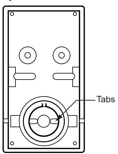
Figure 2 Figure 3
How to Assemble Hook & Latch Gate Locks
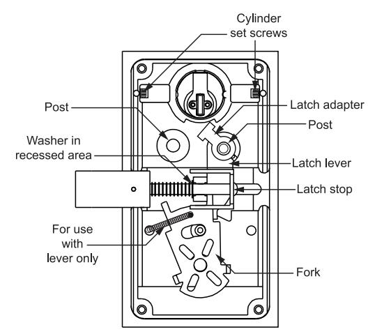
Figure 1 SPECIAL FEATURE If assembled properly, all parts will remain in position when lock is inverted.
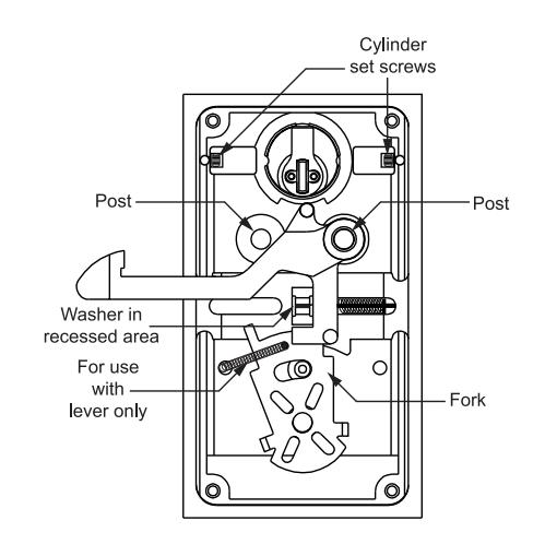
HOOK ASSEMBLY:
- 1. Insert cylinder completely into case. With cam in vertical position, tighten cylinder set screws from both sides.
- 2. While compressing spring on hook assembly, place over either post for left or right handing.
- 3. Washer fits in the recess of the cradle when the spring is released. Position the fork as shown so that it's movement retracts hook.
To Reverse:
Compress spring on hook assembly and lift out. Re-insert on opposite post.
LATCH ASSEMBLY:
- 1. Insert cylinder completely into case. With cam in vertical position, tighten cylinder set screws from both sides.
- 2. Engage latch lever with pin on latch adapter and place over either post.
NOTE:
Notched end of latch lever must be on outside leg of fork. Retract washer on latch rod to compress spring. Place latch assembly with washer in recessed pocket so end of latch stop overlaps edge of latch lever. Make sure latch nose faces desired direction for swinging door.
To Reverse:
Compress spring on latch assembly and lift out. Re-position latch lever and latch adapter on opposite post. Re-insert latch in opposite direction.