Major HIT-40MB3 Drill Guide for Mounting Brackets Instructions
Open the original PDF document
View PDF

1825 VIA BURTON ANAHEIM CA 92806
714-772-5202 / FAX 714-772-2302
EMAIL: MAIL@MAJORMFG.COM WEB: WWW.MAJORMFG.COM
INSTRUCTIONS FOR HIT-40MB3 DRILL GUIDE FOR LMB-03, 033 & 034 MOUNTING BRACKETS
WHEN USING POWER TOOLS ALWAYS WEAR EYE AND EAR PROTECTION!!

These are the most important tools that you will use in this installation.
Always use eye and ear protection!! Make sure all your tools are sharp and in good condition.
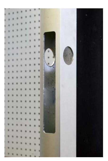
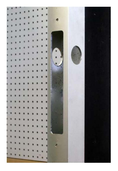
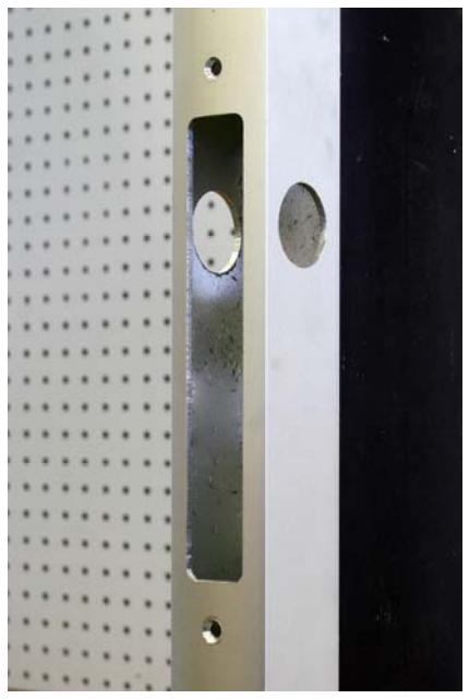
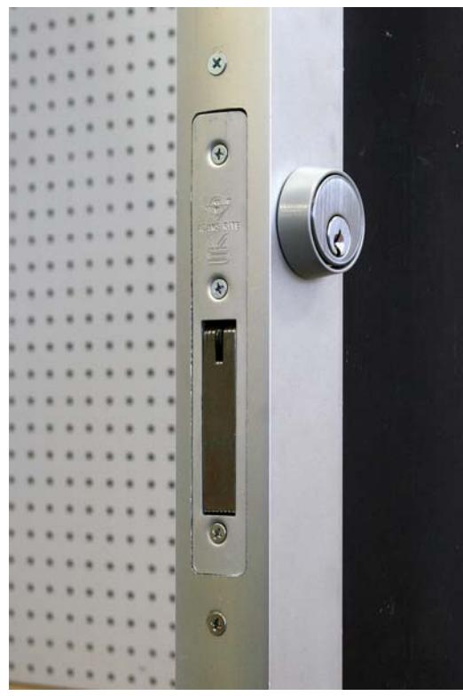
Here is a standard cut out for an aluminum door that will accept an Adams Rite style Lock. The cut out will be the same for a swing bolt, hook bolt or deadlatch. It will also be the same for a deeper style lock.
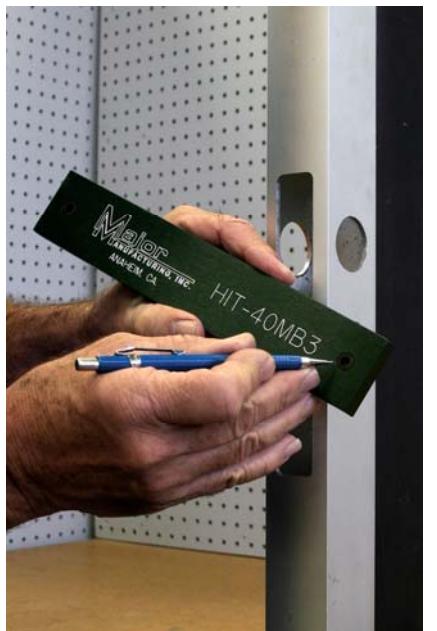
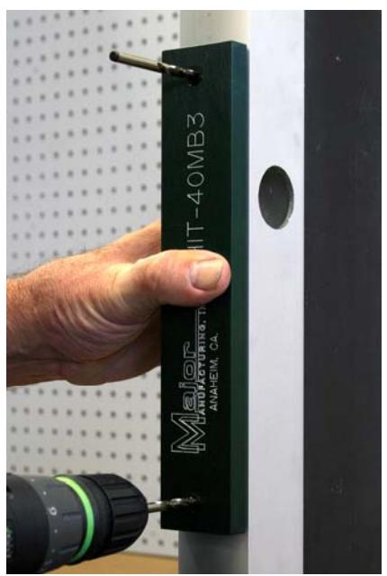
There are two hardened drill bushings installed in the drill guide, they are located at the top and bottom of the guide. Use a #7 drill bit when drilling.
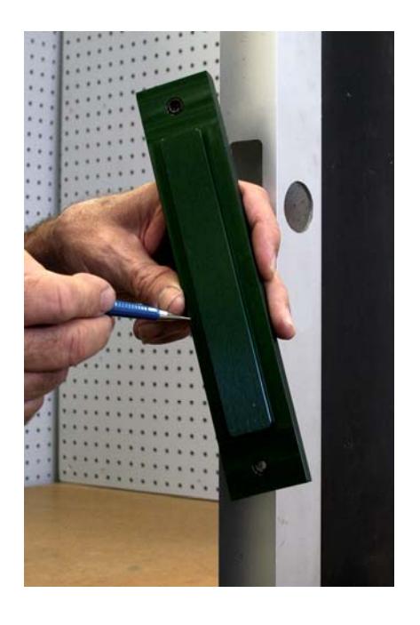
Here is the inside of the guide. There is a 1" x 6-7/8" area ( same size as the locks faceplate) that stands proud of the guide, this will drop into the cut out and locate the bracket holes.
Page 2 Copyright 2012—Major Manufacturing Inc
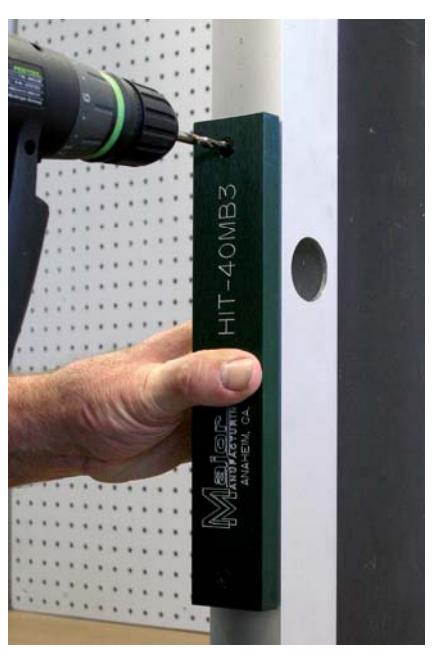
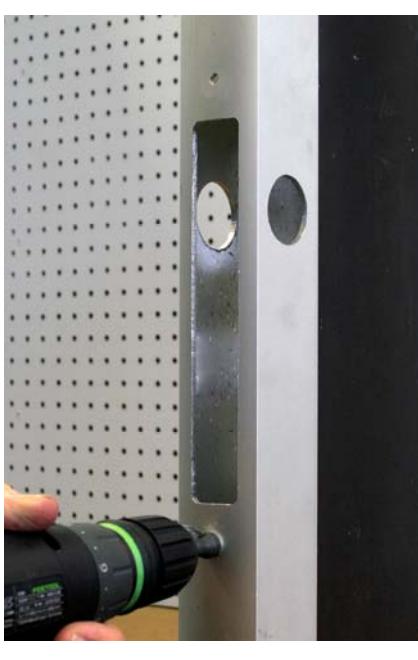
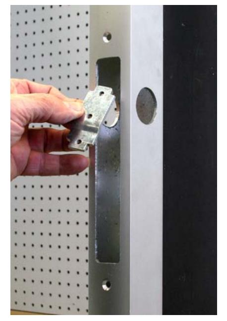
Drop into the cut out. If the lock was correctly installed there should be no top to bottom play. Drill one of the holes as shown.
If there was excessive play top to bottom, split the difference and then drill the first hole.
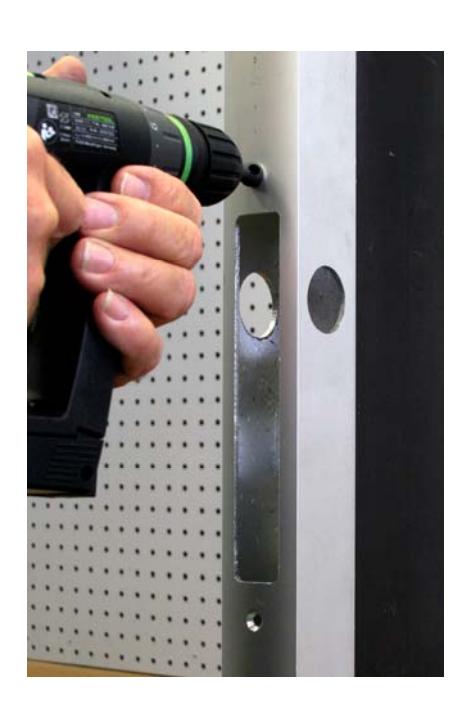
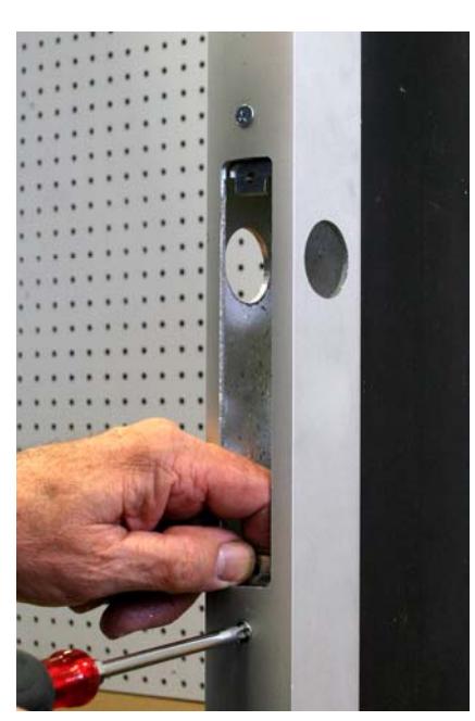
Drop a second drill bit into the hole that was just drilled, this will lock the guide in place and give the correct center to center spacing.
Drill the second hole.
Here is the opening with both #7 holes drilled.
Page 3 Copyright 2012—Major Manufacturing Inc
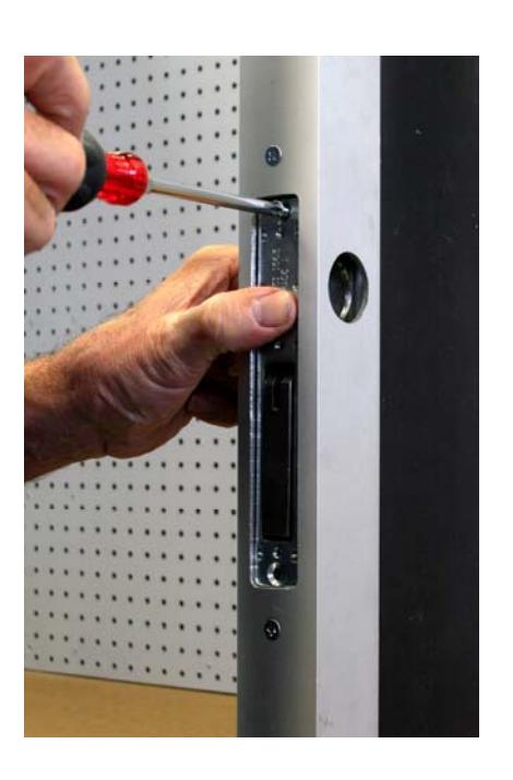
Counter sink both holes so the 10-32 machine screw is flush.
Holes are now counter sunk.
Use one of our mounting brackets that match the door style, LMB-03, LMB-033 or LMB-034. These will fit bevel or radius face doors.
Page 4 Copyright 2012—Major Manufacturing Inc
Install the bracket, do not tighten the screw all the way down at this time.
Install the second bracket, again do not tighten
Install the lock with the supplied 10-32 flat head screws. Once all of the screws have been centered, they can all be tightened down.
Install the cylinder and faceplate.
That's all there is to it!
Visit our web site at www.majormfg.com for more information or router recommendations, template guides and other templates to make your installations easier and faster. While there sign up for our newsletter and we will email new product information directly to you.