Major HIT-32-380 Template for Schlage AD 990 for Wood or Steel Doors Instructions
Open the original PDF document
View PDF

1825 VIA BURTON ANAHEIM CA 92806
714-772-5202 / FAX 714-772-2302 EMAIL: MAIL@MAJORMFG.COM
WEB: WWW.MAJORMFG.COM
INSTRUCTIONS FOR HIT-32-380 TEMPLATE FOR SCHLAGE AD 990 For WOOD OR STEEL DOORS
WHEN USING POWER TOOLS ALWAYS WEAR EYE AND EAR PROTECTION!!
Drill Bit Types
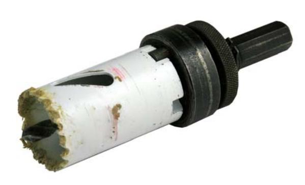
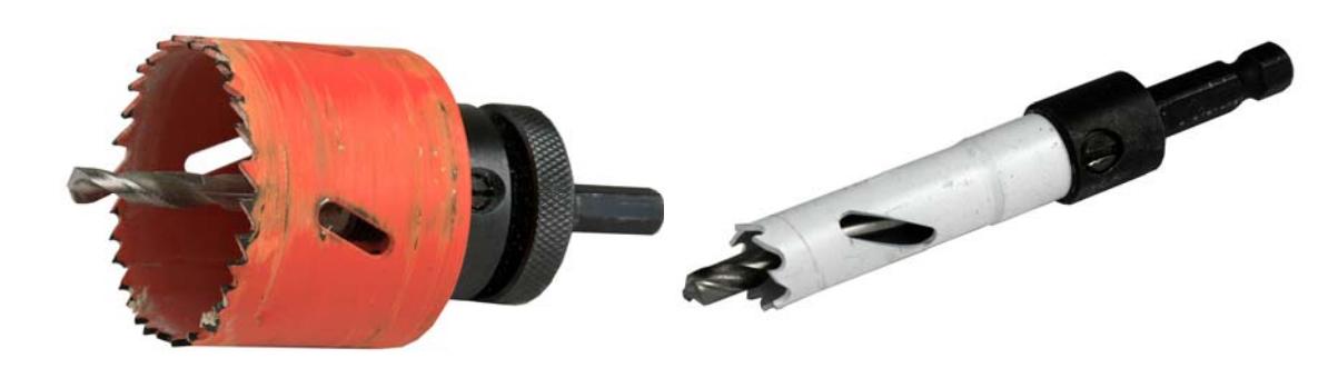
All hole saws are not created equal. A cheap hole saw from a home improvement center or one that has been dropped can be out of round and will not fit the drill bushings in our templates. Most hole saws are oversize due to the set in the teeth. A light pass arounb a belt sander or grinder will remove some of the set, the hole saw will still cut
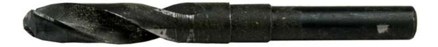
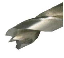
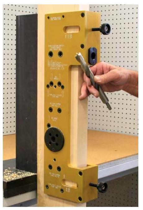
Shown above is a standard twist drill bit. They can be used on both wood or steel doors. Be sure to back out the bit when drilling to clear chips.
Shown above is a tri-flute drill bit. Do not attempt to use this in a drill guide. The lack of bearing surface will cause the bit to jam.

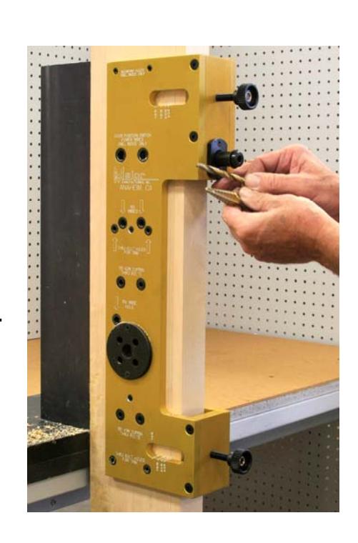
Shown above and at right is a brad point bit. They will produce a very clean hole in a wood door. Use at a low speed and back the bit out to clear chips. Do not use on a steel door.
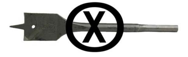
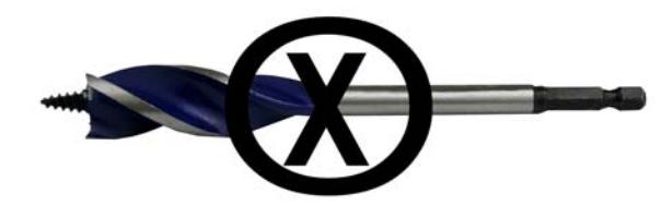
Shown above is a spade or paddle type bit. Do not attempt to use this in any drill guide. There is no bearing surface and you will jam the bit.
PAGE 1
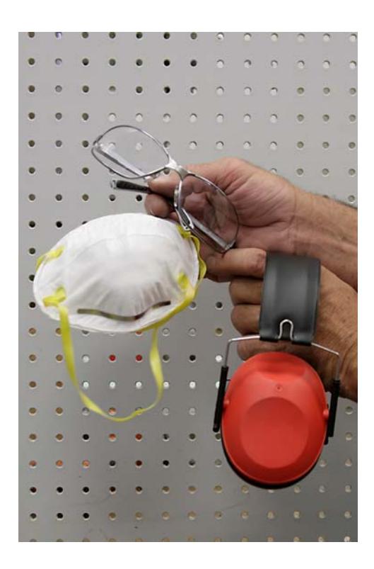
These are the most important tools that you will use in this installation.
Always use eye and ear protection when routing wood doors and jambs.
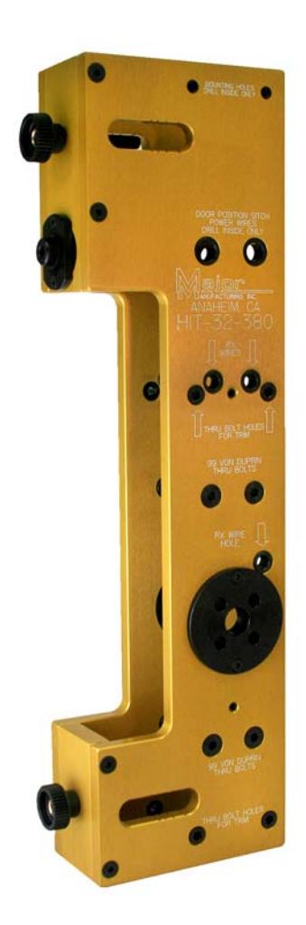
This template is reversible for both right and left hand doors. The outside holes for thru bolts will need to be enlarged after the drill guide has been removed from the door.
THE FOLLOWING DIRECTIONS ARE FOR A NEW INSTALLATION.
RETRO FIT DIRECTIONS WILL FOLLOW AFTER.
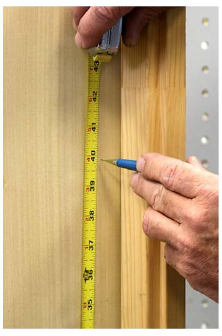
Locate the horizontal center line of the door and draw a locating line. This will be the center line of the device. According to Von Duprin this will be 39-13/16" to the finished floor . Install factory strike on the jamb side aligned on this center line.
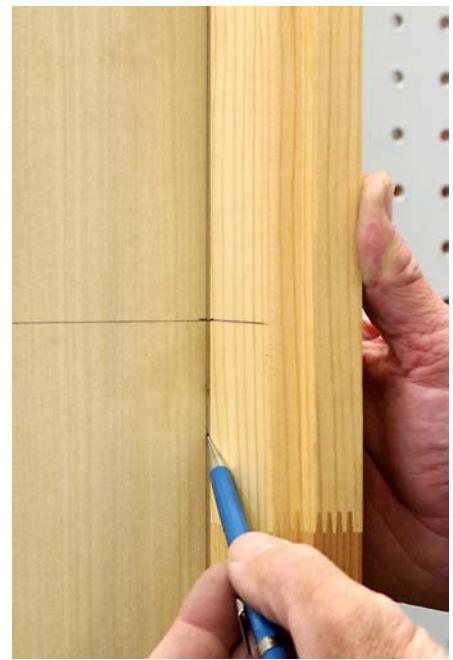
To determine the backset, draw a vertical line along the door stop onto the door.
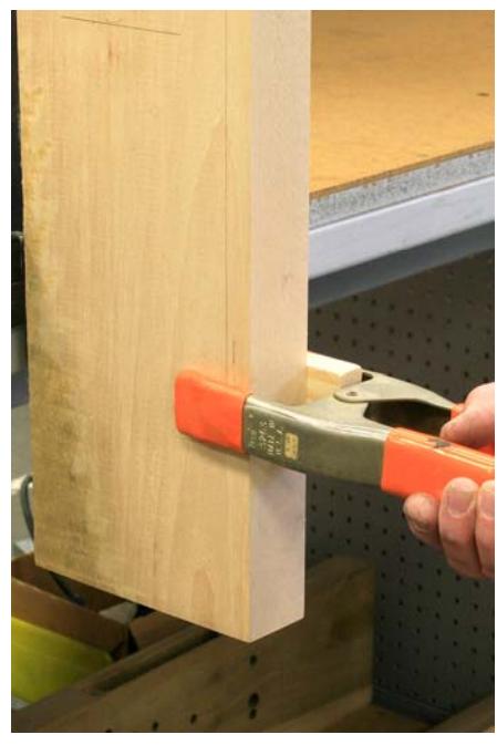
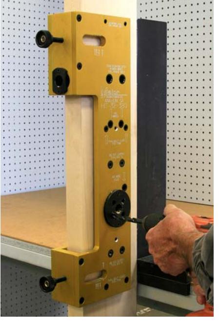
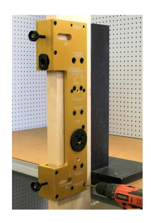
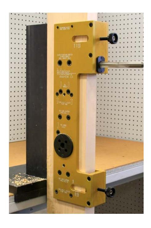
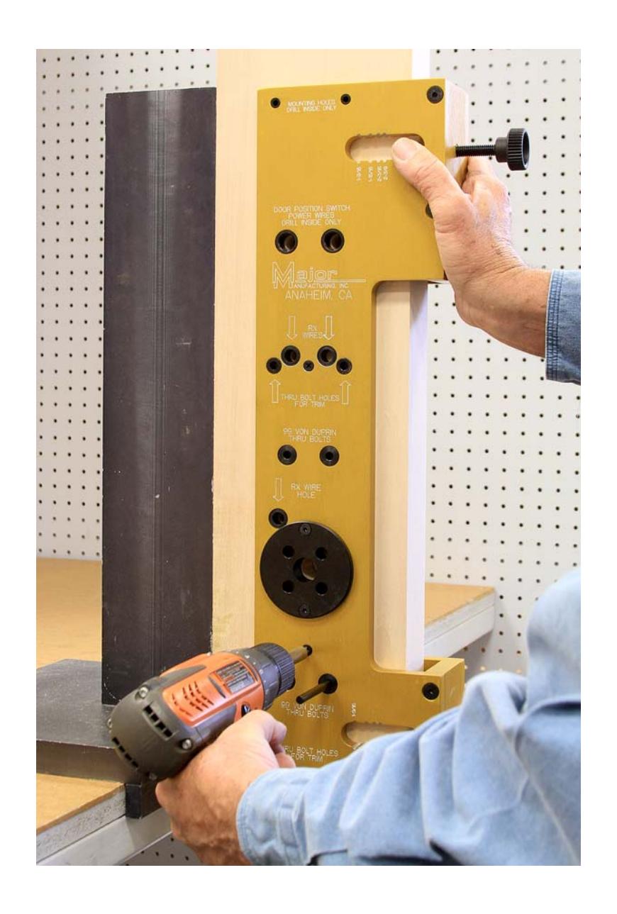
To help support the weight of this template, use a spring or "C" clamp as shown.
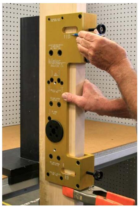
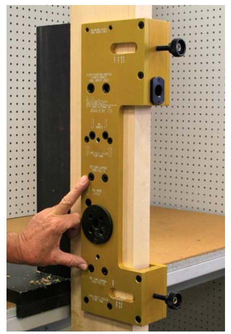
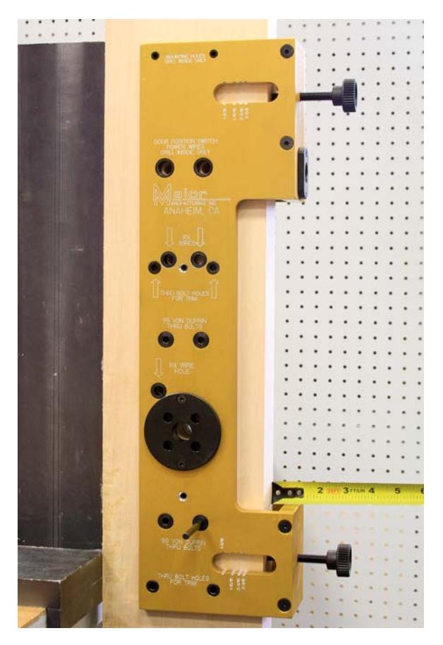
Backset lines are engraved in the template at the top and bottom at the viewing slots shown at left.
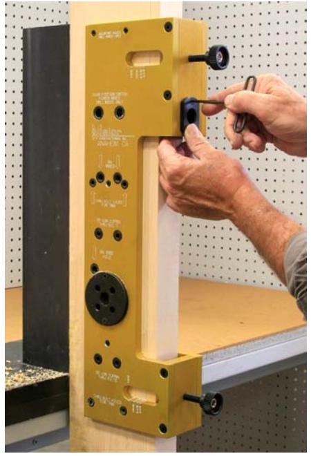
Determine the backset required for the strike that is being used and adjust the router guide with the alignment knobs. The backset that is required can be found in the Von Duprin instruction pages. For this install we have chosen 2-3/8" for a 299 strike.
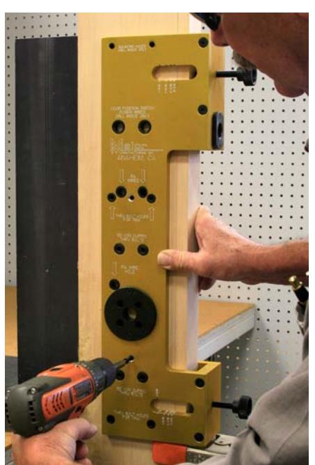
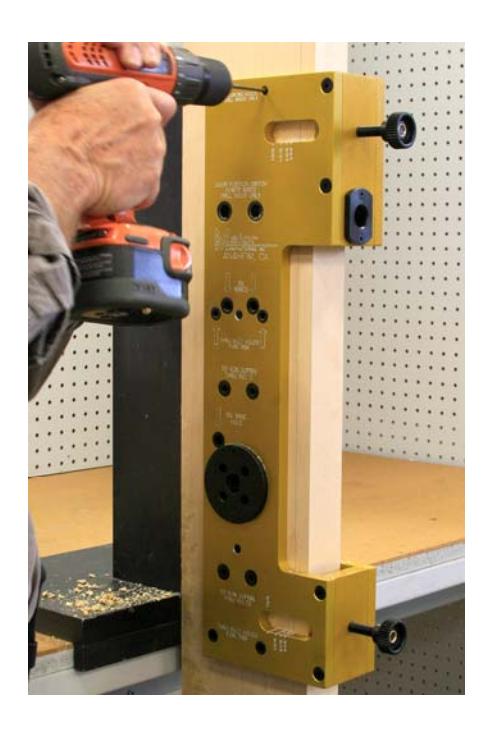
Attach the guide to the door with 2 of the supplied #6 dry wall screws. The attaching holes are counter sunk and are on both sides of the door. MOUNT THESE SCREWS ON THE INSIDE ONLY . Use a drill with a clutch system so you don't snap the screws off when they bottom out in the countersink. The screw holes will be covered by the head of the device after it is installed, they will not be visible.
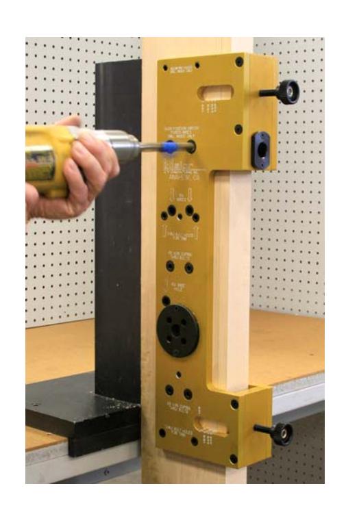
The drill guides on this jig will accept both twist drills and hole saws. For this wood door install we are using a brad point twist drill.
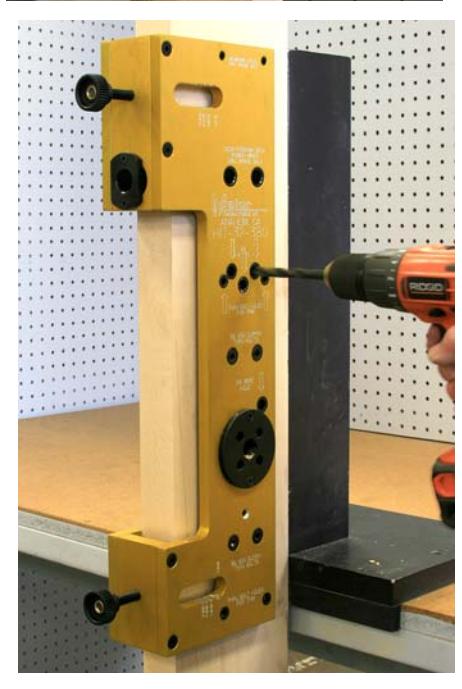
Drill the hole for the 99 spindle using a 3/4" bit. This hole is drilled half way from both sides of the door.
The two screws around the spindle on the outside trim will require a small relief so the trim will be flat on the door. Use a 3/8" drill bit and drill to a depth of about 1/4". This hole does not need to go to the mortise pocket, just dimpled.
There are 4 thru bolt holes for the 99 device, drill these holes with a 1/4" diameter drill bit half way from each side of the door.
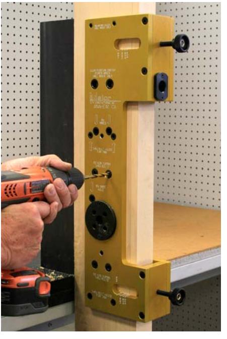
There are four drill guide bushings marked 99 Von Duprin thru bolts. Two at the bottom of the drill guide and two about 1/3 of the way down. Drill all four with a 1/4" drill bit half way from both sides of the door.
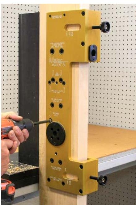
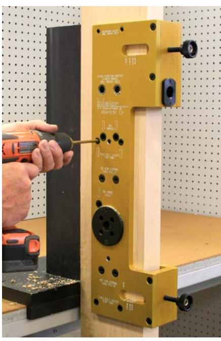
Drill the RX hole as shown with a 3/8" drill bit half way from both sides of the door. Note: The factory template shows a 13/32" Hole but a 3/8" works fine.
A second RX hole is needed as shown. Match this hole with the trim for the hand of the door. Drill with a 3/8" bit half way from both sides of the door.
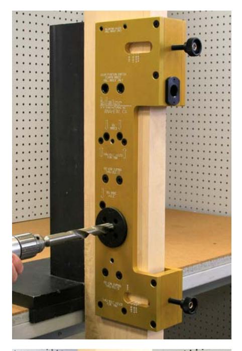
If using a door position switch, two holes will be needed on the INSIDE OF THE DOOR ONLY. Using the drill bushings marked door position switch, drill two 1/2" holes to a depth of 1-1/4". We used blue painters tape as a stop gauge, DO NOT DRILL THRU THE DOOR.
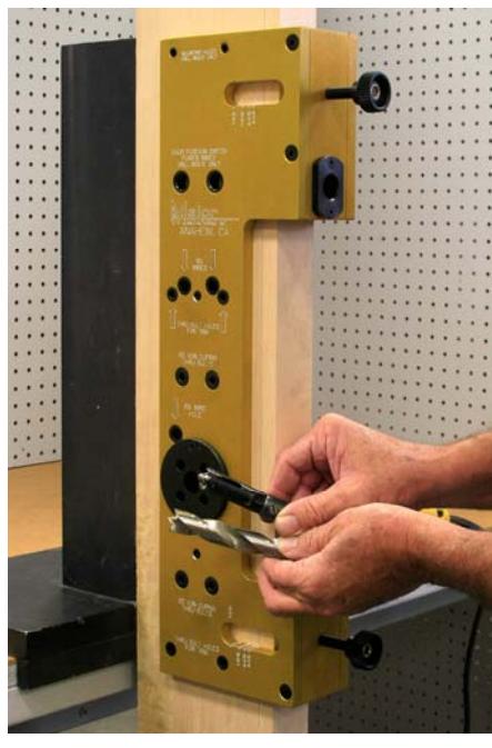
The drill bushing for the DPS on the edge of the door is adjustable for centering on a 1-3/4" door.
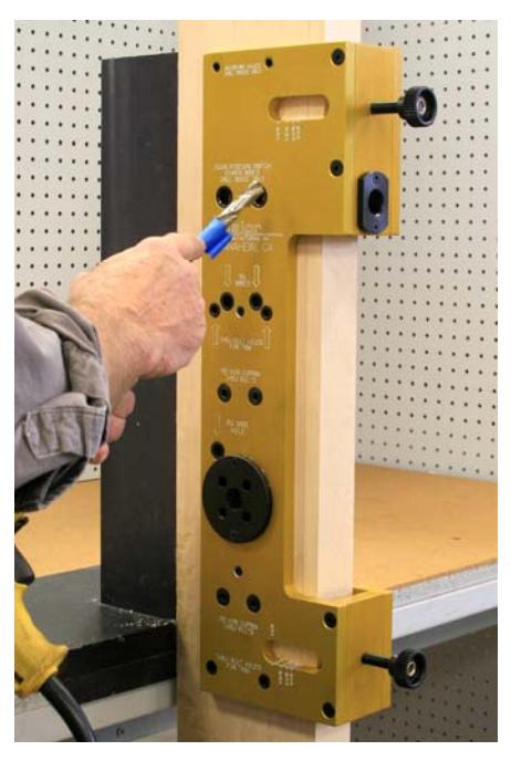
The DPS requires a 3/4" diameter hole. If drilling on a wood door use a brad point drill bit as shown. If installing on a steel door, use the 5/16" drill bushing adapter and twist drill. After the HIT-32-380 has been removed from the door, enlarge to 3/4" with the use of a step drill. DO NOT USE A HOLE SAW FOR THIS STEP, THE FINISHED HOLE WILL BE TOO BIG!!
Drill the centered 3/4" hole to the first DPS hole.
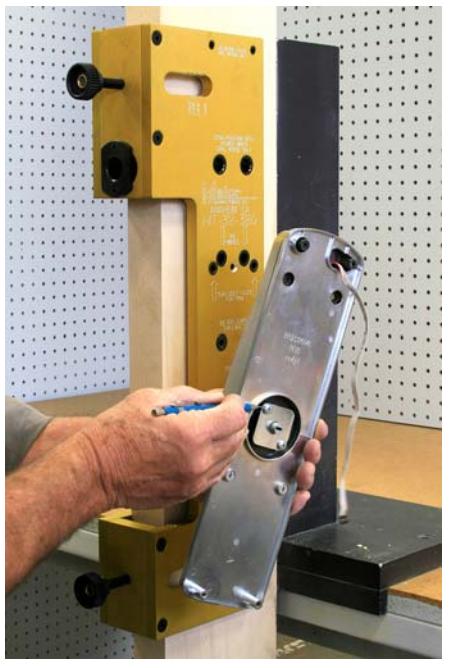
The last holes needed are for the control box located on the interior of the door. Drill two 5/32" holes to a depth of 1" on the inside of the door only.
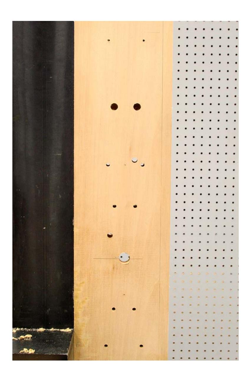
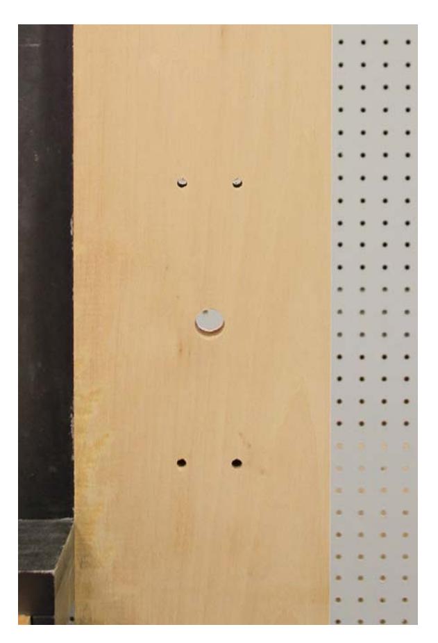
Interior view of completed installation.
For retrofitting an existing 99 Rim device see the next page.
After removing an existing 99 rim device the mounting holes can be used to align the HIT-32-380 drill guide.
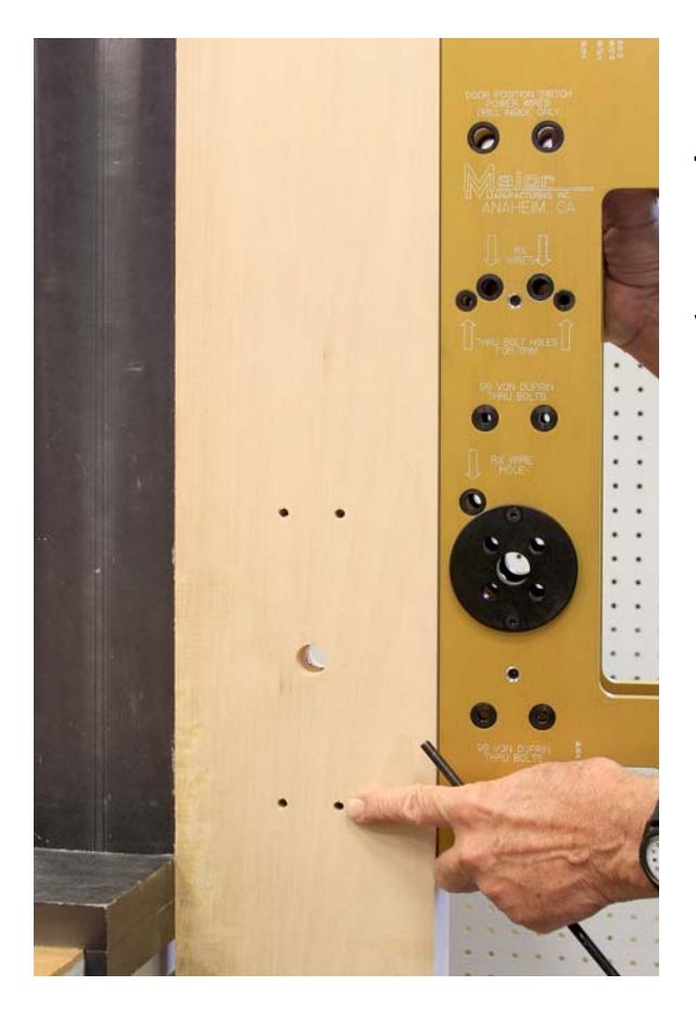
Choose any one of the four corner thru bolt holes and align with the supplied pin. Here we chose the lower RH hole.
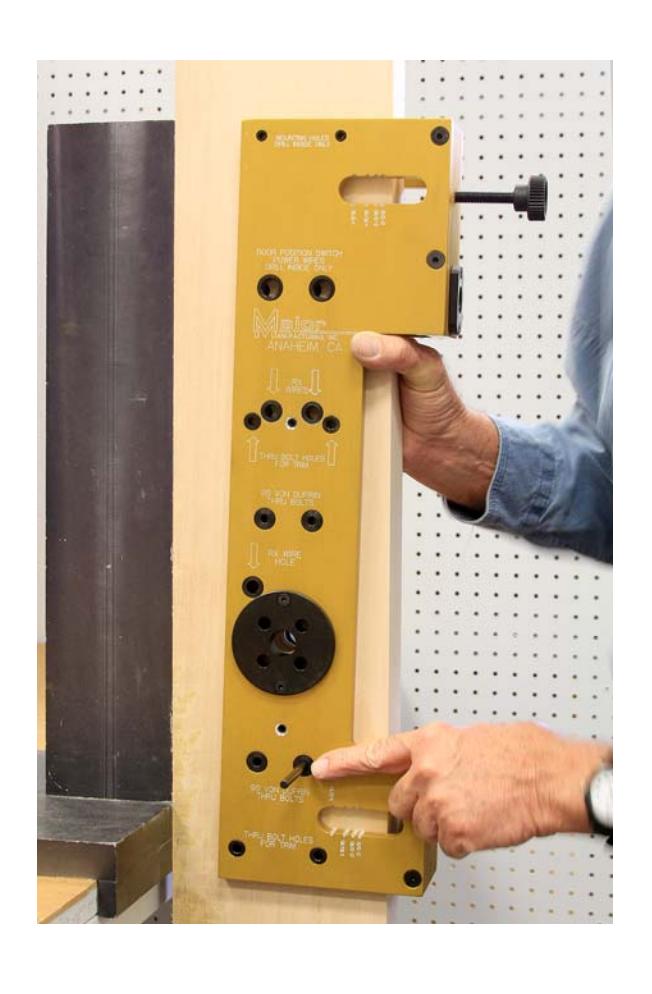
Slide the pin thru the corresponding drill guide hole and into the door. The pin does not need to go thru to the bushing on the other side.
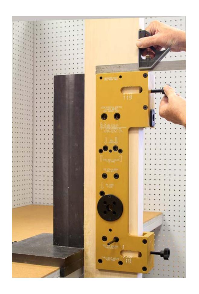
With the pin in the door, the backset and height are now set, Just use the two black knobs to square the device
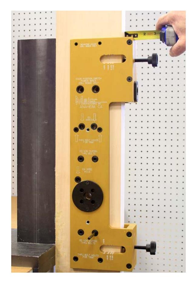
A tape measure or ruler may be used too. The top dimension needs to match the bottom dimension to be square.
Attach to door on the inside using two drywall screws. Use the directions starting on page 5 to install.