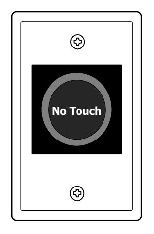
MODEL 474U – TOUCHLESS SENSE SWITCH INSTALLATION INSTRUCTION
Open the original PDF document
View PDF

INSTALLATION INSTRUCTIONS
INSTALLATION INSTRUCTIONS MODEL 474U - TOUCHLESS SENSE SWITCH
Installation & Operation
NOTE: The SDC 474 must be mounted to a single-gang electrical back box or plaster ring. All national and local codes must be followed in the installation of the 474U.
- 1. It is not necessary to remove the back cover. All connections should be terminated to the provided 5-pin wire harness.
- 2. Feed the low voltage wiring through the wall to the back box.
- 3. Connect the wires to the wiring harness using twist-on wire connectors, crimp connectors, or another acceptable connector (see page 2 for typical wiring examples).
- 4. Mount the stainless steel faceplate onto the back box using the two supplied screws. Be careful not to pinch any wires when mounting the device.
- 5. Apply 12 or 24 VDC power to the device. The LED indicator ring will turn RED.
- 6. Test for proper activation by placing a hand within a few inches of the sensor. The LED sensor ring will change from RED to GREEN, and the relay will activate.
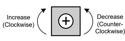
- 7. If necessary, adjust the read range of the sensor by carefully turning the blue potentiometer visible through the rear cutout of the 474U.
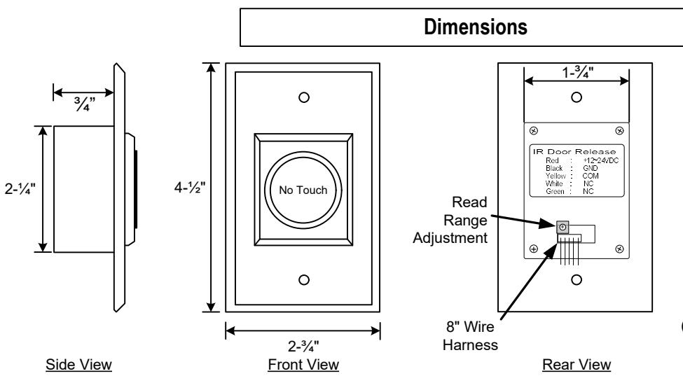
Dimensions
Features & Applications
- Uses Active IR sensor technology; device is activated with the simple wave of a hand
- Designed to control electric locks/strikes, magnetic locks, or automatic door operators
- Ideal for use in cleanrooms, hospitals, labs, schools, or offices
- Adjustable sensing range from 2" up to 7"
- Mounted on a durable stainless steel plate
- Dual LED, illuminated sensor indicates status
- 8-inch color coded wire harness for easy installation.
| Input Voltage | 12 or 24VDC | ||
|---|---|---|---|
| Current @ 12VDC 24VDC | 40mA Standby | 60mA Active | |
| Contact Rating | (1) Form C Relay, 3A@30VDC (Resistive) | ||
| LED Color | Standby | Red | |
| Active | Green | ||
| Read Range | Adjustable (2"-7") | ||
|
Output Activation
Time |
1 Second or as long as sensor is triggered | ||
| Operating Temp. | -4deg F ~ 131deg F (-20C ~ 55C) | ||
| Weight | 3 oz. (85g) | ||
Specifications
Wiring Details
+12~24VDC Red Power GND Black Yellow COM Relay White NC: Output Green
4.5" X 2.75" x 1.375"
Read Range Adjustment
NOTE: Carefully use a small phillips head screwdriver to turn blue pot, 1/4 turn at a time

[t] 800.413.8783 ■ 805.494.0622 ■ [f] 805.494.8861 ■ 801 Avenida Acaso, Camarillo, CA 93012 ■ PO Box 3670, Camarillo, CA 93011
Typical Wiring Examples
Example 1: Connecting the 474U to an Automatic Door Operator
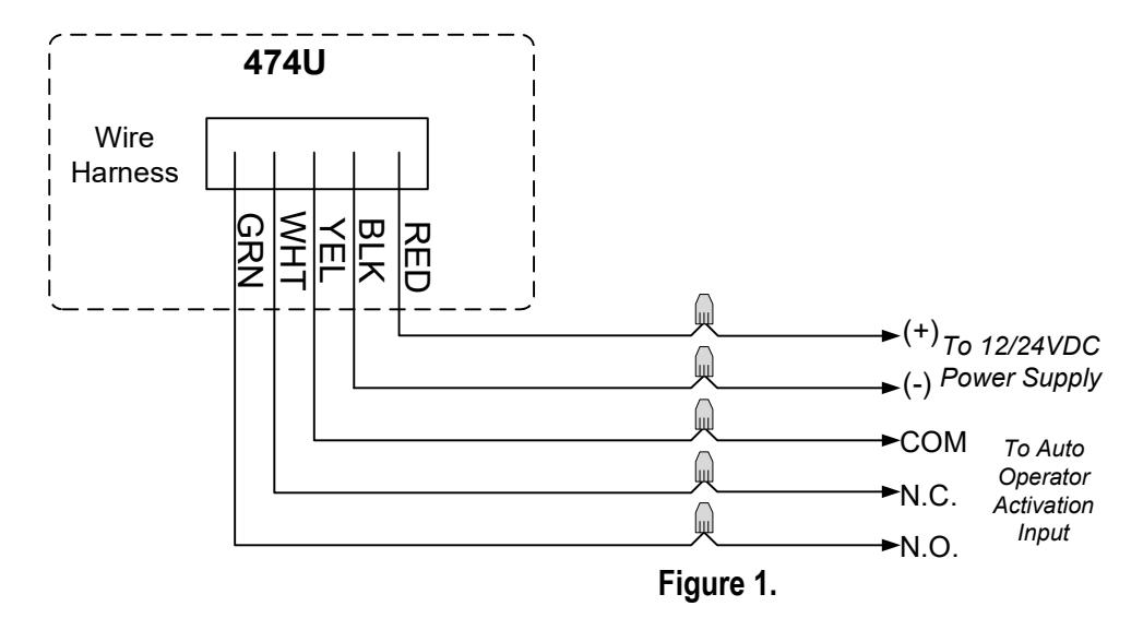
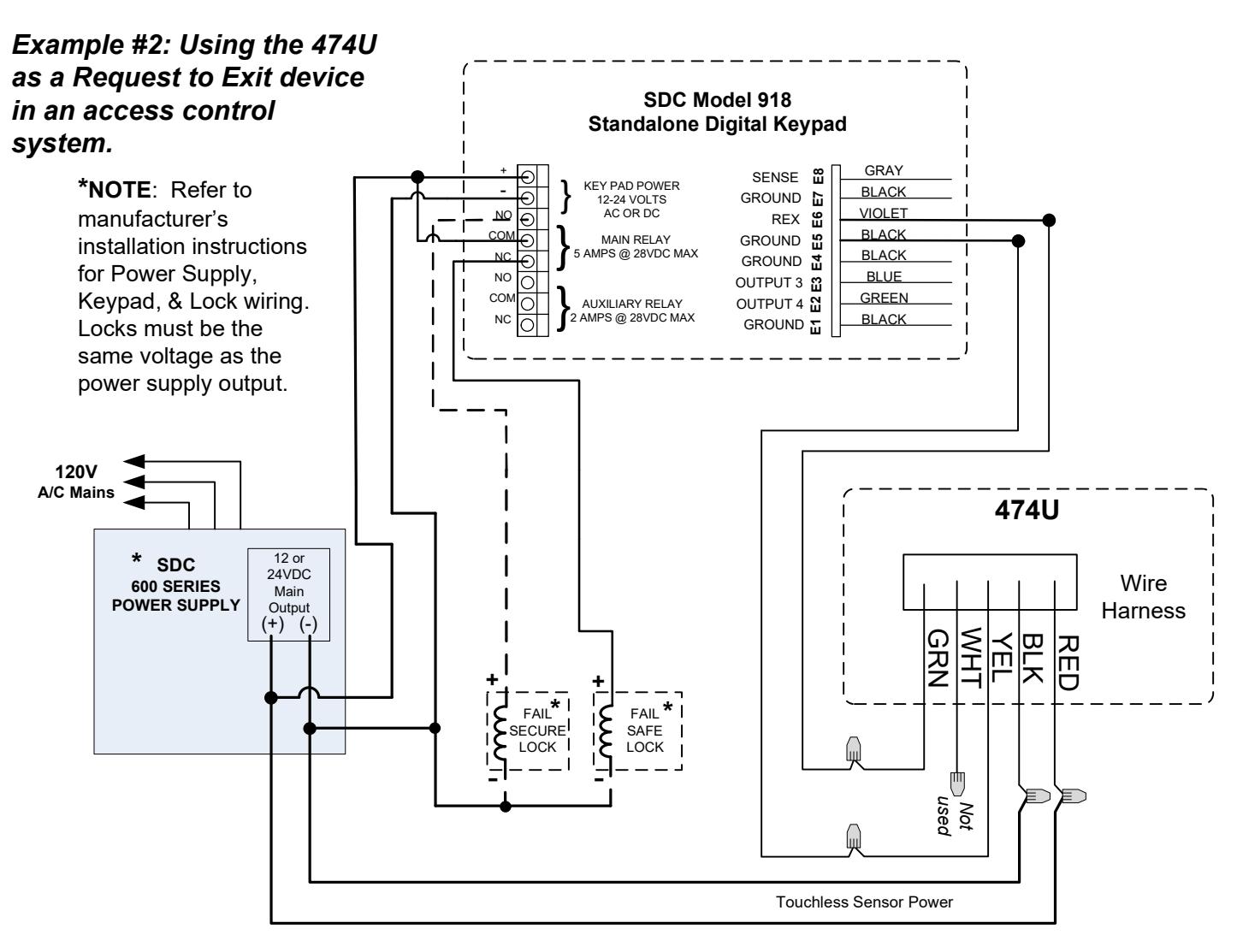
Figure 2.