MLRK1-VD Insert Instructions
Open the original PDF document
View PDF


MLRK1-VD

INSERT INSTRUCTIONS
The Command Access MLRK1 is a field installable motorized latch-retraction kit for:
- MLRK1-VD Von Duprin 98/99 & 33/35 series devices
- MLRK1-VDAX Von Duprin 98/99AX & 33/35AX series devices
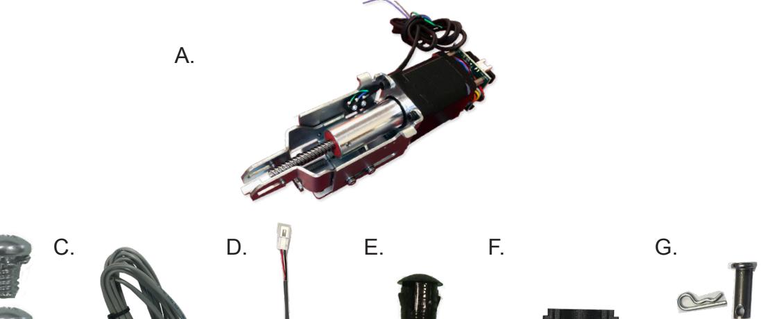
KIT INCLUDES
- A. 1- MOTOR MOUNT W/MM5
- B. 2-40002 8/32 X 1/4" PHILLIPS HEAD SCREW
- C. 1-50030 8/ LEAD W/ VD CONNECTOR
- D. 1-50944 MOLEX PIGTAIL
- E. 1-40144 DOGGING HOLE CAP
FIRE RATED DOGGING KIT
- F. 1-50991 FIRE RATED DRILLING TEMPLATE (OLD BASERAILS)
- G. 1-REPLACEMENT DOGGING TAIL PIECE (40006 + 408000+50991)

INSTALLATION VIDEO
SPECIFICATIONS
- INPUT VOLTAGE: 24VDC +/- 10%
- AVERAGE LATCH RETRACTION CURRENT: 900 MA
- AVERAGE HOLDING CURRENT: 215 MA
- WIRE GAUGE: MINIMUM 18 GAUGE
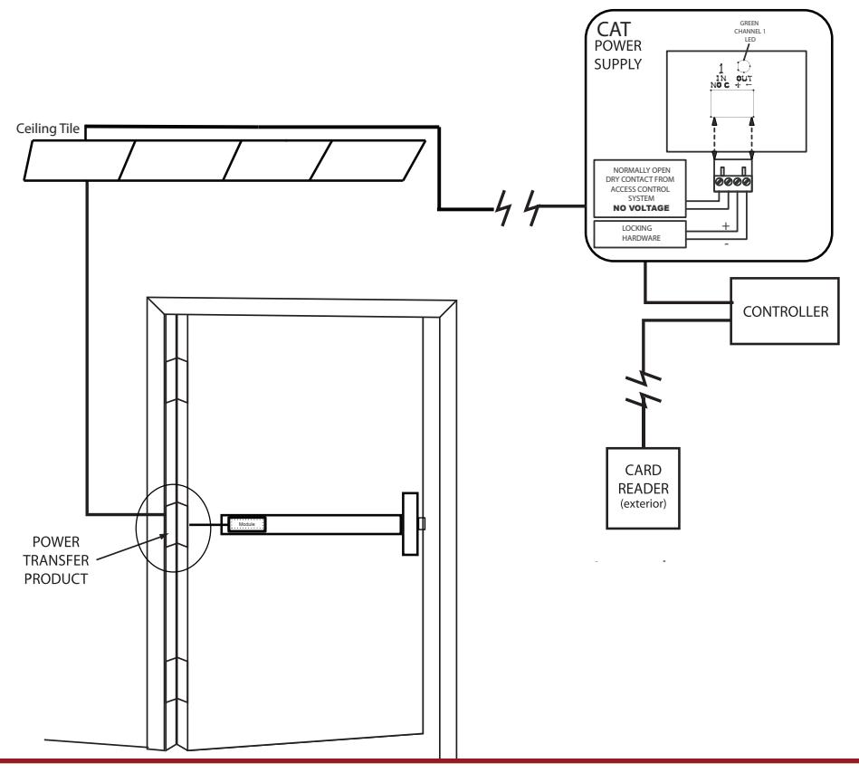
- DIRECT WIRE RUN NO RELAYS OR ACCESS CONTROL UNITS IN-BETWEEN POWER SUPPLY & MODULE
BUILT-IN REX
- SPDT RATED .5A @24V
- GREEN= COMMON (C)
- BLUF = NORMALLY OPEN (NO)
- GREY = NORMALLY CLOSED (NC)
RECOMMENDED POWER SUPPLIES: USE A POWER LIMITED CLASS 2 POWER SUPPLY
ALL COMMAND ACCESS EXIT DEVICES & FIELD INSTALLABLE KITS HAVE BEEN THOROUGHLY CYCLE TESTED WITH COMMAND ACCESS POWER SUPPLIES AT OUR FACTORY. IF YOU PLAN ON USING A NON-COMMAND POWER SUPPLY IT MUST BE A FILTERED & REGULATED LINEAR POWER SUPPLY.
Technical Information

Setting PUSH TO SET (PTS)
Make sure to set PTS before finishing installation


Troubleshooting & Diagnostics
| Beeps | Explanation | Solution |
|---|---|---|
| 2 Beeps | Over Voltage | > 30V unit will shut down. Check voltage & adjust to 24 V. |
| 3 Beeps | Under Voltage | < 20V unit will shut down. Check voltage & adjust to 24 V. |
| 4 Beeps | Failed Sensor |
Verify all 3 sensor wires are installed correctly. Replace sensor if
problem persists by contacting office. |
| 5 Beeps | Retraction or dogging failure | After 1st fail: 5 beeps then immediately attempts to retract again. |
|
After 2nd fail: 5 beeps with pause in-between for 30 seconds then device
attempts to retract again. |
||
| After 3rd fail: 5 beeps every 7 minutes, device will not attempt to retract. | ||
| To Reset: Depress bar for 5 seconds at any time. |

INSTALLATION INSTRUCTIONS

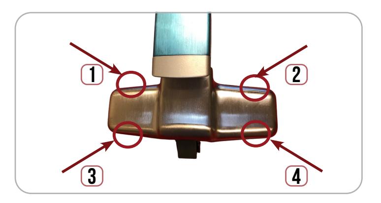
1 Remove (4) screws from Head Cover .
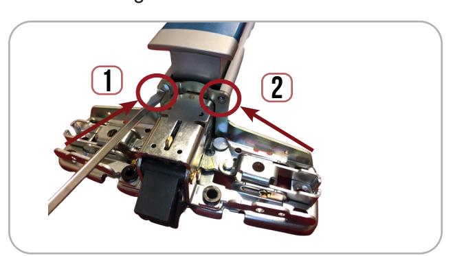
2. Remove (2) Screws securing mounting bracket to housing.
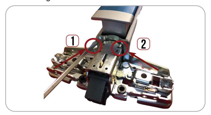
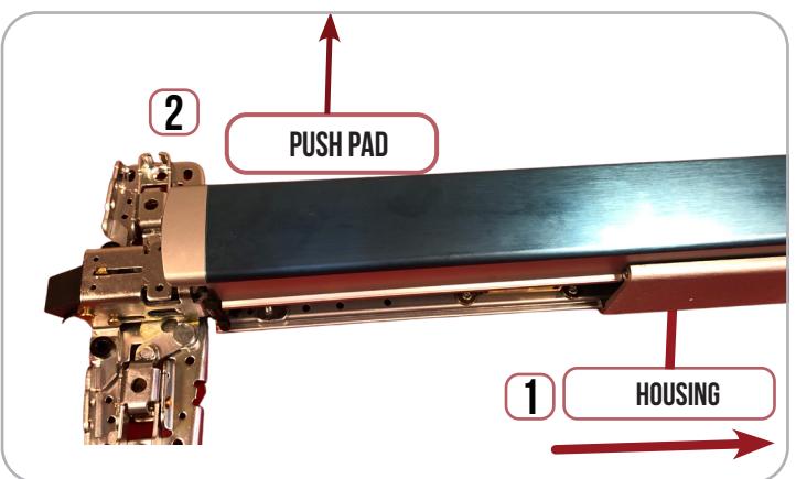
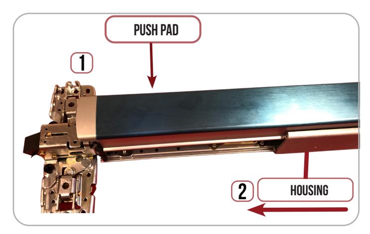
3. Slide off (1) Housing to expose Pushpad & Baserail Assembly. Next, (2) remove push pad.
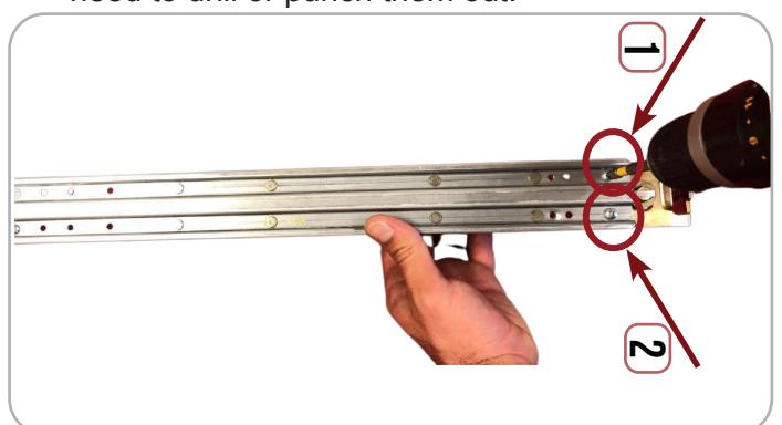
4. If your device has Mechanical Dogging , flip Baserail over & remove (2) screws securing dogging to Baserail. If you have rivets, you will need to drill or punch them out.
FIRE RATED DEVICES ONLY - NON-RATED SKIP TO STEP 7
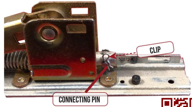
5. Use Replacement Dogging Tail (50872), & insert into the connection rod.
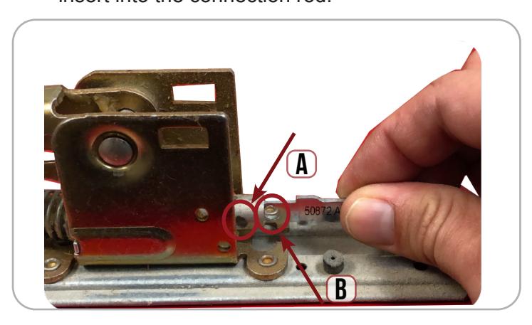
6. Line up Holes A & B, insert pin & secure it with the clip provided. If you have an older device without Hole B, please scan the QR code for a video how to use the provided dogging kit.

I n s ta l l at i o n I n s t r u c t i o n s

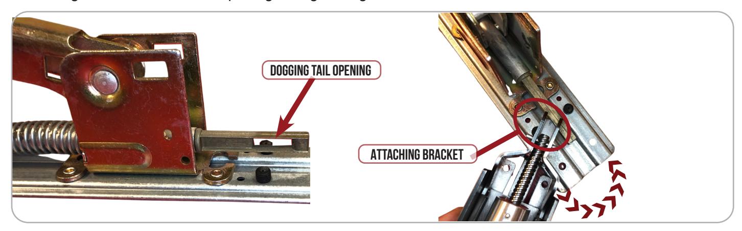
The attaching bracket on your motor kit will slide into the dogging tail opening at a slight angle. Once the 7. attaching bracket is inside the opening, straightening the motor kit.
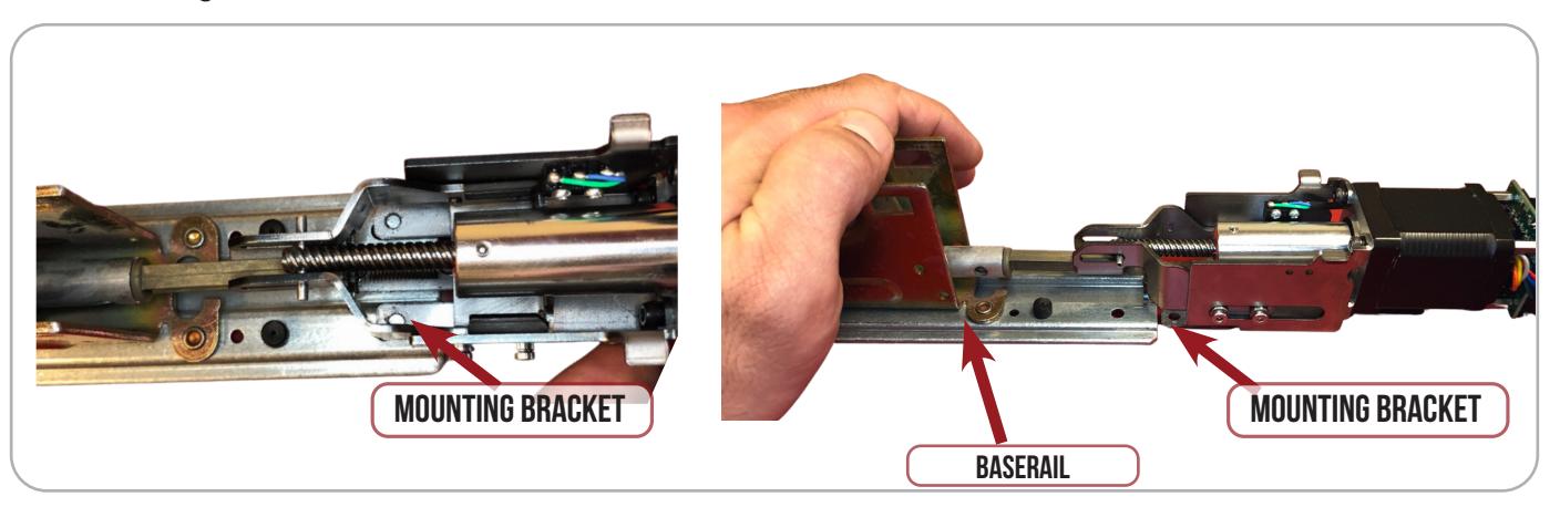
Straighten Motor kit , depress the back activating bracket & gently pull back on the motor kit to slide 8. the mounting bracket UNDERNEATH the baserail.
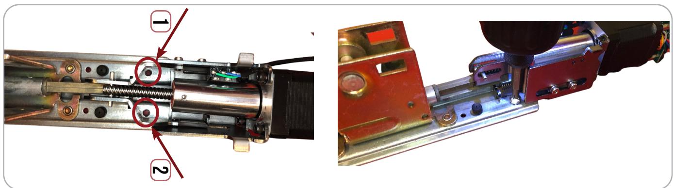
9. Line up mounting bracket holes with existing holes on baserail. Secure Motor kit to baserail by installing (2) screws provided from the top of the device, not from underneath.

INSTALLATION INSTRUCTIONS

10. Test Motor kit on baserail to confirm it is function properly.
11. Re-install Push Pad (1) , then slide the exit device housing back onto the device (2).
12. Re-install Mounting Bracket , to secure the housing to the device.
13. Now, set the motor adjustment by following the Push to Set directions below.
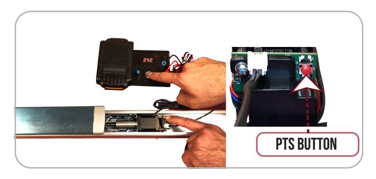
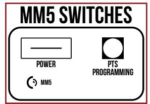
SETTING PUSH TO SET (PTS)
→ **IMPORTANT INFO** ←
MAKE SURE TO SET PTS BEFORE FINISHING INSTALLATION
- STEP 1 - To enter PTS mode: Depress MM5 button & apply power. The device will emit 1 SHORT beep. The device is now in PTS mode.
- STEP 2 - While depressing the push pad, apply power. (i.e. presenting the credential to the reader).
- STEP 3 Continue to keep pad depressed, the device will emit 1 LONG Beep. After the beep has stopped, release the pad and now the adjustment is complete, test the new location, If not to your liking repeat the 3 steps.

MM5 SWITCHES POWER PTS PROGRAMMING (5) MM5