MLRK1- TEL
Open the original PDF document
View PDF


MLRK1
INSERT INSTRUCTIONS
The Command Access MLRK1 is a field installable motorized latch-retraction kit for:
- MLRK1-TEL Tell 9500 series devices
- MLRK1-TTN Phoenix Titan 66 series devices
- MLRK1-PHI Philadelphia Hardware 9000 series devices
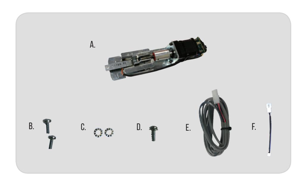
KIT INCLUDES TOOLS REQUIRED
1 - 60281 - MLRK1
B. 2 - 40786 - M4 screws
C. 2 - 40351 - Lock Washers
D. 1 - 40014 - Phillips Screw with Lock washer
E. 1 - 50030 - 8' Lead
F. 1 - 50944 - MM4T Socket Lead
A. Cordless Drill or Phillips Screwdriver
TECHNICAL INFORMATION

SPECIFICATIONS
Input Voltage: 24VDC +/- 10% Wire gauge: Minimum 18 gauge
Direct wire run - no relays or access control units in-between power supply & module
STANDARD TORQUE MODE
Average Latch Retraction Current: 900 mA Average Holding Current: 215 mA
HIGH TORQUE MODE
Average Latch Retraction Current: 2 Amp Average Holding Current: 250 mA
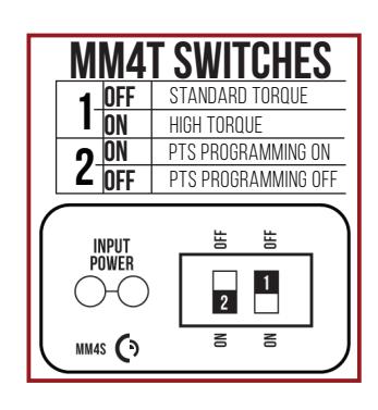
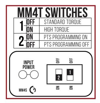
SETTING PTS → **IMPORTANT INFO** ←
MAKE SURE TO SET PTS BEFORE FINISHING INSTALLATION
- STEP 1 - Select your preferred torque mode (ships in standard torque). Press the device push pad to the desired setting. (We recommend to fully depress and release 5%, giving the device room for changing door conditions.)
- STEP 2 - While depressing the push pad, apply power. (i.e. presenting the credential to the reader).
- STEP 3 Continue to keep the pad depressed, the device will beep 6 times. After the beeps have stopped, release the pad and the adjustment is now complete. If not to your liking repeat the 3 steps.
TROUBLESHOOTING & DIAGNOSTICS
| BEEPS | EXPLANATION | SOLUTION |
|---|---|---|
| 2 Beeps | Over Voltage | > 30V unit will shut down. Check voltage & adjust to 24 V. |
| 3 Beeps | Under Voltage | < 20V unit will shut down. Check voltage & adjust to 24 V. |
| 4 Beeps | Failed Sensor | Verify all 3 sensor wires are installed correctly. Replace sensor if problem persists by contacting office. |
| 5 Beeps | Retraction or dogging failure | After 1st fail: 5 beeps then immediately attempts to retract again. After 2nd fail: 5 beeps with pause in-between for 30 seconds then device attempts to retract again. After 3rd fail: 5 beeps every 7 minutes, device will not attempt to retract. To Reset: Depress bar for 5 seconds at any time. |
| 6 Beeps | PUSH TO SET | Device is recording it's new position and power mode after the 6th beep. |

*Latch bolt adjustment- If the latch bolt is not retracting far enough, turn the dial clockwise with a small flat blade screw driver. If the latch bolt is retracting too far causing the device to chatter and drop-out, turn the dial counter-clockwise until the chatter and drop-outs stop and the desired location is achieved.
ELECTRIFIED EXIT DEVICE
Installation Example

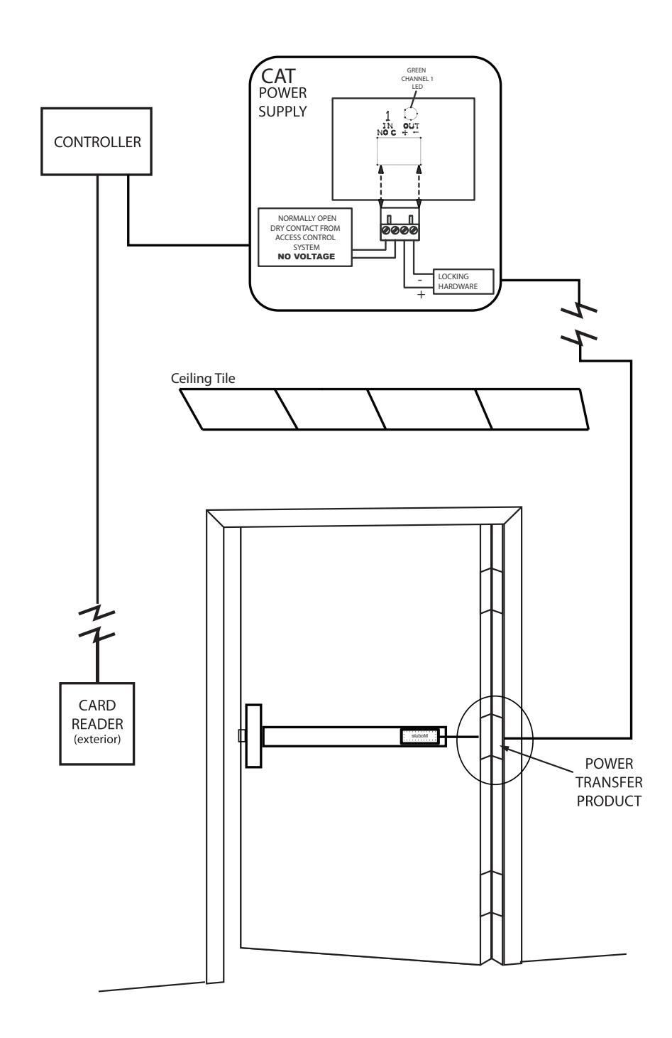
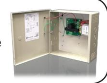
Recommended Power Supplies:
All Command Access exit devices & field installable kits have been thoroughly cycle tested with Command Access power supplies at our factory.
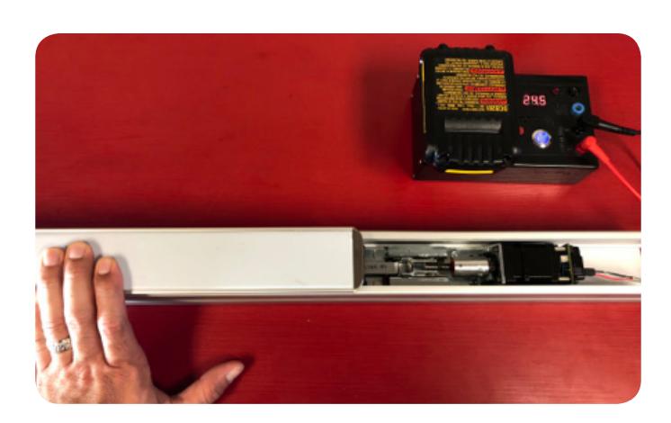
INSTALLATION INSTRUCTIONS

- SLIDE HOUSING OFF TO REVEAL BASERAIL. YOU MAY HAVE TO REMOVE TWO SCREWS FROM UNDERSIDE OF HOUSING BEFORE SLIDING OFF. 1.
- IF YOUR DEVICE HAS DOGGING, YOU NEED TO REMOVE BOTH SCREWS FROM CONNECTING ROD. 2.

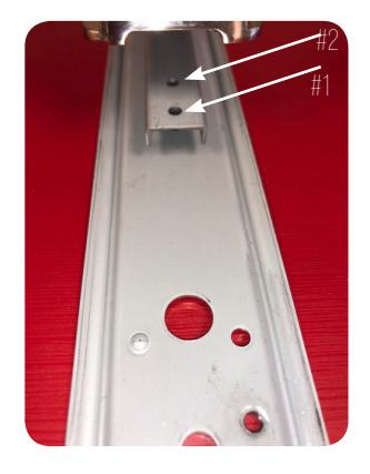
For hole #2, you'll need to start loosing it by using vise grips or a needle nose pliers & work the screw loose.
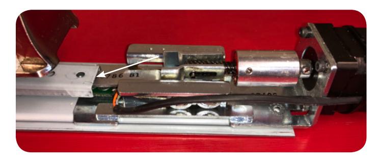
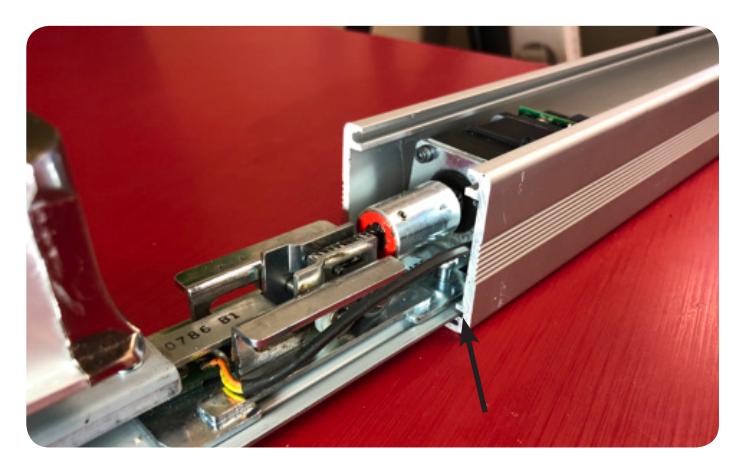
- INSTALL KIT ON TOP OF BASERAIL & ATTACHING BRACKET, SLIDING UNDERNEATH THE CONNECTING ROD. 3.
- THE KIT WILL LINE UP WITH THE EXISTING SCREW HOLES ON THE BASERAIL & 1ST SCREW HOLE ON THE CONNECTING ROD. 4.
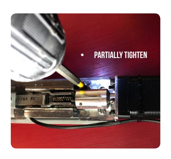
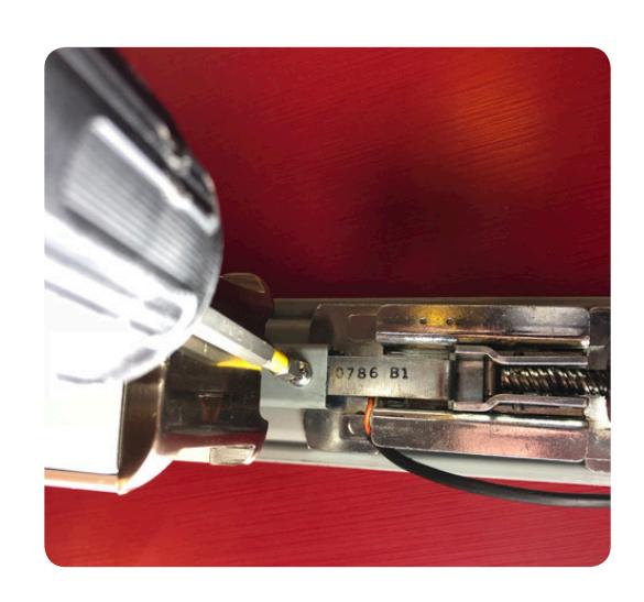
INSTALL BOTH (40786) SCREWS & (40351) LOCK WASHERS PARTIALLY, SO THE BASERAIL CAN STILL SLIDE BACK INTO THE HOUSING. 5.
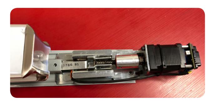
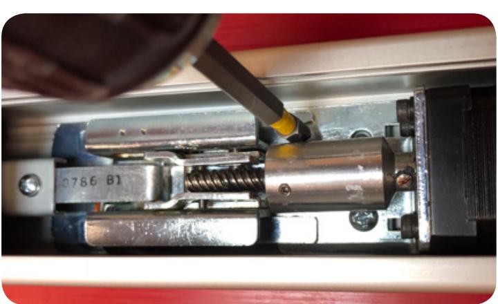
INSTALL (40064) SCREW TO SECURE ATTACHING BRACKET TO CONNECTING ROD 6.
INSTALLATION INSTRUCTIONS

7. SLIDE BASERAIL WITH MOTOR KIT BACK INTO HOUSING. MAKE SURE IT'S IN THE MIDDLE CHANNEL!

9. NEXT, HOOK UP TO POWER AND SET THE PUSH-TO-SET ADJUSTMENT. FOLLOW STEPS BELOW TO SET, REMEMBERING TO TURN THE PROGRAMMING SWITCH TO THE OFF POSITION WHEN COMPLETED.
SETTING PTS
- STEP 1- Select your preferred torque mode (ships in standard torque) Press the device push pad to the desired setting. (Recommend to fully depress and release 5%, giving the device room for changing door conditions.)
- STEP 2- While depressing the push pad, apply power. (i.e. presenting the credential to the reader).
- STEP 3- Continue to keep pad depressed, the device will beep 6 times. After the beeps have stopped, release the pad and now the adjustment is complete. If not to your liking repeat the three steps.
- STEP 4- Once you found the correct location, flip the dip switches to off to lock programming.