MLRK1-MRK8 Insert Instructions
Open the original PDF document
View PDF


mlrk1-MRK8


INSERT INSTRUCTIONS
The Command Access MLRK1 is a field installable motorized latch-retraction kit for: • MRLK1-MRK8 - Marks M8800 Series


Kit Includes
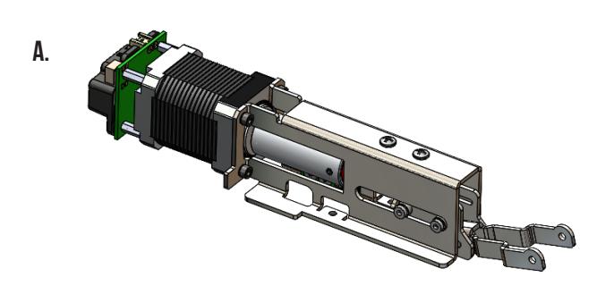
- A. (1) 60728 MLRK1-MRK8
- B. (1) 51222 Connecting Bracket
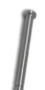
- C. (1) 51048 Connecting pin
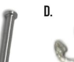
- D. (3) 40067 E-CLip
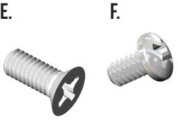
- E. (2) 40064 M4 x 10mm Phillips Flat Head Screw
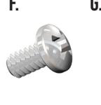
- F. (1) 40073 6-32 x 1/4 Phillips pan head screw
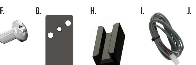
- G. (1) 51263 MOTOR KIT spacer
- H. (4) 52084 PAD SPACER
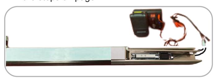
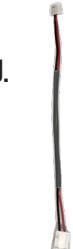
- I. (1) 50030 8' Lead w/ VD Connector
- J. (1) 50944 MOLex pigtail
SPECIFICATIONS
- Input Voltage: 24VDC +/- 10%
- AVERAGE low Torque LATCH RETRACTION CURRENT: 900 mA
- Average high torque latch retraction current: 2A
- Average holding current: 215 ma
- Wire gauge: Minimum 18 gauge
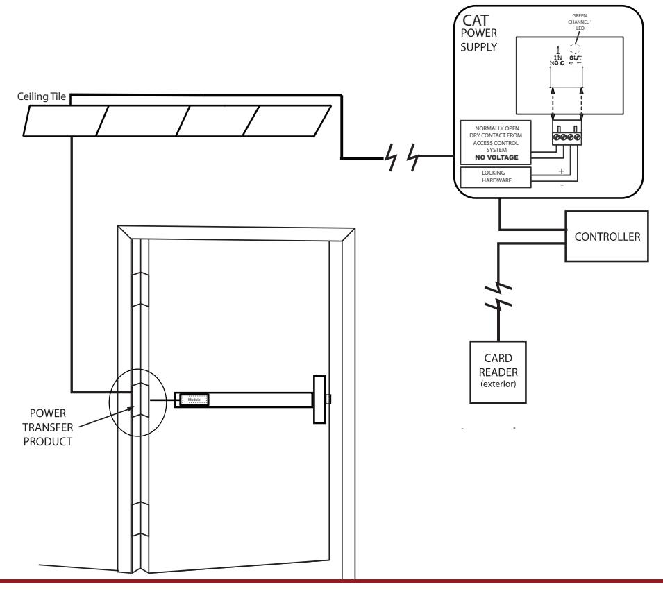
- Direct wire run no relays or access control units in-between power supply & module
Recommended Power Supplies: Use a power limited class 2 power supply
All Command Access exit devices & field installable kits have been thoroughly cycle tested with Command Access power supplies at our factory. If you plan on using a non-Command power supply it must be a filtered & regulated linear power supply.
• SPDT - Rated .5a @24V • green= Common (C)
• Blue = normally open (NO) • grey = normally closed (NC)
Optional built-in rex
TECHNICAL INFORMATION

SETTING PUSH TO SET (PTS)
→ MAKE SURE TO SET PTS BEFORE FINISHING INSTALLATION <
- STEP 1- SELECT YOUR PREFERRED TORQUE MODE (SHIPS IN STANDARD TORQUE) PRESS THE DEVICE PUSH PAD TO THE DESIRED SETTING. (RECOMMEND TO FULLY DEPRESS AND RELEASE 5%, GIVING THE DEVICE ROOM FOR CHANGING DOOR CONDITIONS.)
- STEP 2- WHILE DEPRESSING THE PUSH PAD, APPLY POWER. (I.E. PRESENTING THE CREDENTIAL TO THE READER).
- STEP 3- CONTINUE TO KEEP PAD DEPRESSED, THE DEVICE WILL BEEP 6 TIMES . AFTER THE BEEPS HAVE STOPPED, RELEASE THE PAD AND NOW THE ADJUSTMENT IS COMPLETE. IF NOT TO YOUR LIKING REPEAT THE 3 STEPS.
- STEP 4- ONCE YOU FOUND THE CORRECT LOCATION, TURN PTS SWITCH TO OFF POSITION.
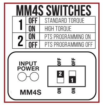
MM4S SWITCHES 1 OFF STANDARD TORQUE ON HIGH TORQUE ON PTS PROGRAMMING ON OFF PTS PROGRAMMING OFF INPUT POWER OMASS & STANDARD TORQUE INPUT B PROGRAMMING OFF MM4S & S
TROUBLESHOOTING & DIAGNOSTICS
| BEEPS | EXPLANATION | SOLUTION |
|---|---|---|
| 2 BEEPS | OVER VOLTAGE | > 30V UNIT WILL SHUT DOWN. CHECK VOLTAGE & ADJUST TO 24 V. |
| 3 BEEPS | UNDER VOLTAGE | < 20V UNIT WILL SHUT DOWN. CHECK VOLTAGE & ADJUST TO 24 V. |
| 4 BEEPS | FAILED SENSOR | VERIFY ALL 3 SENSOR WIRES ARE INSTALLED CORRECTLY. REPLACE SENSOR IF PROBLEM PERSISTS BY CONTACTING OFFICE. |
| AFTER 1ST FAIL: 5 BEEPS THEN IMMEDIATELY ATTEMPTS TO RETRACT AGAIN. | ||
| 5 BEEPS | RETRACTION OR DOGGING FAILURE | AFTER 2ND FAIL: 5 BEEPS WITH PAUSE IN-BETWEEN FOR 30 SECONDS THEN DEVICE ATTEMPTS TO RETRACT AGAIN. |
| AFTER 3RD FAIL: 5 BEEPS EVERY 7 MINUTES, DEVICE WILL NOT ATTEMPT TO RETRACT. | ||
| TO RESET: DEPRESS BAR FOR 5 SECONDS AT ANY TIME. | ||
| 6 BEEPS | PUSH TO SET | DEVICE IS RECORDING IT'S NEW POSITION AND POWER MODE AFTER THE 6TH BEEP. |

INSTALLATION INSTRUCTIONS

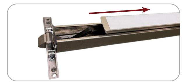
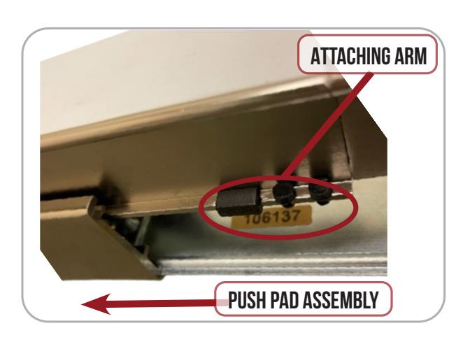
1. Slide off push pad assembly from exit device.
2. Remove Dogging Assembly if present & install (G) Spacer over existing holes.
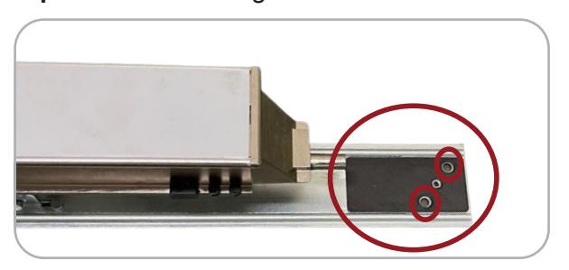
3. Line up Mounting Holes on Motor Kit with screw holes on Spacer/Base Rail.
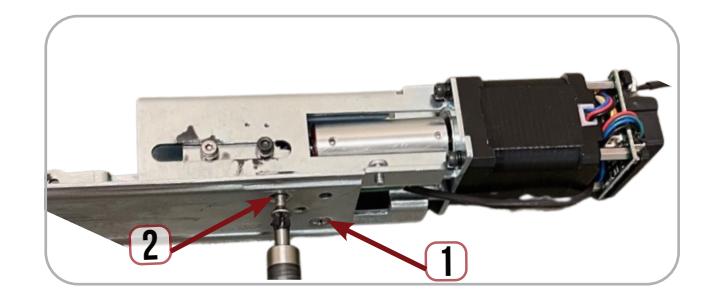
4. Turn full assembly to the side & install (E) Screws from underneath to secure motor kit to Base Rail.
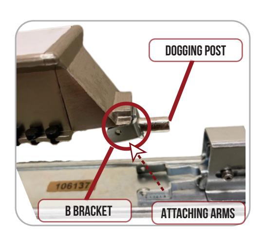
5. Slide the (B) Connecting Bracket over the Dogging post at the end of the push pad. Next, move Attaching Arms on motor kit up to line up with holes on B Bracket.
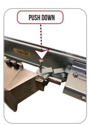
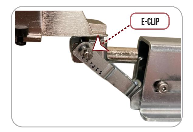
6. Once Attaching Arms are lined up insert (C) PIN to connect to (B) bracket.

INSTALLATION INSTRUCTIONS

7. Install the (D) E-CLIP over the end of the link pin to secure.
8. Swap the existing spacers with the (H) PAD SPACER on both sides of push pad next to rubber bumpers to connect to (B) bracket.
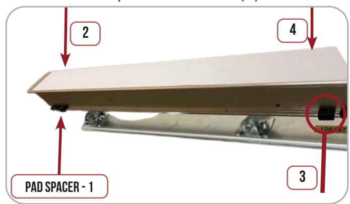
9. Re-install the Push Pad Assembly into the exit device housing, keeping an eye on the push pad spacer & rubber bumpers.
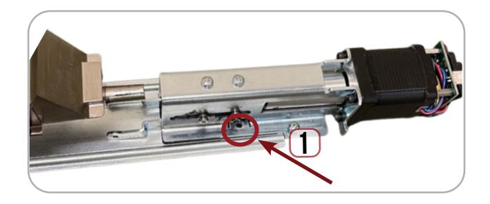
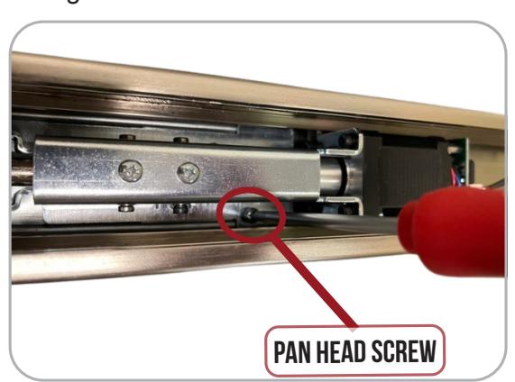
10. Locate the hole on the underside of the device and line up the hole with the tapped hole in the base rail
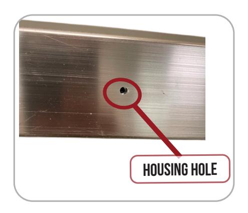
Locate and install the position set screw (F) Pan Head Screw, to secure push pad assembly to housing.
12. Set the " Push to Set Adjustment " following the steps on page 2.