MLRK1-KAWP Insert Instructions
Open the original PDF document
View PDF


MLRK1-KAWP


INSERT INSTRUCTIONS
The Command Access MLRK1-KAWP is a field-installable motorized latch-retraction kit for the Kawneer Paneline series exit devices.
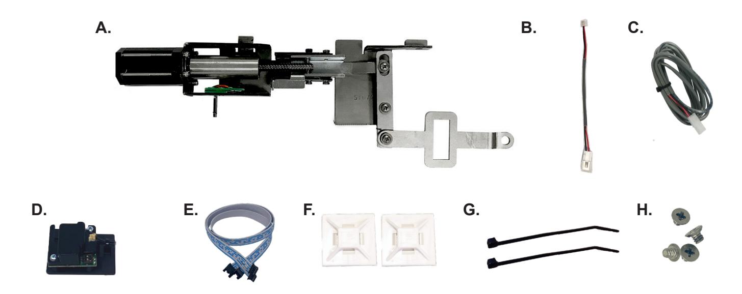
KIT INCLUDES
- A. 60417 MLRK1 MOTOR
- B. 50944 MOLEX PIGTAIL
- C. 50030 6' POWER CABLE
- D. 60708/51186 MM4T REMOTE MODULE
- E. 51198 REMOTE MODULE CABLE
- F. 40059 (X2) CABLE MOUNTING PAD
- G. 40060 (X2) CABLE TIES
- H. 40306 PHILLIPS SCREWS (X4)

SPECIFICATIONS
- INPUT VOLTAGE: 24-25.3VDC
- AVERAGE LOW TOROUE LATCH RETRACTION CURRENT: 900 MA
- AVERAGE HIGH TORQUE LATCH RETRACTION CURRENT: 2A
- AVERAGE HOLDING CURRENT: 215 MA
- WIRE GAUGE: MINIMUM 18 GAUGE
- DIRECT WIRE RUN NO RELAYS OR ACCESS CONTROL UNITS IN-BETWEEN POWER SUPPLY & MODULE
REQUIRED COMMAND POWER SUPPLIES: USE A PS210/220/440B
ALL COMMAND ACCESS EXIT DEVICES & FIELD INSTALLABLE KITS HAVE BEEN THOROUGHLY CYCLE TESTED WITH COMMAND ACCESS POWER SUPPLIES AT OUR FACTORY, IF YOU PLAN ON USING A NON-COMMAND POWER SUPPLY IT MUST BE A FILTERED & REGULATED LINEAR POWER SUPPLY.
OPTIONAL BUILT-IN REX
- SPDT RATED .5A @24V
- GREEN= COMMON (C)
- BLUE = NORMALLY OPEN (NO)
- GREY = NORMALLY CLOSED (NC)

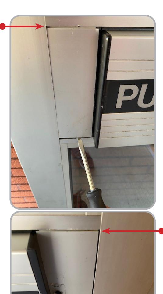
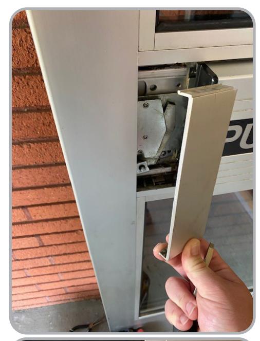
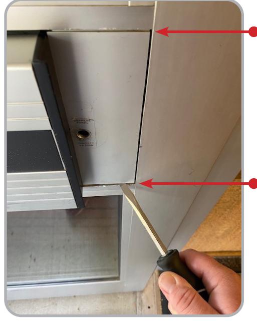
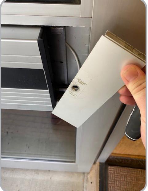
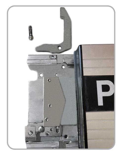
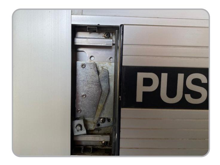
1 Using a flat screw driver or putty knife, gently pry at top and bottom on Filler Plater on each side of device until they come out
2 Once exposed remove (4) Philips head mounting screws and remove push pad from pocket in door
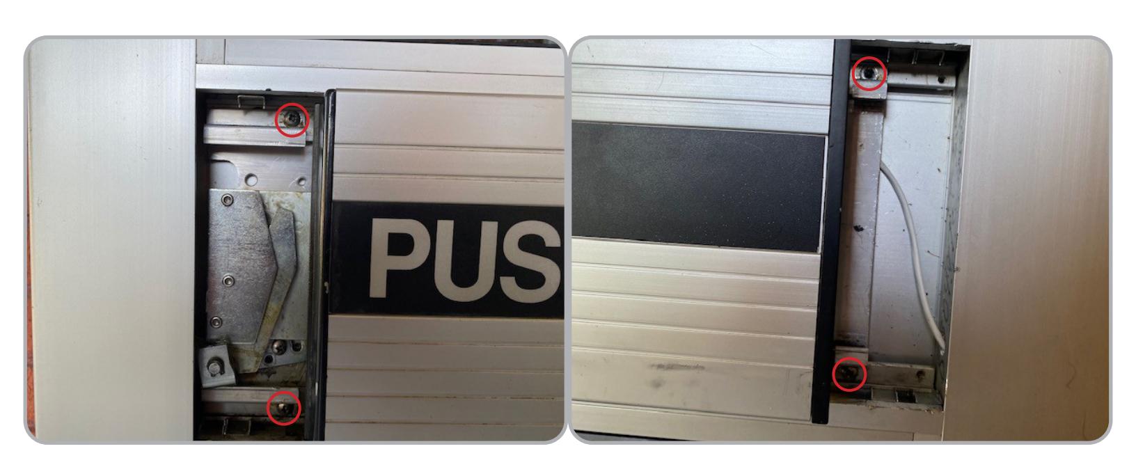

3 Remove (4) Philips head screws attaching Push Pad to chassis

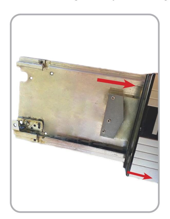
5 Remove Push Pad from chassis by pulling in opposite directions, if it proves difficult to separate, a rubber mallot can be used to get it past any stubborn points.
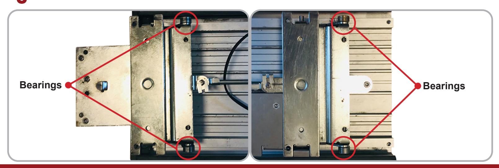
Watch for bearings that may fall out during removal.
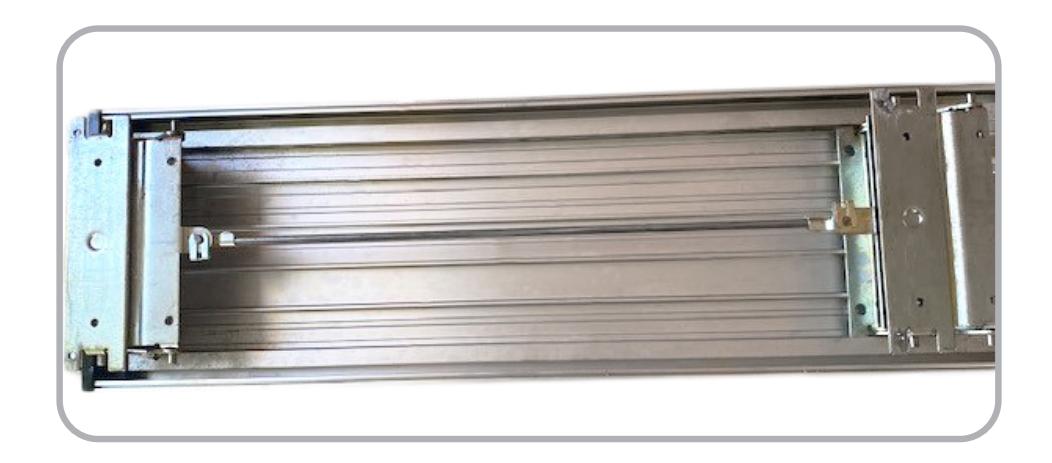
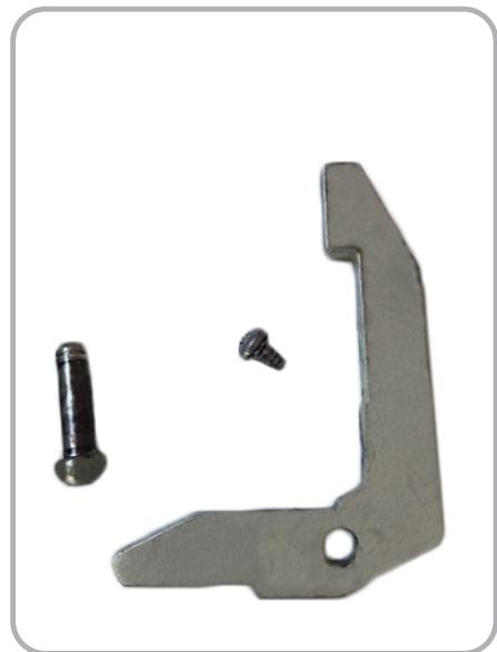
1 With the Push Pad removed, flip it over and locate the Rear Activating Bracket .
2 Locate the Opening in the Rear Activating Bracket , this is where the kits head link will slide through.
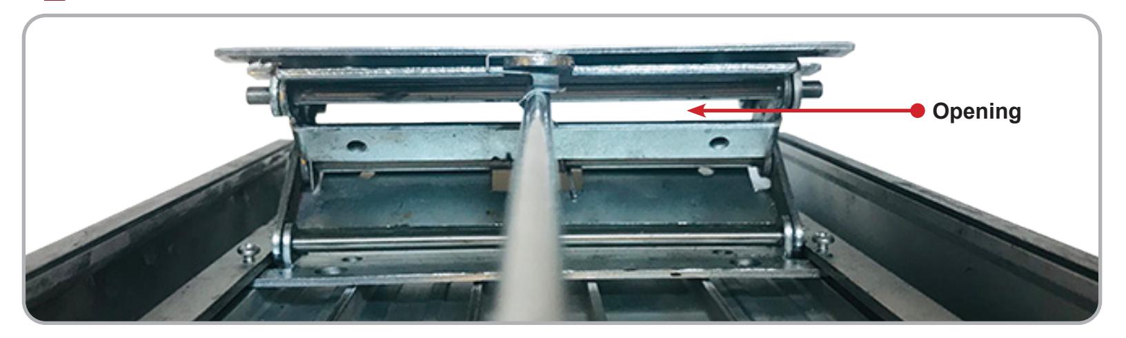
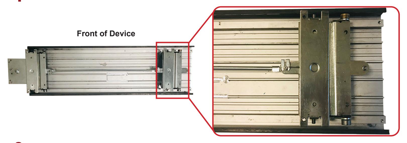
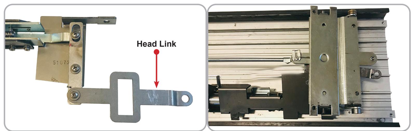
3 Flip the Motor Kit over so the underside is facing you, next slide the Head Link of the motor kit through the Rear Activating Bracket Opening .

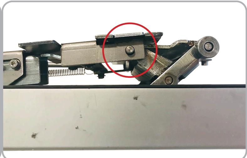
4 Fit the Hole on the end of the Head Link over the Rear Post of the Rear Mounting Bracket as shown.
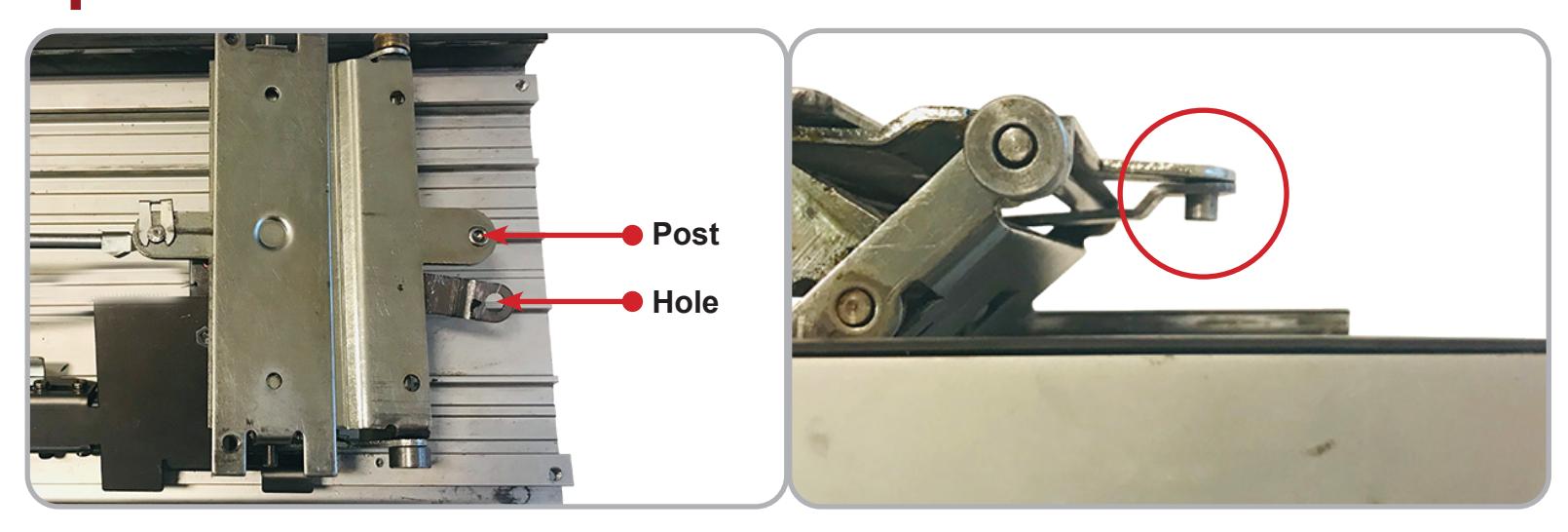
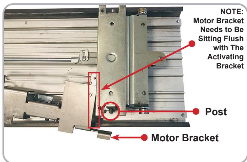
5 Then fit the Hole on the Motor Bracket over the Side Post of the Rear Mounting Bracket as shown.
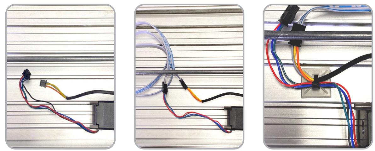
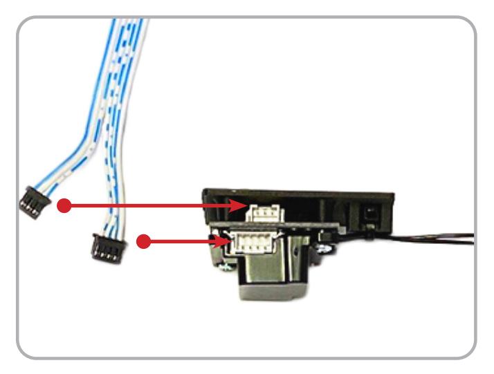
Once kit is in place connect 3-Pin and 4 -Pin Connectors on the Remote Module Cable to 3-pin and 4-Pin Connectors from Motor and Sensor . Apply Strain Relief as shown below or to installers best 6 judgement.
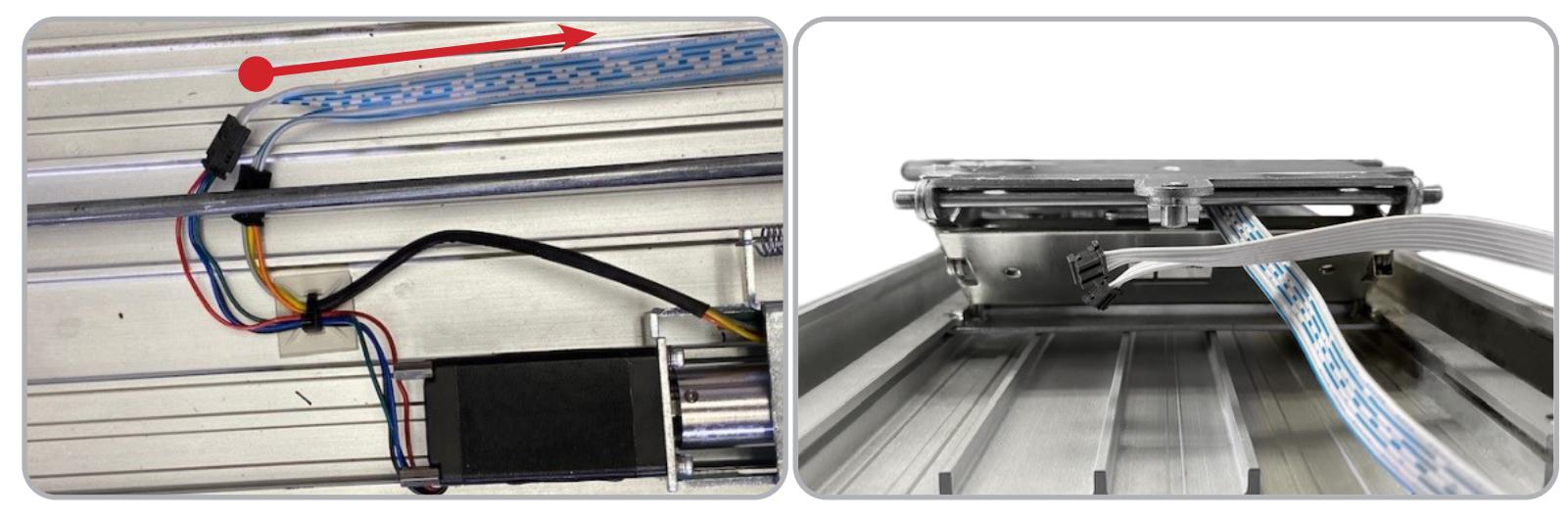
7 Guide wire to rear of device and feed through Back Activating Bracket . Ensure nothing is being pinched or strained by depressing the Back Activating Bracket .
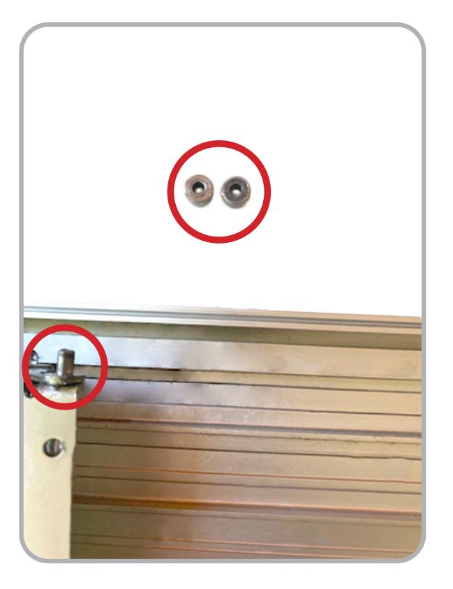
8 Before re-installing the Push Pad , ensure the bearings are still on the Activating Brackets !
INSTALLATION INSTRUCTIONS

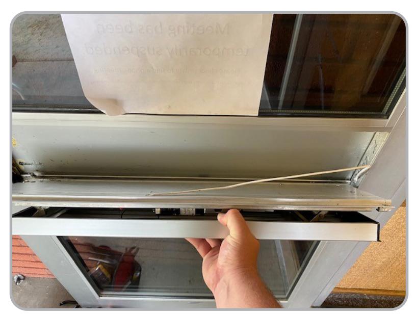
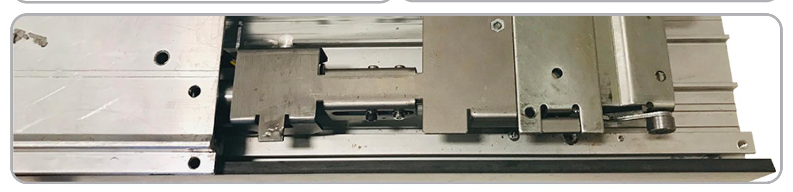
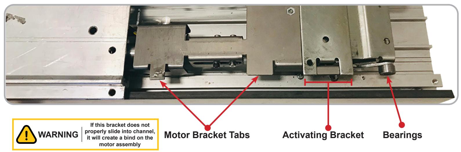
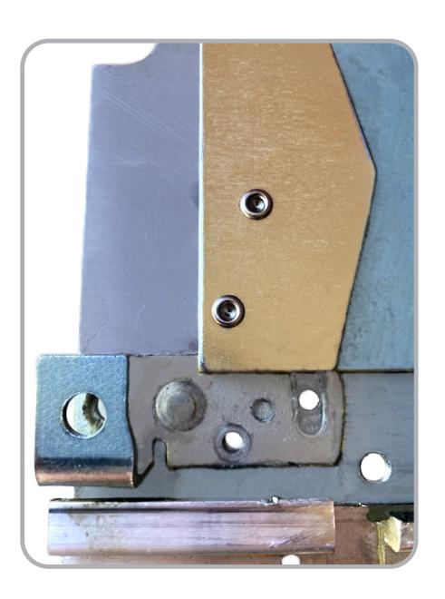
Re-install the Base Rail, making sure the Front Activating Bracket and Bearings slide into their Slots.
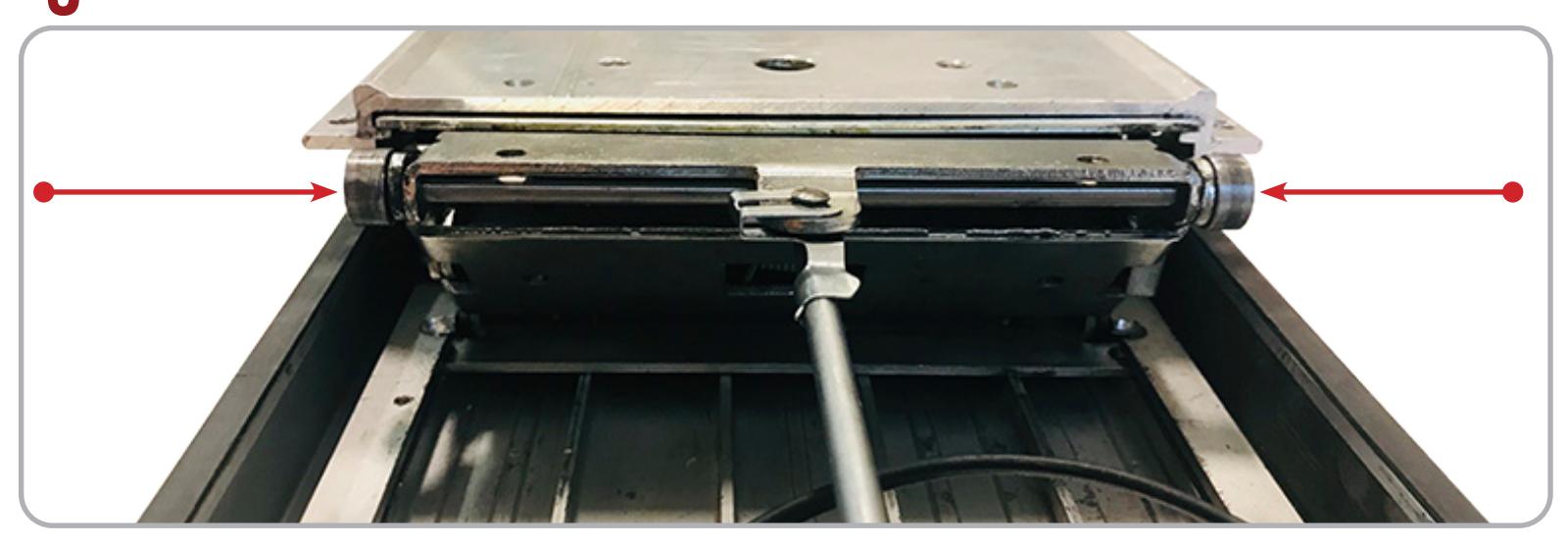
The Two Tabs on the Motor Bracket , Rear Activating Bracket and Bearings must also slide into the Slots on the Base Rail .
#20638_D
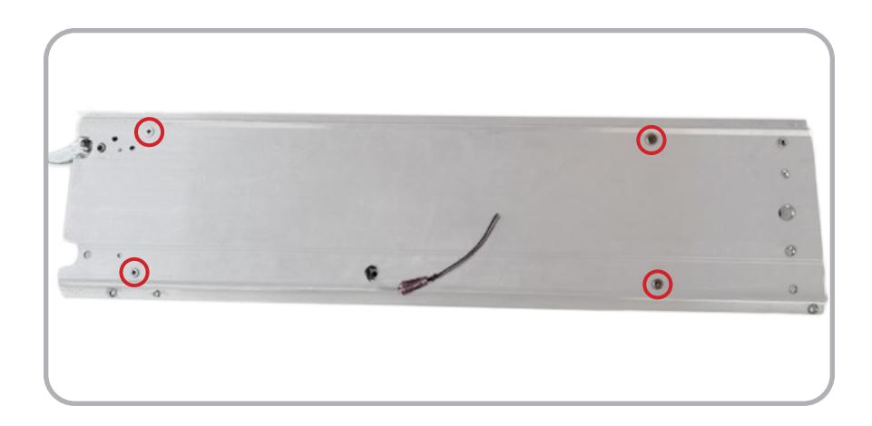
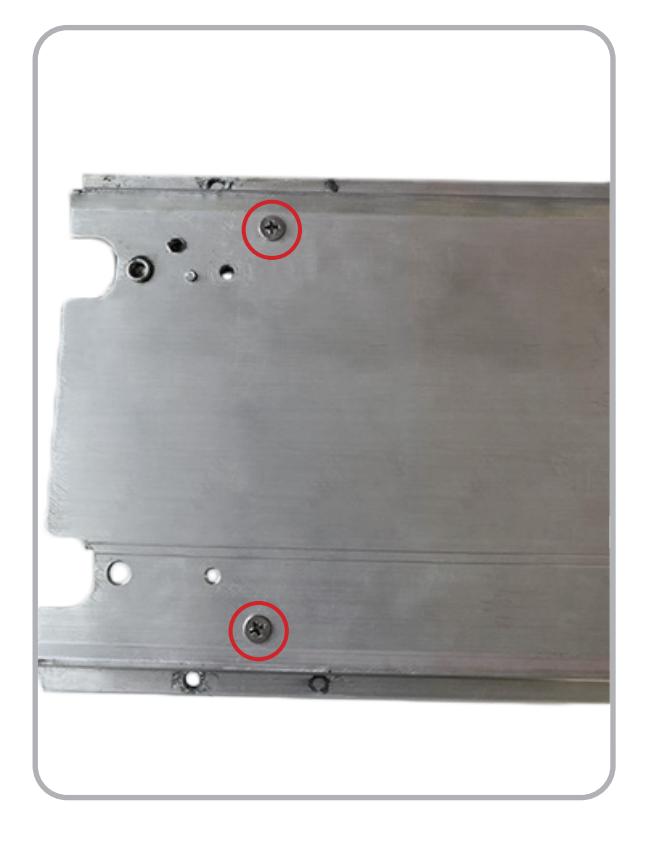
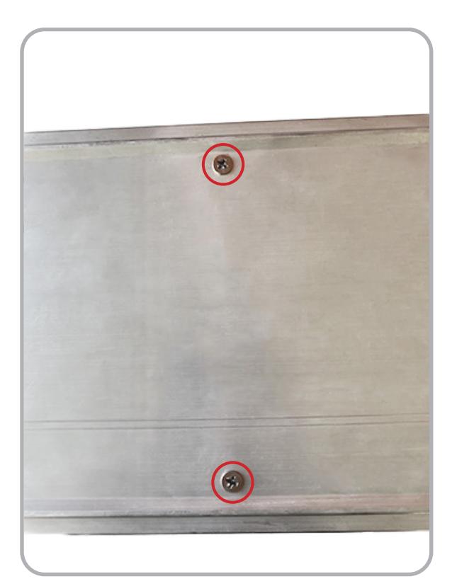
11 Re-secure the Baserail & re-mount the items that were removed in Step 4.
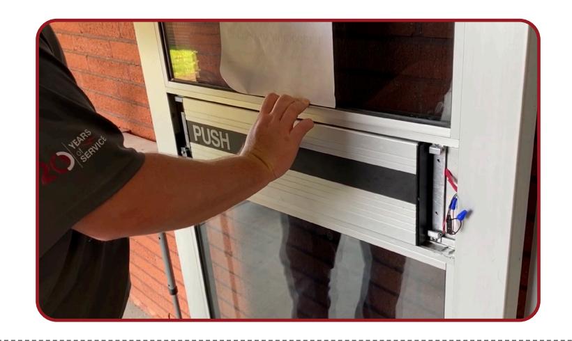
12 Re-install Device back into the door.
INSTALLATION INSTRUCTIONS

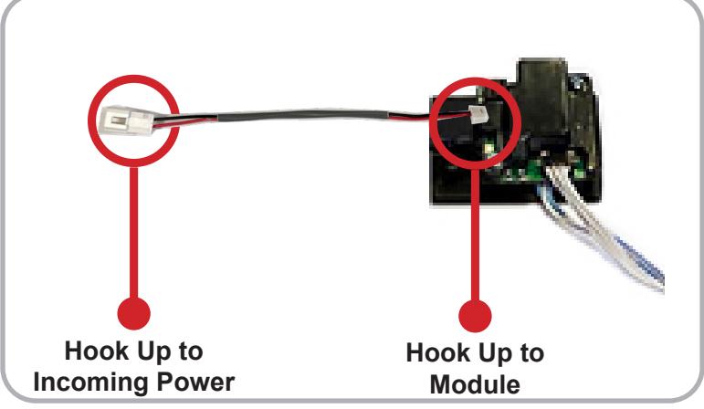
Connect 3-Pin and 4-Pin Connectors from RM Cable to Remote MM4 Module , mount Module in empty pocket using double sided tape. Hook incoming power to 2-Pin Connector using provided power lead.
#20638_D
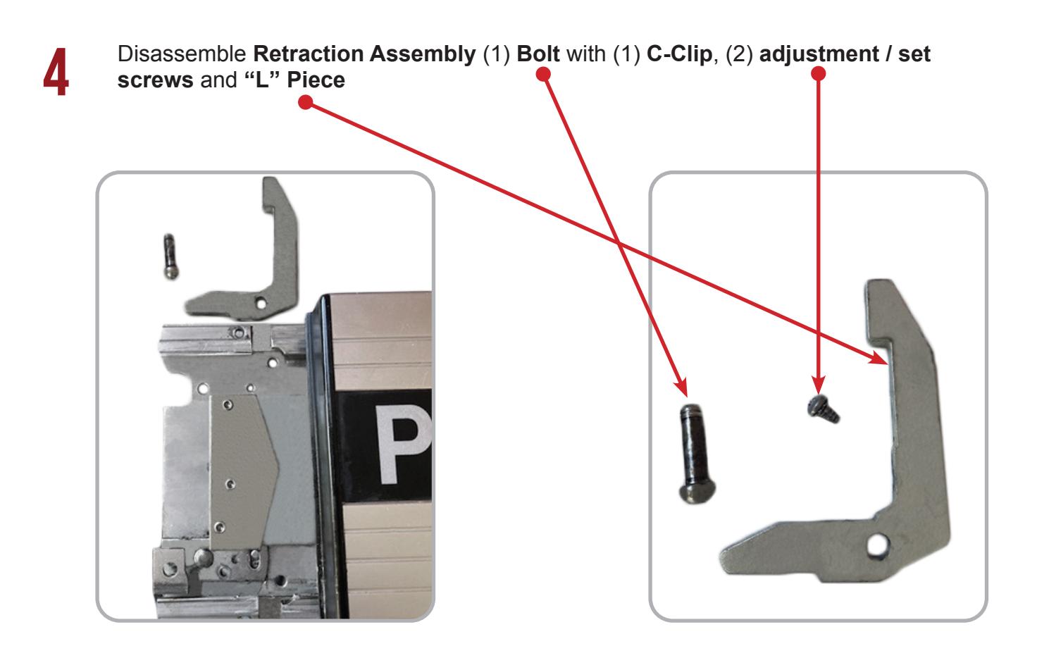
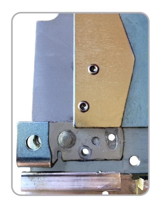
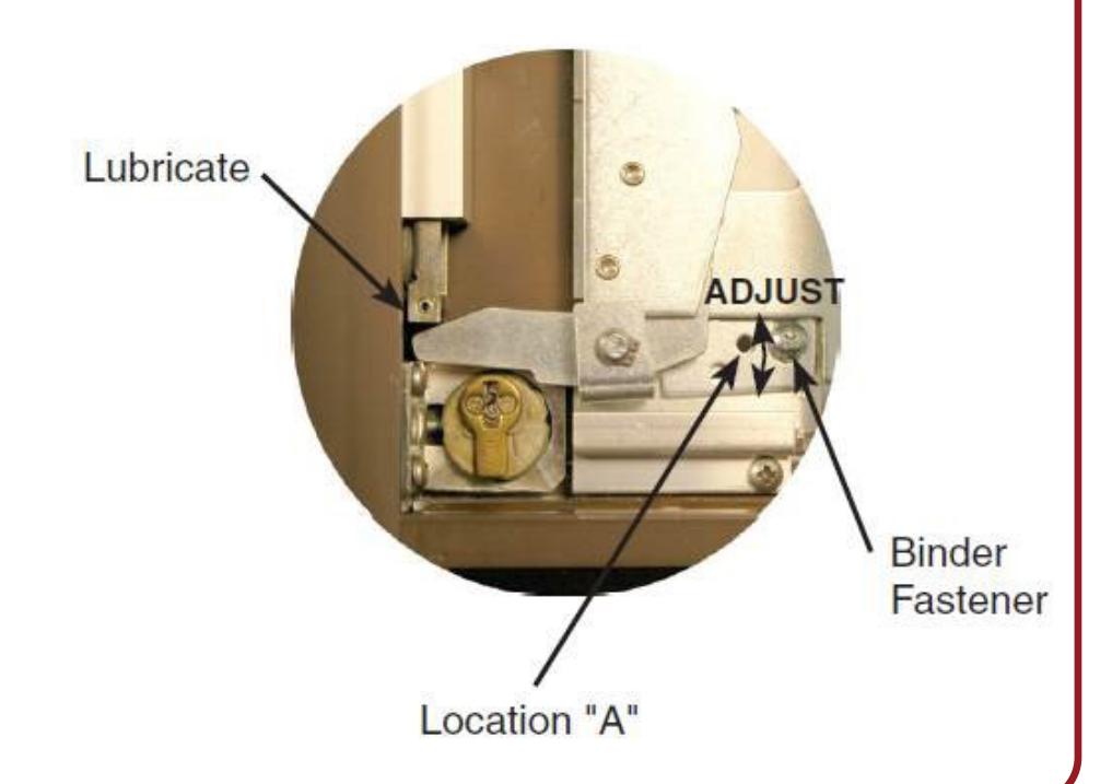
14 If mechanical adjustment of Retaction Arm is needed please follow instructions below
PUSH TO SET (PTS)

15
Setting PUSH TO SET (PTS)
**Important Info**
Make sure to set PTS before finishing installation
- Step 1 - Select your preferred torque mode (ships in standard torque). Press the device push pad to the desired setting. (We recommend to fully depress and release 5%, giving the device room for changing door conditions.)
- Step 2 - While depressing the push pad, apply power.
- Step 3 - Continue to keep the pad depressed, the device will beep 6 times. After the beeps have stopped, release the pad and the adjustment is now set. Test the adjustment 4 to 5 times and if not to your liking repeat the above steps.
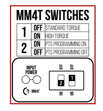
*Once you found your preferred adjustment, we recommend turning off the PTS programming switch.
Troubleshooting & Diagnostics
| Beeps | Explanation | Solution |
|---|---|---|
| 2 Beeps | Over Voltage | > 30V unit will shut down. Check voltage & adjust to 24 V. |
| 3 Beeps | Under Voltage | < 20V unit will shut down. Check voltage & adjust to 24 V. |
| 4 Beeps | Failed Sensor |
Verify all 3 sensor wires are installed correctly. Replace sensor if problem
persists by contacting office. |
| 5 Beeps | Retraction or dogging failure |
After 1st fail: 5 beeps then immediately attempts to retract again.
After 2nd fail: 5 beeps with pause in-between for 30 seconds then device attempts to retract again. After 3rd fail: 5 beeps every 7 minutes, device will not attempt to retract. To Reset: Depress bar for 5 seconds at any time. |
| 6 Beeps | PUSH TO SET | Device is recording it's new position and power mode after the 6th beep. |
*TRIM POT ADJUSTMENT ONLY REQUIRED WHEN PTS PROGRAMMING IS NOT SETTING TO THE CORRECT LOCATION

*Latch bolt adjustment- If the latch bolt is not retracting far enough, turn the dial clockwise with a small flat blade screw driver. If the latch bolt is retracting too far causing the device to chatter and drop-out, turn the dial counter-clockwise until the chatter and drop-outs stop and the desired location is achieved.
#20638_D