MLRK1-JAC12 Insert Instructions
Open the original PDF document
View PDF


MLRK1
I N S E R T I n s t r u c t i o n s
The Command Access MLRK1 is a field-installable motorized latch-retraction kit for:
- MLRK1-JAC 12 Jackson 1285, 1286 and 1295 series devices
- MLRK1-KAW17 Kawneer 1686 and 1786 series devices
- MLRK1-AHT AHT 8 and 9 series devices
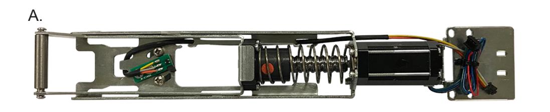

- A. 60241 MLRK1 motor
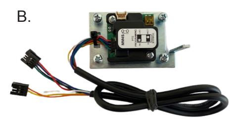
- B. 60372– mm4 module
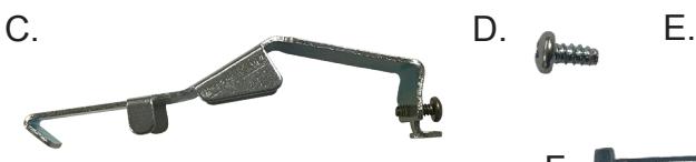
- C. 50453 magnet bracket
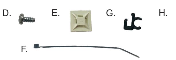
- D. 40040 phillips Screws (x2)
- E. 40059 cable mounting pad
- F. 40060 cable tie (x2)
- G. 50636 Cable guides (x3)
- H. 50944 Molex Pigtail
- I. 6' Power Lead w/ vd connector
Kit Includes Tools Required
- cordless drill
- 1/16" Drill bit
- minor cutting tools and file
- #0 phillips screwdriver
- #2 phillips screwdriver
SPECIFICATIONS
- Input Voltage: 24VDC +/- 10%
- Standard Torque AVERAGE LATCH RETRACTION CURRENT: 1.3A
- High torque average latch retraction current: 2a
- Average holding current: 215 ma
- Wire gauge: Minimum 18 gauge
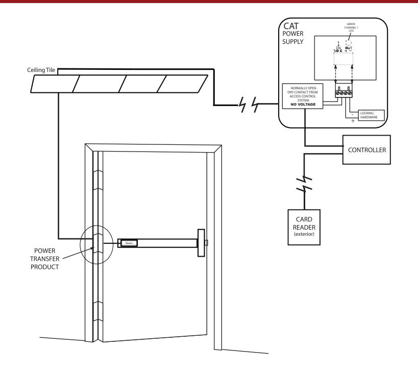
- Direct wire run no relays or access control units in-between power supply & module
Recommended Power Supplies:
All Command Access exit devices & field installable kits have been thoroughly cycle tested with Command Access power supplies at our factory. If you plan on using a non-Command power supply it must be a filtered & regulated linear power supply.
Optional built-in rex
- SPDT Rated .5a @24V
- green= Common (C)
- Blue = normally open (NO)
- grey = normally closed (NC)
#20379_M
TECHNICAL INFORMATION


SETTING PTS **IMPORTANT INFO**
MAKE SURE TO SET PTS BEFORE FINISHING INSTALLATION
- STEP 1 - Select your preferred torque mode (ships in standard torque). Press the device push pad to the desired setting. (We recommend to fully depress and release 5%, giving the device room for changing door conditions.)
- STEP 2 While depressing the push pad, apply power. (i.e. presenting the credential to the reader).
- STEP 3 Continue to keep the pad depressed, the device will beep 6 times. After the beeps have stopped, release the pad and the adjustment is now complete. If not to your liking repeat the 3 steps.
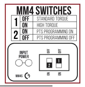
| MM4 SWITCHES | ||
|---|---|---|
| d OFF | STANDARD TORQUE | |
| ON | HIGH TORQUE | |
| 9 0N | PTS PROGRAMMING ON | |
| ∠ OFF | PTS PROGRAMMING OFF | |
| INPUT POWER | NO NO PER PER PER PER PER PER PER PER PER PER | |
TROUBLESHOOTING & DIAGNOSTICS
| BEEPS | EXPLANATION | SOLUTION |
|---|---|---|
| 2 Beeps | Over Voltage | > 30V unit will shut down. Check voltage & adjust to 24 V. |
| 3 Beeps | Under Voltage | < 20V unit will shut down. Check voltage & adjust to 24 V. |
| 4 Beeps | Failed Sensor | Verify all 3 sensor wires are installed correctly. Replace sensor if problem persists by contacting office. |
| 5 Beeps | Retraction or dogging failure | After 1st fail: 5 beeps then immediately attempts to retract again. After 2nd fail: 5 beeps with pause in-between for 30 seconds then device attempts to retract again. After 3rd fail: 5 beeps every 7 minutes, device will not attempt to retract. To Reset: Depress bar for 5 seconds at any time. |
| 6 Beeps | PUSH TO SET | Device is recording it's new position and power mode after the 6th beep. |
installation instructions

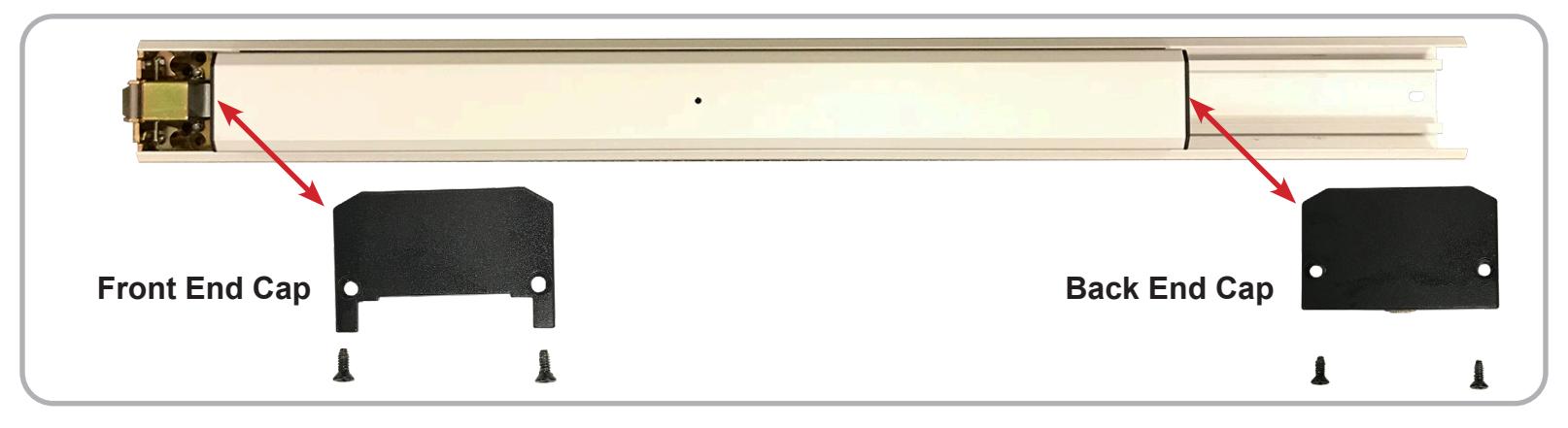
1 Remove the Front and Back End Caps , which are held on by four screws (two each).
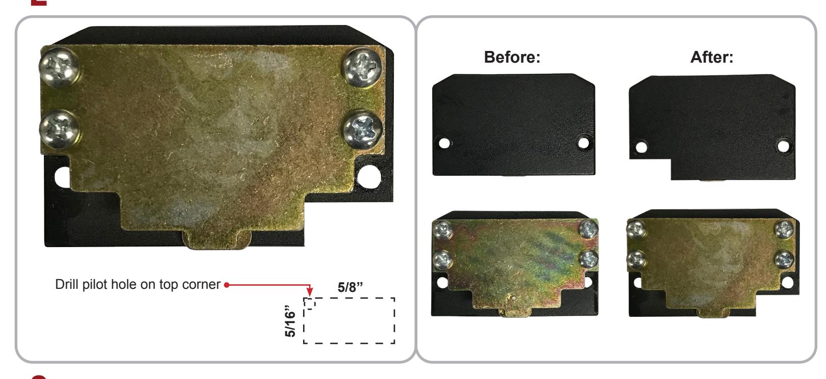
2 Material will need to be removed from the Back End Cap .
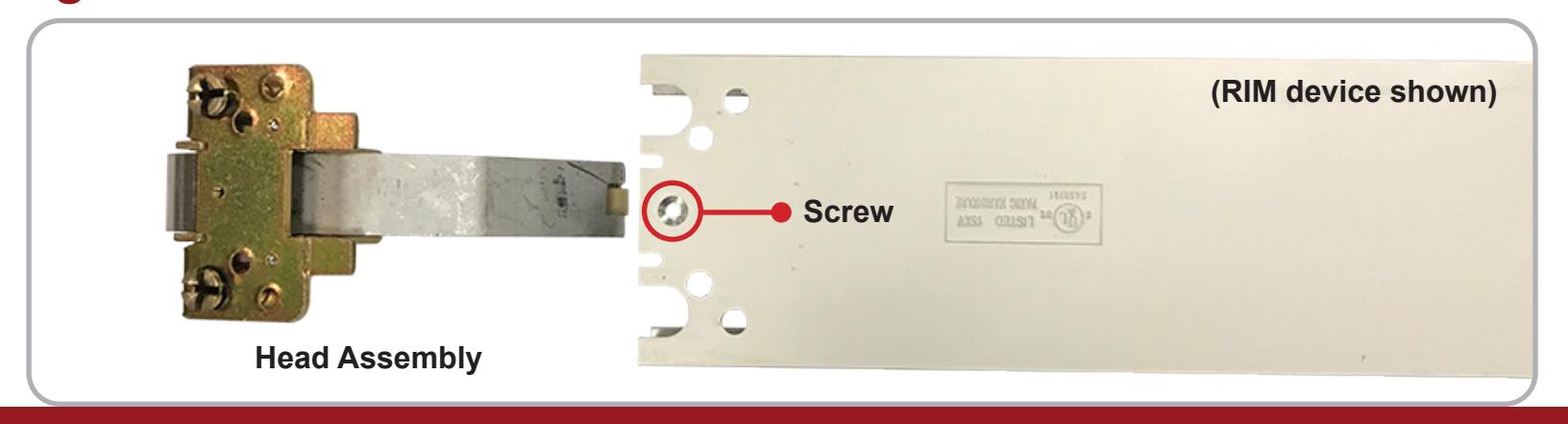
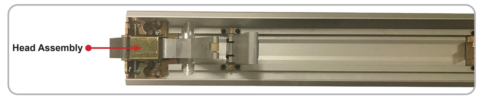
3 Flip the bar over to remove Head Assembly . RIM devices will be held in by 1 screw, CVR devices by 2.

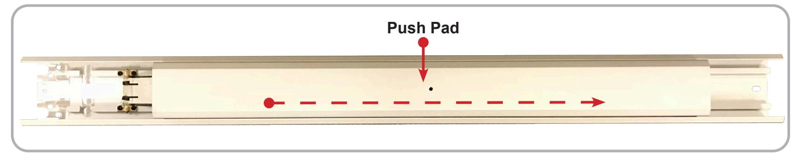
Flip the device back over and slide the Push Pad to the right, exposing the Front Activating Bracket . *Move the Push Pad slowly as some Front Activating Bracket pieces are held in by the Push Pad and tend to fall out when exposed.
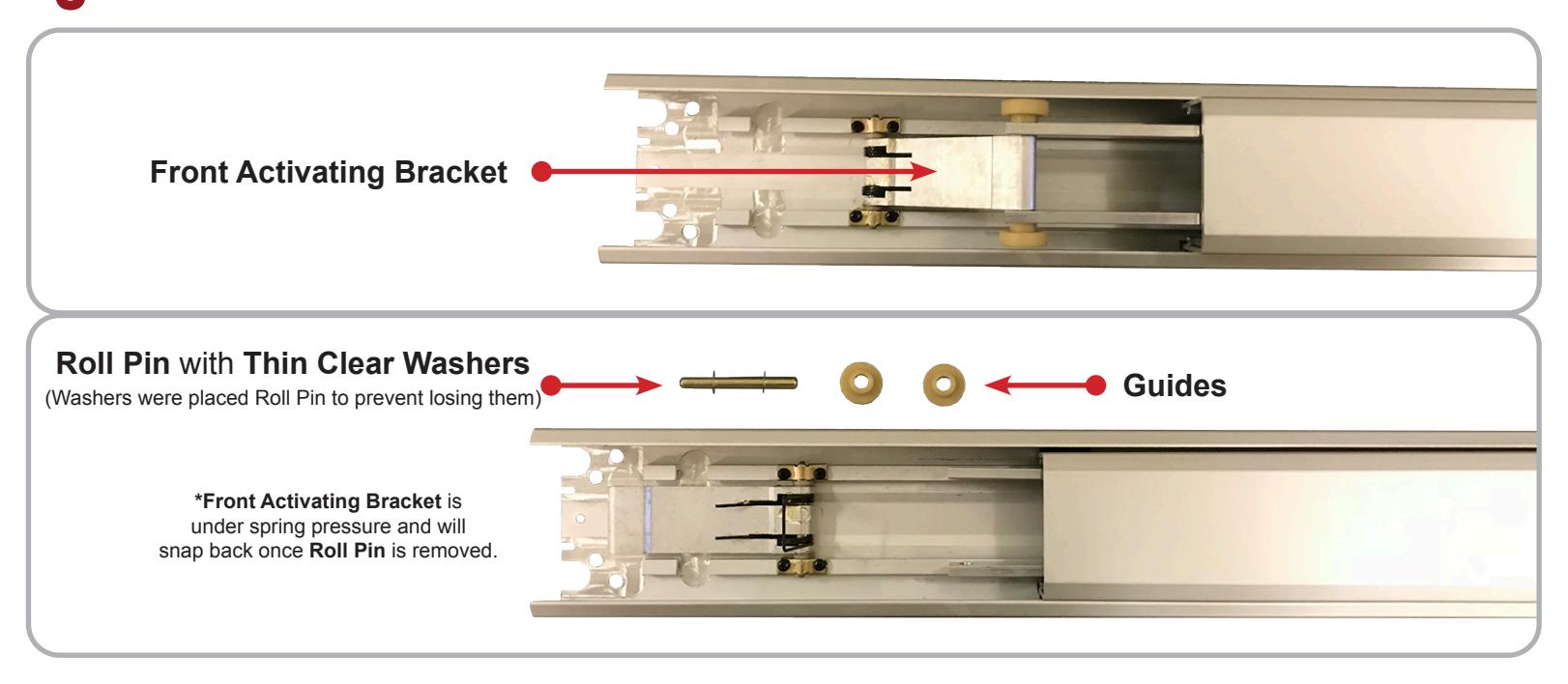
With the Front Activating Bracket exposed, remove the Guides, Thin Clear Washers and Roll Pin.
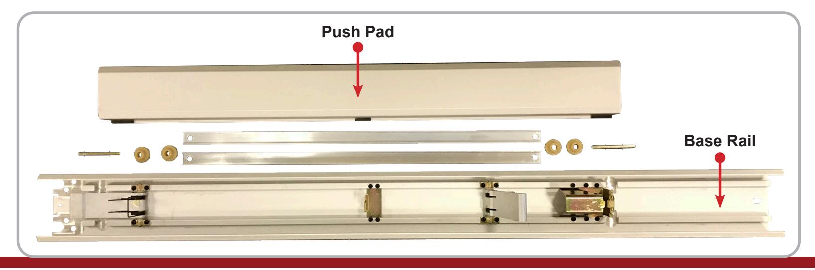
Slide the Push Pad to the left to expose the Back Activating Bracket and remove its pieces as well. Once removed, continue sliding the Push Pad to the left and remove it from the Base Rail .
installation instructions

7 Reinstall the Head Assembly .
Flip the Push Pad over and remove the Dogging Assembly underneath (four screws). 8

9 Install the Magnet Bracket by first hooking the bottom tab under the Front Activating Bracket . Then press on the top plane to snap the Magnet Bracket in place.
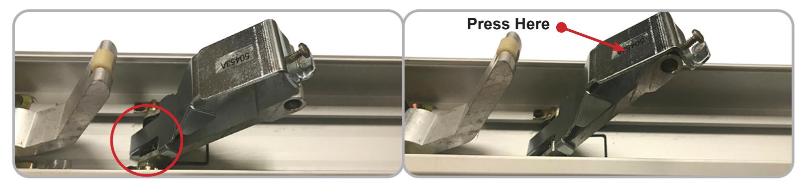
10 Once snapped in place, tighten the Top Screw to secure the Bracket in position.


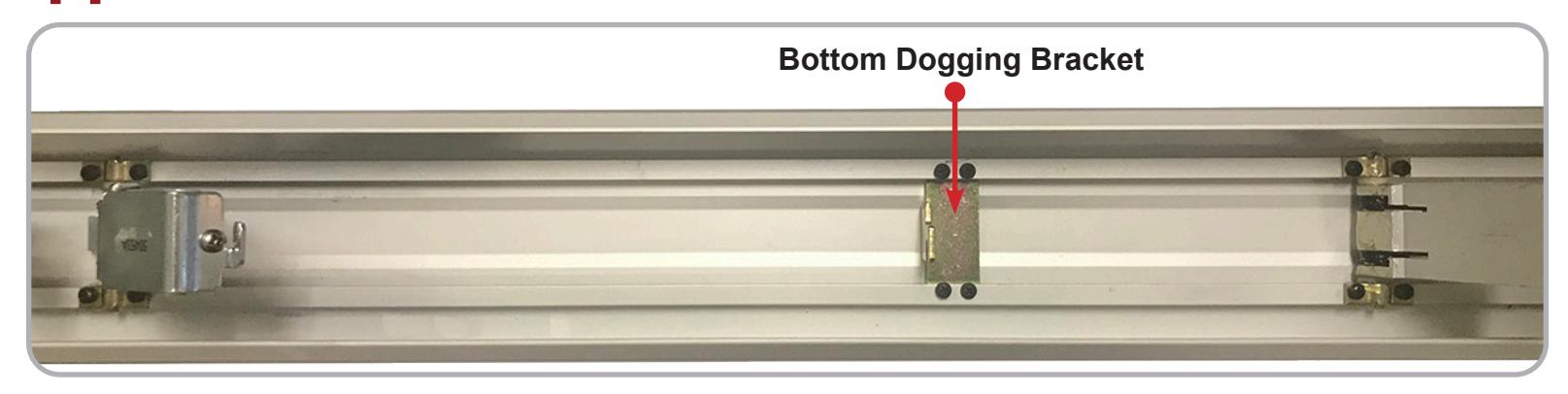
Remove the four screws from the Bottom Dogging Bracket , keep the Bracket in place.
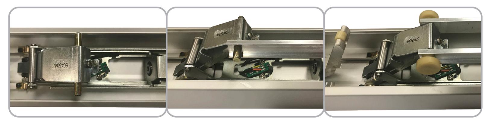
Flip MLRK1 over and angle the Scissor Bracket to match the position shown below.
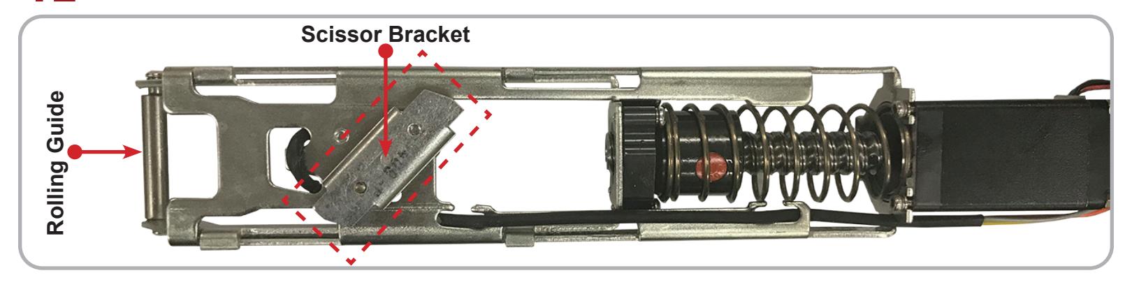
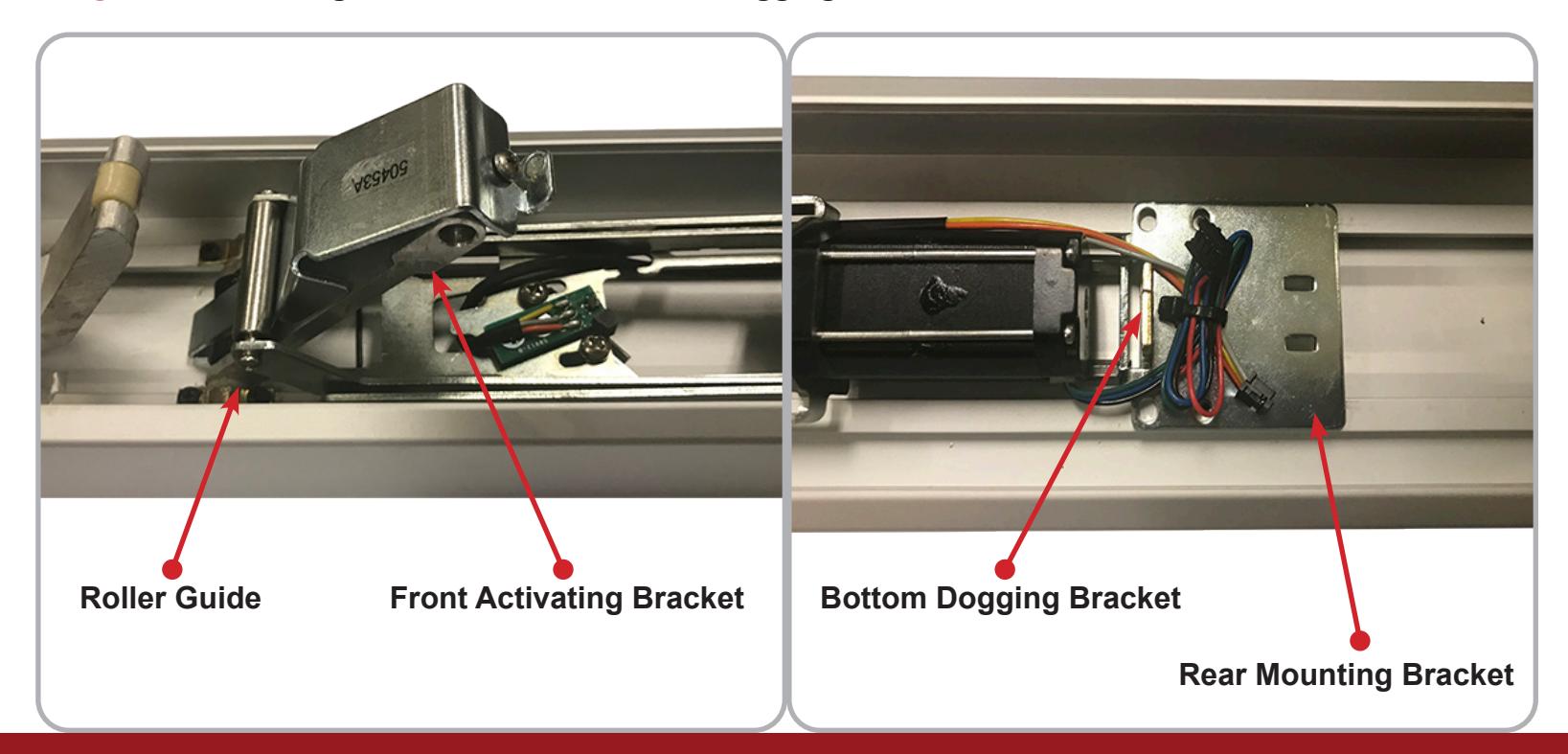
To install the MLRK1, slide the Rolling Guide over the Front Activating Bracket . Then place the Rear Mounting Bracket over the Bottom Dogging Bracket as shown below.
installation instructions

14
If you are installing the MLRK1 into a Jackson series device:
• Use the Front screw hole locations on the Rear Mounting Bracket and align with the front holes on the Base Rail.
If you are installing the MLRK1 into a Kawneer or AHT series device:
• Use the Back screw hole locations on the Rear Mounting Bracket and align with the back holes on the Base Rail.
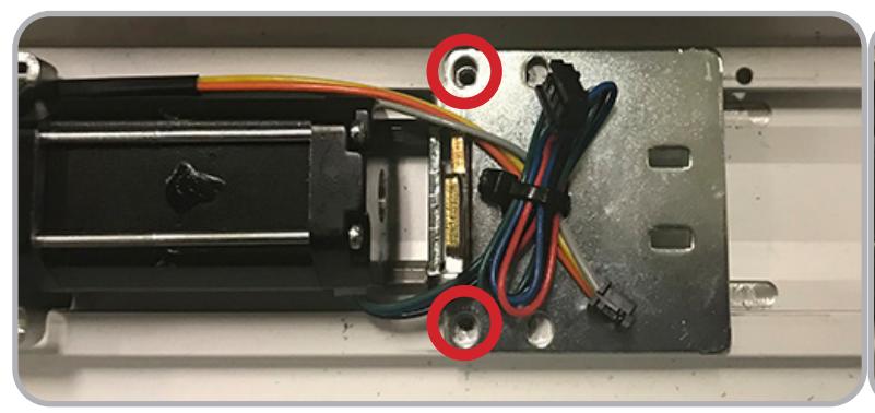
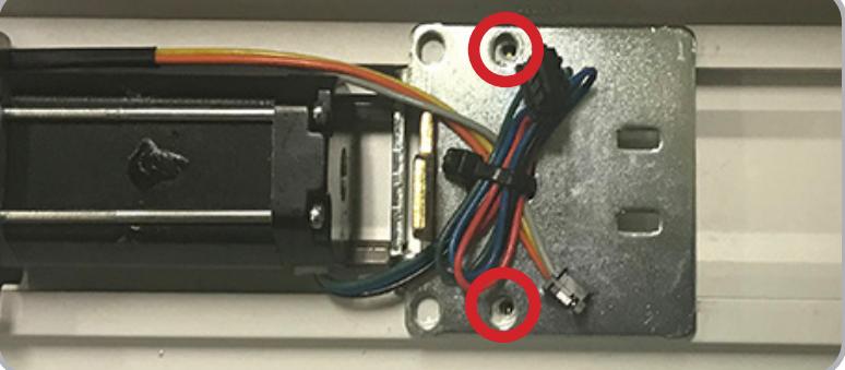
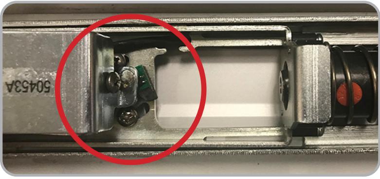
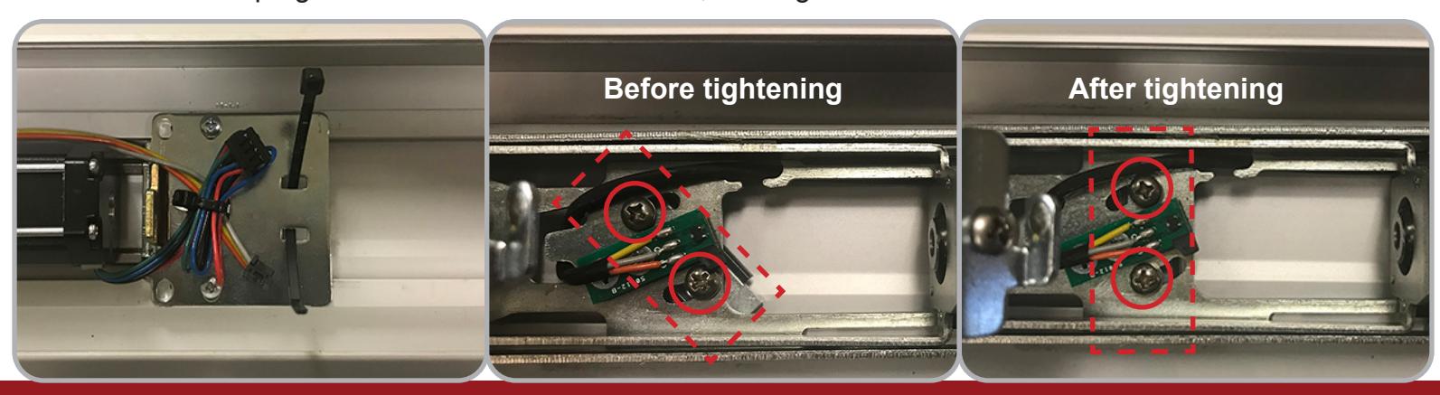
To verify you have used the correct hole locations, temporarily install the two provided screws into the Rear Mounting Bracket . Then press down the Front Activating Bracket and comprae how it lines up with the Green Sensor Board to the pictures shown below.
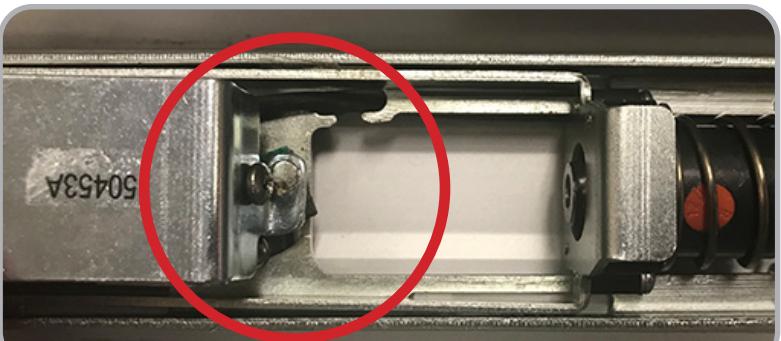
CORRECT INCORRECT
After verifying the correct screw hole location, add the provided Cable Tie to the Rear Mounting Bracket as shown and tighten the back two screws. 15
Then ensure the Screws holding down the Scissor Bracket are still angled correctly and the MLRK1 is sitting flush against the Base Rail . Once the MLRK1 is in place, rotate the Scissor Bracket until its Screws stop against the cut outouts as shown, then tighten the Screws .

Next, slide the Module Bracket into the Channel at the bottom of the Base Rail .
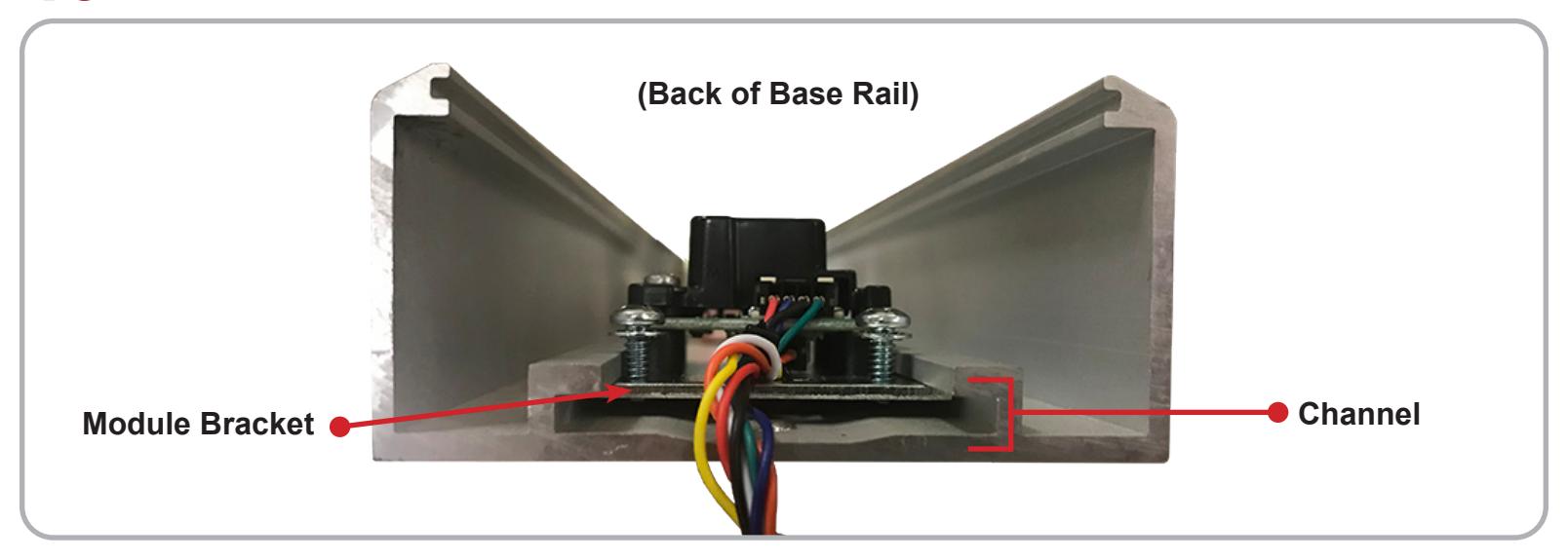
The up the edge of the Module Bracket to the machining mark on the Base Rail , then tighten all four screws. (The Module Harness should be running out the back of the Base Rail )
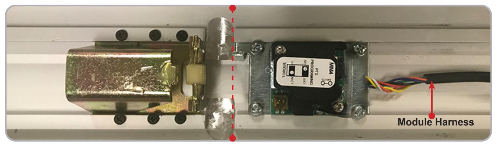
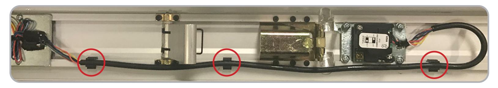
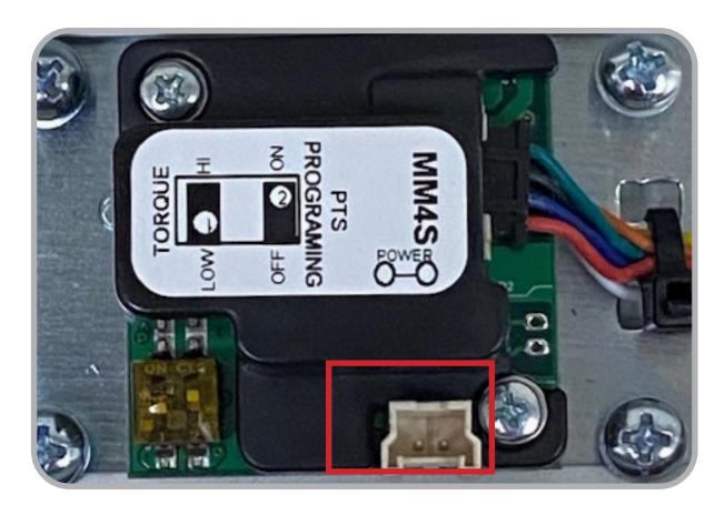
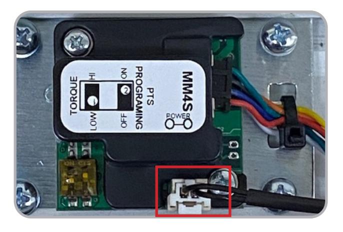
Plug the other end of the Module Wiring Harness into the the MLRK1 and secure it with the Zip Tie . You will use the three provided Cable Guides to finish installing the Module Wiring Harness , which will be installed on the Channel as shown below.
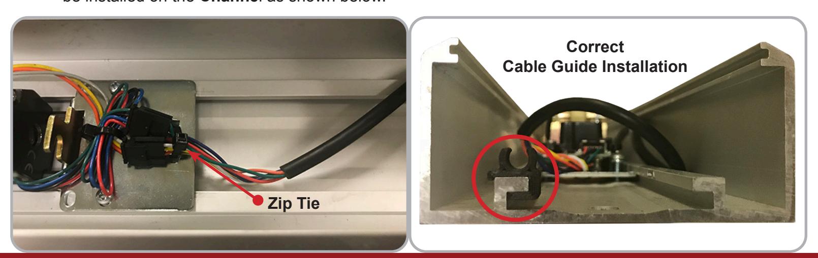

Install the Cable Guides as shown, then press the Module Wiring Harness into them.
-
Reassmble the
Front
and
Back Activating Brackets
by:
- First sliding the Rolls Pins into the brackets
- Then placing the two Connecting Rods on the Roll Pins as shown
- Finally slide on the Thin Clear Washers and Guides to complete the assembly
Reinstall the Push Pad , making sure the Activating Bracket Guides sit in their correct channel. Then install the Front End Cap and its two screws.
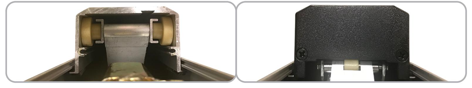
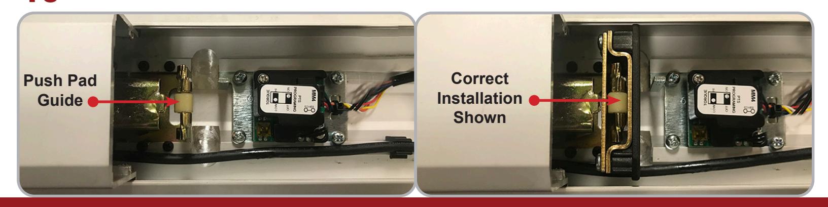
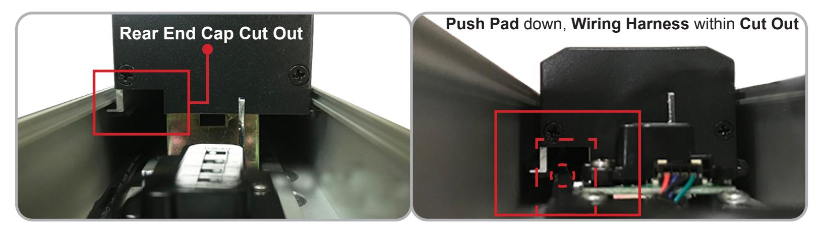
1 | *IMPORTANT* When reinstalling the Rear End Cap, make sure that it is riding on the Push Pad Guide.

*IMPORTANT* After reinstalling the Rear End Cap and its two screws, double check to make sure the Module Wiring Harness is in the Cut Out and not being hit by the Rear End Cap.
Install Molex Pigtail & hook up to power. Set the "Push to Set Adjustment" following the steps below, remembering to turn the Programming Switch to the off position when completed.
MAKE SURE TO SET PTS BEFORE FINISHING INSTALLATION
- STFP 1 - Select your preferred torque mode (ships in standard torque). Press the device push pad to the desired setting. (We recommend to fully depress and release 5%, giving the device room for changing door conditions.)
- STEP 2 While depressing the push pad, apply power. (i.e. presenting the credential to the reader).
- STEP 3 Continue to keep the pad depressed, the device will beep 6 times. After the beeps have stopped, release the pad and the adjustment is now complete. If not to your liking repeat the 3 steps.
SPECIFICATIONS FOR OPTIONAL REX:
- Single Pole Double Throw (SPDT)
- Rating: 0.5A @24VAC
- Configuration: Green Common (C)
Blue - Normally Open (NO) Gray - Normally Closed (NC)