MLRK1-HAG Insert Instructions
Open the original PDF document
View PDF


mlrk1-
INSERT INSTRUCTIONS
The Command Access MLRK1 is a field installable motorized latch-retraction kit for:
- MRLK1-HAG Hager 45/4600 series devices
- MRLK1-IDC IDC 8000 series devices
- MRLK1-PDQ PDQ 6200 series devices
- MRLK1-SQ Stanley QED 1/2000 series devices
- MRLK1-LAW Lawrence 8000 series devices
- MRLK1-LSDA1 LSDA 9000 R/V series devices
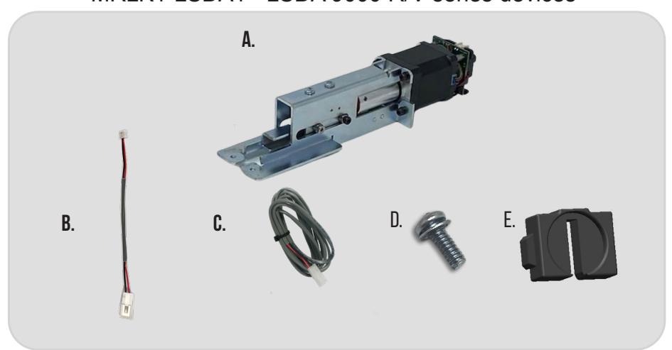
A.
1- 50944 - Molex Pigtail B.
1- 50030 - 6' Lead w/ VD Connector C.
2- 40320 - M4 x 6MM Phillips Screws D.
1- 51235 Spacer E.
Kit Includes Tools Required
1- Motor Mount w/MM5 - Cordless Drill or Phillips Screwdriver
SPECIFICATIONS
- Input Voltage: 24VDC +/- 10%
- AVERAGE LATCH RETRACTION CURRENT: 900 mA
- Average holding current: 215 ma
- Wire gauge: Minimum 18 gauge
- Direct wire run no relays or access control units in-between power supply & module
Recommended Power Supplies: Use a power limited class 2 power supply
All Command Access exit devices & field installable kits have been thoroughly cycle tested with Command Access power supplies at our factory. If you plan on using a non-Command power supply it must be a filtered & regulated linear power supply.
Optional built-in rex
- SPDT Rated .5a @24V
- green= Common (C)
- Blue = normally open (NO)
- grey = normally closed (NC)
TECHNICAL INFORMATION


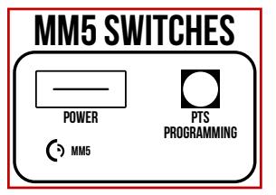
SETTING PUSH TO SET (PTS)

MAKE SURE TO SET PTS BEFORE FINISHING INSTALLATION
- STEP 1 - To enter PTS mode: Depress MM5 button & apply power. The device will emit 1 SHORT beep. The device is now in PTS mode.
- STEP 2 - While depressing the push pad, apply power. (i.e. presenting the credential to the reader).
- STEP 3 Continue to keep pad depressed, the device will emit 1 LONG Beep. After the beep has stopped, release the pad and now the adjustment is complete. test the new location, If not to your liking repeat the 3 steps.
TROUBLESHOOTING & DIAGNOSTICS
| BEEPS | EXPLANATION | SOLUTION |
|---|---|---|
| 2 Beeps | Over Voltage | > 30V unit will shut down. Check voltage & adjust to 24 V. |
| 3 Beeps | Under Voltage | < 20V unit will shut down. Check voltage & adjust to 24 V. |
| 4 Beeps | Failed Sensor | Verify all 3 sensor wires are installed correctly. Replace sensor if problem persists by contacting office. |
| 5 Beeps | Retraction or dogging failure | After 1st fail: 5 beeps then immediately attempts to retract again. After 2nd fail: 5 beeps with pause in-between for 30 seconds then device attempts to retract again. After 3rd fail: 5 beeps every 7 minutes, device will not attempt to retract. To Reset: Depress bar for 5 seconds at any time. |
INSTALLATION INSTRUCTIONS

1 Remove Head Cover from device.
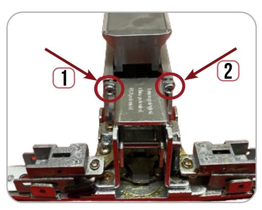
2. Remove (2) Screws securing Housing to Baserail.
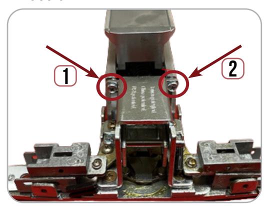
3. Slide off Housing to expose Pushpad & Baserail Assembly.
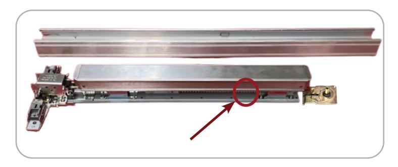
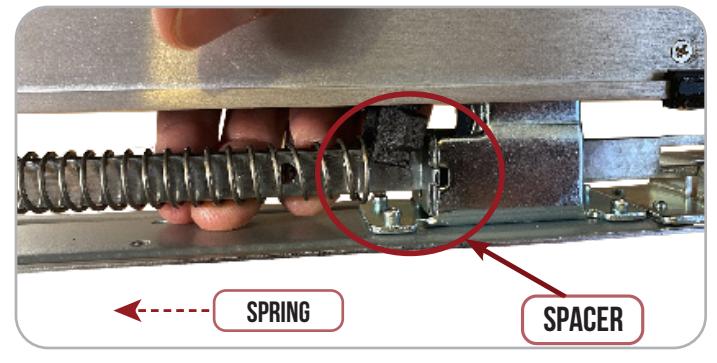
Install Spacer onto connecting rod in front of the back activating bracket to increase the return spring tension. Make sure Spacer is facing the correct direction.
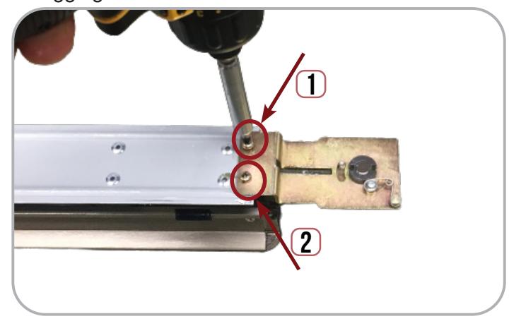
5. If your device has Mechanical Dogging , flip Baserail over & remove (2) screws securing dogging to Baserail.
6. Push Down on Push Pad to extend connecting Rod's Dogging Hole.
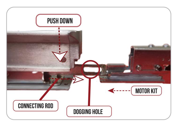

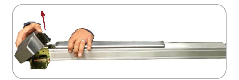
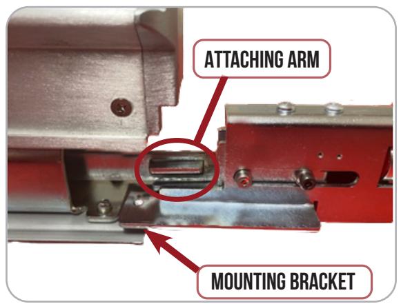
7. Slide Motor Kit's Attaching Arm into Dogging Hole. Make Sure the motor kit mounting bracket is on TOP of Baserail.
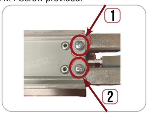
8. Flip Baserail/Pushpad over, holding motor kit in place so it stays attached. Secure Motor Kit with (2) M4 Screw provided.
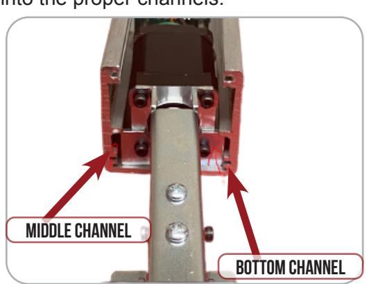
9. Slide Baserail motor side 1st back into the exit device Housing. Make sure the Motor & baserail go into the proper channels.
10. Re-install (2) Screws securing Housing to Baserail.
11. Set the "Push to Set Adjustment" following the steps below.

SETTING PUSH TO SET (PTS)
→ **IMPORTANT INFO** ← MAKE SURE TO SET PTS BEFORE FINISHING INSTALLATION
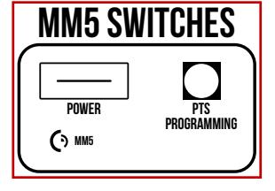
- STEP 1 - To enter PTS mode: Depress MM5 button & apply power. The device will emit 1 SHORT beep. The device is now in PTS mode.
- STEP 2 While depressing the push pad, apply power. (i.e. presenting the credential to the reader).
- STEP 3 - Continue to keep pad depressed, the device will emit 1 LONG Beep. After the beep has stopped, release the pad and now the adjustment is complete, test the new location, If not to your liking repeat the 3 steps.