MLRK1-FAL25-Insert-Instructions
Open the original PDF document
View PDF


MLRK1-FAL25
I N S E R T I n s t r u c t i o n s
The Command Access MLRK1 is a field-installable motorized latch-retraction kit for: MLRK1-FAL25 - Falcon 24 & 25 series devices
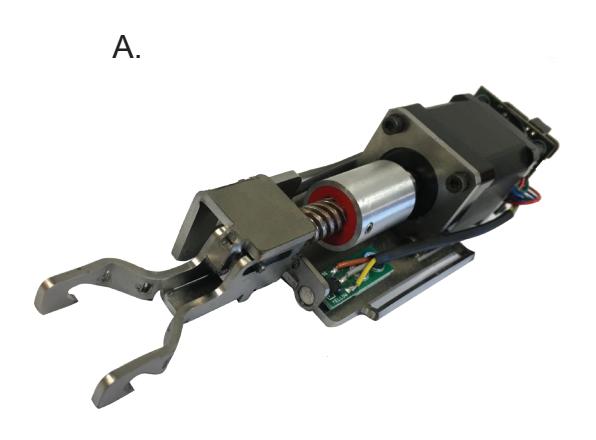
1- Motor Mount A.
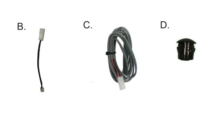
1- MM4S Socket Lead B.
1- 8' Lead w/ VD Connector C.
1- Dogging Hole Cap D.
Kit Includes Tools Required
Cordless Drill Hammer & Pin Punch(recommend) or 3/16 drill bit 5/16 Nut driver (recommended) or Flat head screwdriver #2 Phillips head screwdriver
TECHNICAL INFORMATION

SPECIFICATIONS
- INPUT VOLTAGE: 24VDC +/- 10%
- WIRE GAUGE: MINIMUM 18 GAUGE
- DIRECT WIRE RUN NO RELAYS OR ACCESS CONTROL UNITS IN-BETWEEN POWER SUPPLY & MODULE
STANDARD TORQUE MODE
AVERAGE LATCH RETRACTION CURRENT: 1 AMP AVERAGE HOLDING CURRENT: 215 MA
HIGH TORQUE MODE
AVERAGE LATCH RETRACTION CURRENT: 2 AMP AVERAGE HOLDING CURRENT: 250 MA
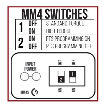
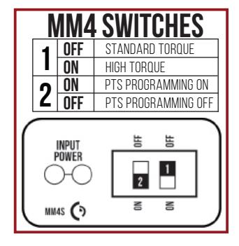
SETTING PTS

MAKE SURE TO SET PTS BEFORE FINISHING INSTALLATION
- STEP 1- SELECT YOUR PREFERRED TORQUE MODE (SHIPS IN STANDARD TORQUE) PRESS THE DEVICE PUSH PAD TO THE DESIRED SETTING. (RECOMMEND TO FULLY DEPRESS AND RELEASE 5%, GIVING THE DEVICE ROOM FOR CHANGING DOOR CONDITIONS.)
- STEP 2- WHILE DEPRESSING THE PUSH PAD, APPLY POWER. (I.E. PRESENTING THE CREDENTIAL TO THE READER).
- STEP 3- CONTINUE TO KEEP PAD DEPRESSED, THE DEVICE WILL BEEP 6 TIMES. AFTER THE BEEPS HAVE STOPPED, RELEASE THE PAD AND NOW THE ADJUSTMENT IS COMPLETE. IF NOT TO YOUR LIKING REPEAT THE 3 STEPS.
- STEP 4- ONCE YOU FOUND THE CORRECT LOCATION, TURN PTS SWITCH TO OFF POSITION.
TROUBLESHOOTING & DIAGNOSTICS
| BEEPS | EXPLANATION | SOLUTION |
|---|---|---|
| 2 Beeps | Over Voltage | > 30V unit will shut down. Check voltage & adjust to 24 V. |
| 3 Beeps | Under Voltage | < 20V unit will shut down. Check voltage & adjust to 24 V. |
| 4 Beeps | Failed Sensor | Verify all 3 sensor wires are installed correctly. Replace sensor if problem persists by contacting office. |
| 5 Beeps | Retraction or dogging failure | After 1st fail: 5 beeps then immediately attempts to retract again. After 2nd fail: 5 beeps with pause in-between for 30 seconds then device attempts to retract again. After 3rd fail: 5 beeps every 7 minutes, device will not attempt to retract. To Reset: Depress bar for 5 seconds at any time. |
| 6 Beeps | PUSH TO SET | Device is recording it's new position and power mode after the 6th beep. |
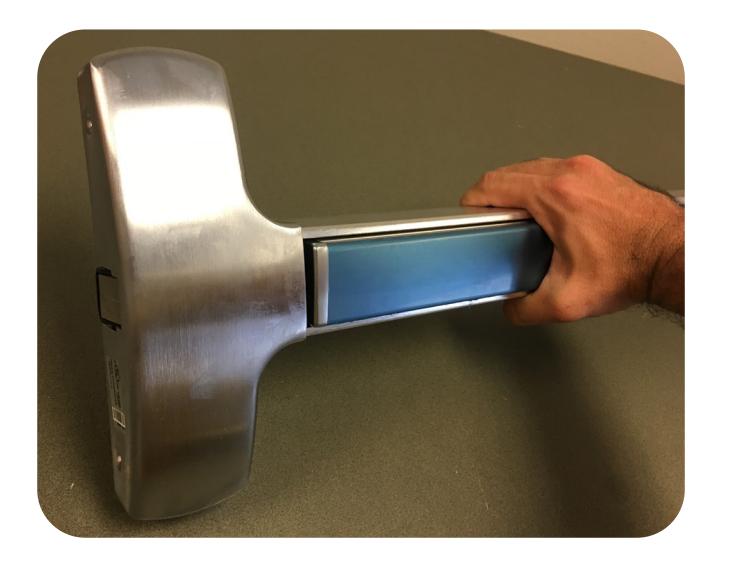
Electrified Exit Device
Installation Example

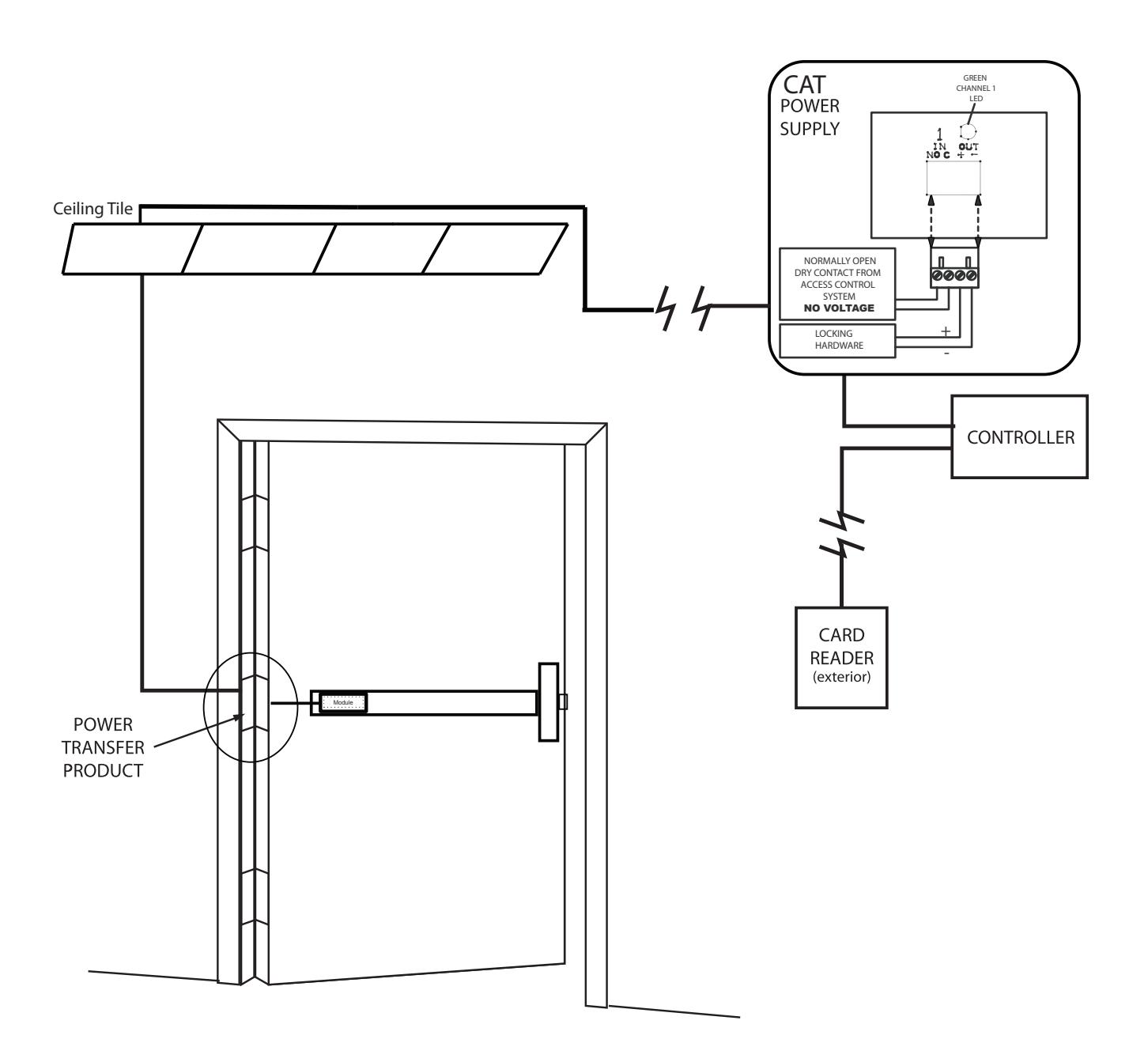
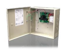
Recommended Power Supplies:
All Command Access exit devices & field installable kits have been thoroughly cycle tested with Command Access power supplies at our factory.
I n s ta l l at i o n I n s t r u c t i o n s

Remove (2) screws on mounting bracket with 5/16" nut driver. 1.
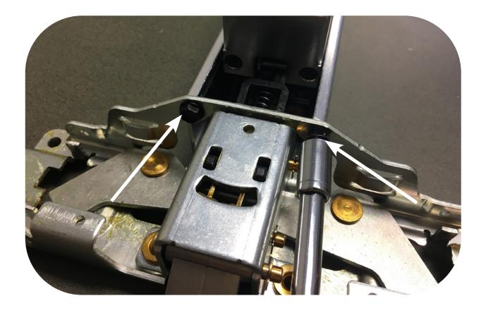
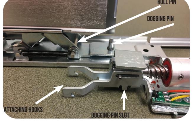
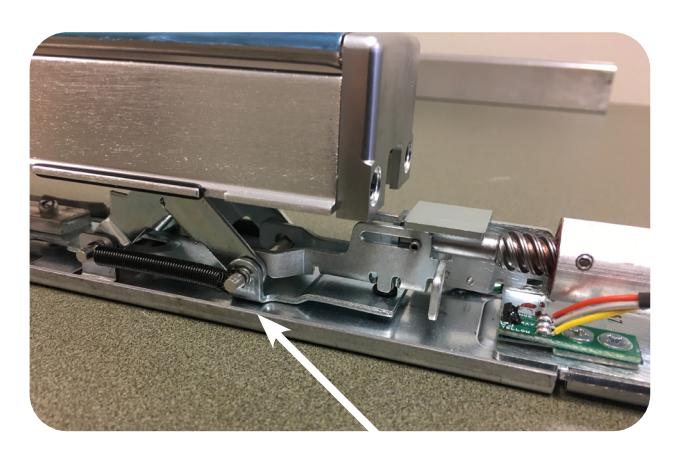
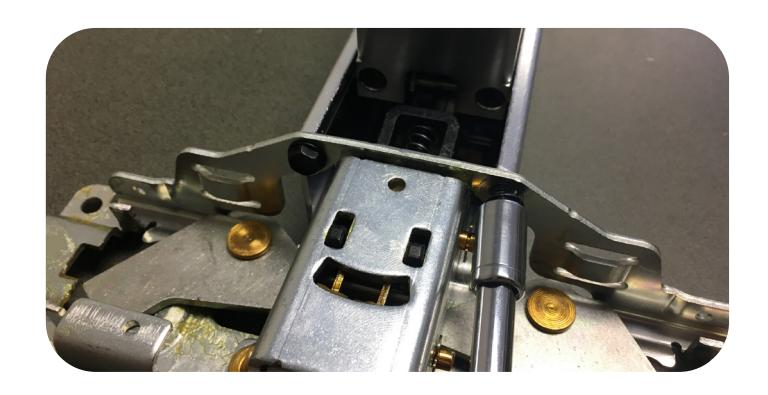
At the back of the baserail will be our installation with the kit grabbing onto the roll pin under the push pad 3.

Slightly depressing the push pad and keep the attaching hooks steady; grab onto the roll pin. 4.
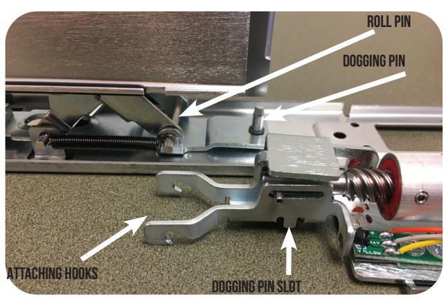
Make sure dogging pin lines up to slot on the underside of the kit as you grab onto the roll pin. 5.
Bring the back of the motor down onto the baserail. 6.
CONTINUED

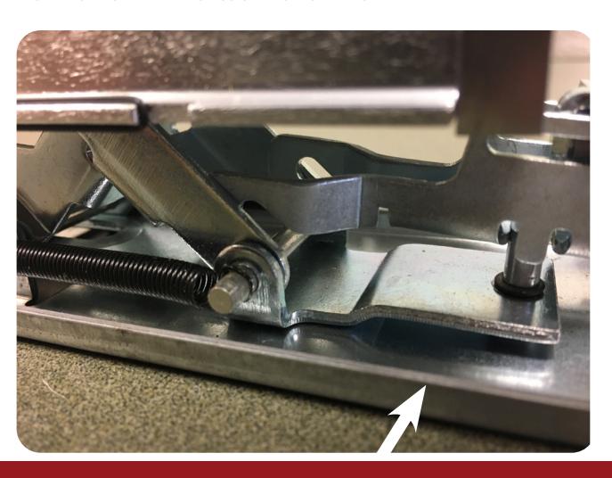
Line up slots in motor mount to drop onto exsisting tabs in baserail. 7.
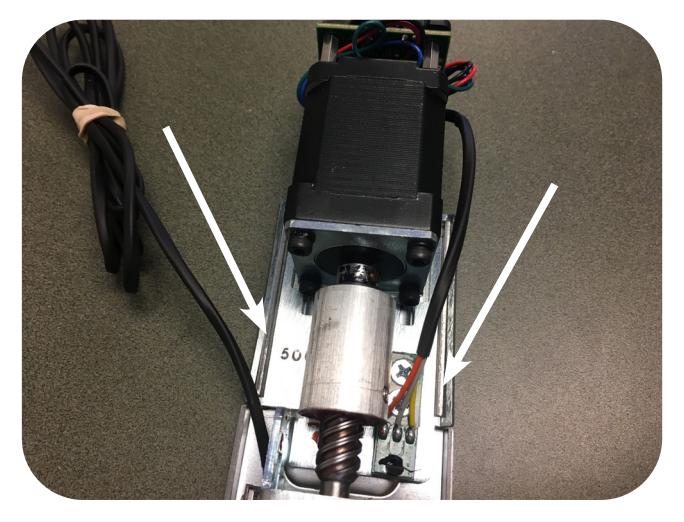
Visually confirm hooks are attached to roll pin. If not repeat Step B. 8.
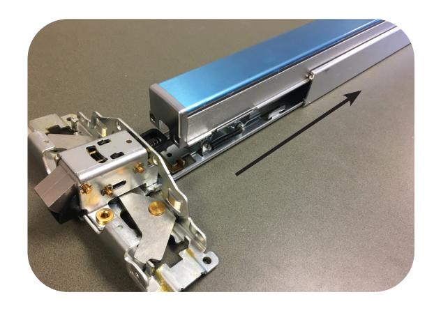
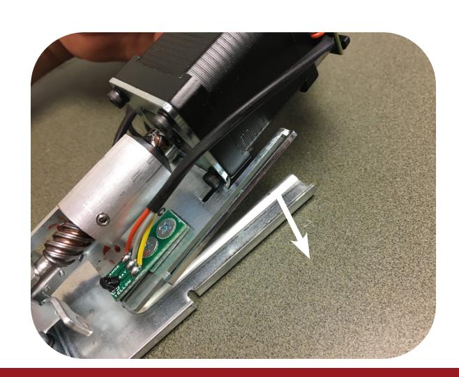
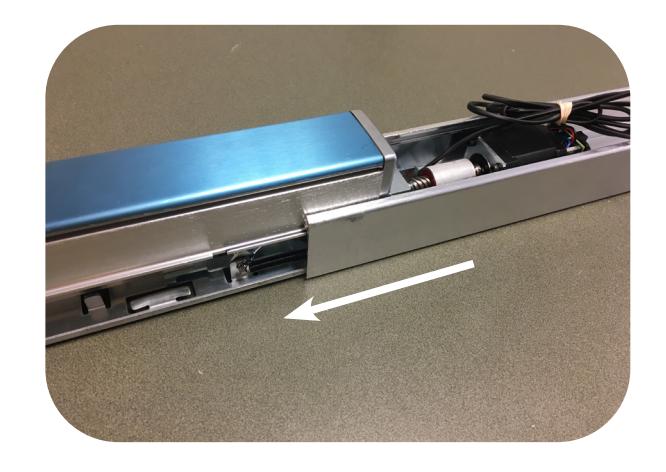
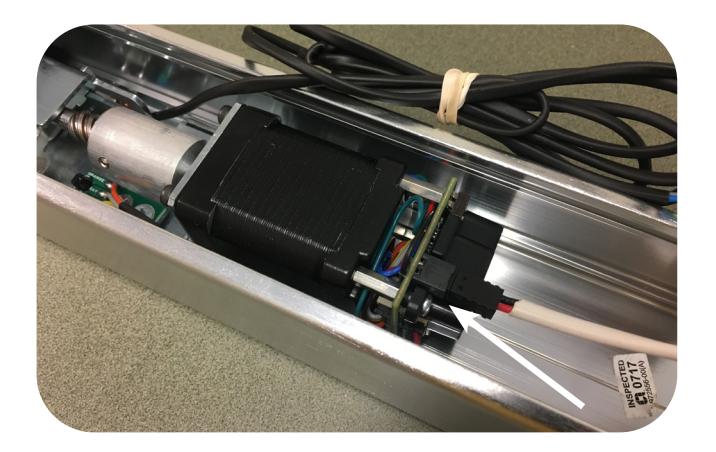
Slide the housing back onto the baserail making sure the motor & baserail are in the correct channel. Be cautions of pinching motor/REX wires. 9.
Re-install (2) screws on mounting bracket with 5/16" nut driver. 10.
CONTINUED

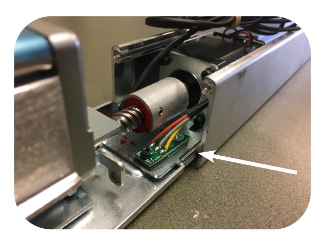
11. NEXT, PLUG IN THE MM4S SOCKET LEAD CONNECTOR INTO THE MM4S
12. SET USING THE PTS INSTRUCTIONS BELOW, REMEMBERING TO TURN THE PROGRAMMING SWITCH TO THE OFF POSITION WHEN COMPLETED.
Setting PTS
**Important Info** Make sure to set PTS before finishing installation
- Step 1- Select your preferred torque mode (ships in standard torque) Press the device push pad to the desired setting. (Recommend to fully depress and release 5%, giving the device room for changing door conditions.)
- Step 2- While depressing the push pad, apply power. (i.e. presenting the credential to the reader).
- Step 3- Continue to keep pad depressed, the device will beep 6 times. After the beeps have stopped, release the pad and now the adjustment is complete. If not to your liking repeat the 3 steps.
- Step 4- Once you found the correct location, turn PTS switch to OFF position.